Team-BHP > 4x4 & Off-Roading > 4x4 Vehicles
Register New Topics New Posts Top Thanked Team-BHP FAQ


Reply
  Search this Thread
93,234 views
Old 26th July 2010, 11:43   #121
Senior - BHPian
 
ex670c's Avatar
 
Join Date: Nov 2004
Location: Chennai
Posts: 2,470
Thanked: 1,937 Times
Dreams

Quote:
Originally Posted by SPIKE ARRESTOR View Post
Hi Arka,

The points you have highlighted regarding the shifting lever, breather vents and magnetic drain plugs can be agreed upon. I fail to understand how two parts obtained from the same moulds have different thickness and mechanical properties (provided the same materials are used). The reason being if you have to add material in a part you will have to remove material from its mould, this process is usually irreversible and any manufacturer will never resort to such practices.

Also what advantage do you gain by making the T/C PTO cover heavier?

Spike

PS- Can you tell me the differences between 4 speed KMT Transmissions used in NGCS and pre NGCS versions?
Hi Spike,

I argee with you on the Moulding part. Maybe the material is denser then

The Advantage of making the PTO Cover and T-Case Bottom Cover heavier, is lesser deflections in the gearbox(T-Case) under operation.

I have not seen a KMT90 from a NGCS MM550.

Regards,

Arka

Last edited by ex670c : 26th July 2010 at 11:47.
ex670c is offline  
Old 26th July 2010, 11:55   #122
Senior - BHPian
 
SPIKE ARRESTOR's Avatar
 
Join Date: Nov 2009
Location: Germany
Posts: 2,854
Thanked: 1,532 Times

Quote:
Originally Posted by ex670c View Post
Hi Spike,

I argee with you on the Moulding part. Maybe the material is denser then

Arka
Oh no not again. Refer my previous post, I've mentioned that the material in both the transmissions is the same. I have the Transmission from the NGCS army right in front of me, hope you will see a similar one soon.

Spike
SPIKE ARRESTOR is offline  
Old 26th July 2010, 12:10   #123
Senior - BHPian
 
ex670c's Avatar
 
Join Date: Nov 2004
Location: Chennai
Posts: 2,470
Thanked: 1,937 Times
Kmt90

Quote:
Originally Posted by SPIKE ARRESTOR View Post
Oh no not again. Refer my previous post, I've mentioned that the material in both the transmissions is the same. I have the Transmission from the NGCS army right in front of me, hope you will see a similar one soon.

Spike
Hi Spike,

I maybe wrong wrt to the Casting of the Gearbox & T-Case.

Could be a different Vendor for different applications.

What about the heavier PTO Cover & T-Case Bottom Cover?

If possible please compare the Army KMT90 vs Civilian NGCS KMT90 vs older KMT90s.

Regards,

Arka
ex670c is offline  
Old 26th July 2010, 12:22   #124
Senior - BHPian
 
SPIKE ARRESTOR's Avatar
 
Join Date: Nov 2009
Location: Germany
Posts: 2,854
Thanked: 1,532 Times

Quote:
Originally Posted by ex670c View Post
Hi Spike,

I maybe wrong wrt to the Casting of the Gearbox & T-Case.

Could be a different Vendor for different applications.

What about the heavier PTO Cover & T-Case Bottom Cover?

If possible please compare the Army KMT90 vs Civilian NGCS KMT90 vs older KMT90s.

Regards,

Arka
Arka,

Vendors can be different but they cannot bugger around with the specifications of the components. Regarding the T-case bottom cover I've to physically check a few vehicles before I pass my comments. I have the details of Army KMT90 (pre NGCS and NGCS), civilian NGCS KMT90 but I'm unable to locate the detail on older versions of this T/m, once I get that I will post a complete synopsis. I think its time to hit the R&D library.

Spike

PS- Do you have any details/parts nos. of the above mentioned models? That would make my job easier.
SPIKE ARRESTOR is offline  
Old 26th July 2010, 12:37   #125
Senior - BHPian
 
fazalaliadil's Avatar
 
Join Date: Oct 2008
Location: Hyderabad
Posts: 2,022
Thanked: 672 Times

Quote:
Originally Posted by ex670c View Post
If possible please compare the Army KMT90 vs Civilian NGCS KMT90 vs older KMT90s.
Arka/ Spike,
I believe the build quality of the army KMT-90 gearbox is better, it shows. If the production is from the same block why the differences mentioned by Spike? Could it be that the army gearboxes are outsourced to some other manufacturer?

Spike, the best option is to weigh the empty shells to ascertain if they are thicker or have higher density.
Regards,
fazalaliadil is offline  
Old 28th July 2010, 12:15   #126
Senior - BHPian
 
fazalaliadil's Avatar
 
Join Date: Oct 2008
Location: Hyderabad
Posts: 2,022
Thanked: 672 Times

Progress here.

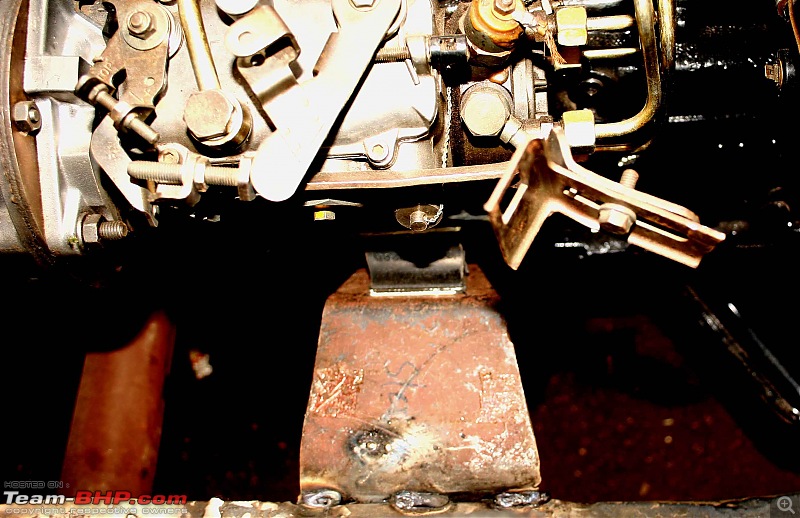
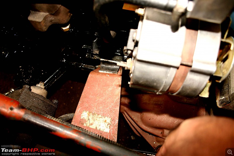
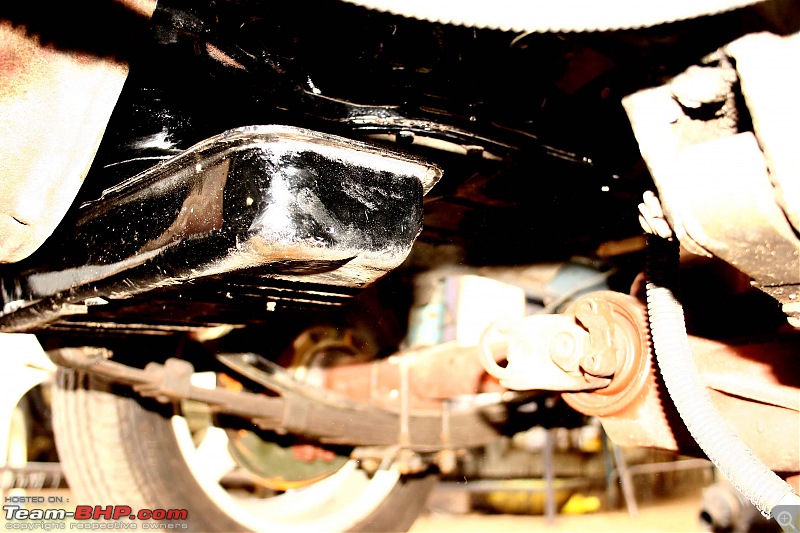
The engine is mounted on stock 540/550 foundation brackets which have not been fully welded, as the vibrations need to be checked before the full weld. Engine sits pretty good inside the bay but as JeepMkd had predicted the oil sump is in the way of the front propeller shaft, needs to be cut. The sump sits pretty high allowing a lot of GC as compared to other Peugeot engines. The reduction in oil capacity due to the shortening of the sump has to be compensated, don't want the engine to run on a loss of 1/2 liter.

The flooring has been cut to accommodate the KMT-90 gear box, now the need is to fabricate a new shield for it.

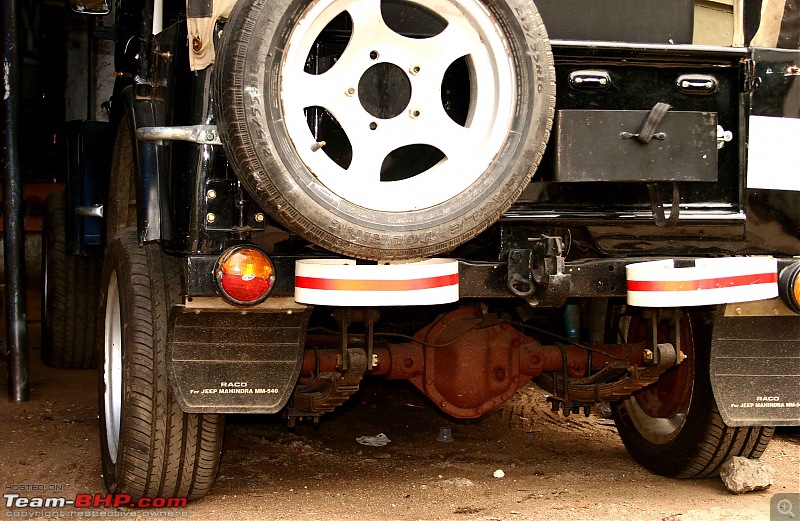
The wider track 550 diffs is telling after the front fenders have been fitted. which will have and advantage of better turning radius and on/ off road stability on a 3B, apart from disc brakes and LSD.

The hoses and fuel delivery pipes are being connected for a 5 minute run to check for vibrations, it may be in a couple of days. Will update as I move further.

The 15" wheels need to go urgently prior to the leaf spring job.

Regards,

Front track, before.
CJ3B, 'The Dog 2' or 'The Pup': Should I ??-img_6339.jpg
after.
CJ3B, 'The Dog 2' or 'The Pup': Should I ??-img_7356.jpg
Rear.
CJ3B, 'The Dog 2' or 'The Pup': Should I ??-img_7361.jpg
Left bracket.
CJ3B, 'The Dog 2' or 'The Pup': Should I ??-img_7346.jpg
Right bracket.
CJ3B, 'The Dog 2' or 'The Pup': Should I ??-img_7347.jpg
Wish it could be mounted on these original Ford brackets.
CJ3B, 'The Dog 2' or 'The Pup': Should I ??-img_7367.jpg

CJ3B, 'The Dog 2' or 'The Pup': Should I ??-img_7354.jpg

CJ3B, 'The Dog 2' or 'The Pup': Should I ??-img_7364.jpg
High position of oil sump, and also obstructing the path of the front shaft.
CJ3B, 'The Dog 2' or 'The Pup': Should I ??-img_7372.jpg

CJ3B, 'The Dog 2' or 'The Pup': Should I ??-img_7344.jpg

Last edited by fazalaliadil : 28th July 2010 at 12:18.
fazalaliadil is offline  
Old 28th July 2010, 13:03   #127
Senior - BHPian
 
ex670c's Avatar
 
Join Date: Nov 2004
Location: Chennai
Posts: 2,470
Thanked: 1,937 Times
Crank Case

Quote:
Originally Posted by fazalaliadil View Post
Progress here.

The engine is mounted on stock 540/550 foundation brackets which have not been fully welded, as the vibrations need to be checked before the full weld. Engine sits pretty good inside the bay but as JeepMkd had predicted the oil sump is in the way of the front propeller shaft, needs to be cut. The sump sits pretty high allowing a lot of GC as compared to other Peugeot engines. The reduction in oil capacity due to the shortening of the sump has to be compensated, don't want the engine to run on a loss of 1/2 liter.

The flooring has been cut to accommodate the KMT-90 gear box, now the need is to fabricate a new shield for it.

The wider track 550 diffs is telling after the front fenders have been fitted. which will have and advantage of better turning radius and on/ off road stability on a 3B, apart from disc brakes and LSD.

The hoses and fuel delivery pipes are being connected for a 5 minute run to check for vibrations, it may be in a couple of days. Will update as I move further.

The 15" wheels need to go urgently prior to the leaf spring job.

Regards,

Front track, before.
Attachment 395256
after.
Attachment 395257
Rear.
Attachment 395258
Left bracket.
Attachment 395259
Right bracket.
Attachment 395260
Wish it could be mounted on these original Ford brackets.
Attachment 395261

Attachment 395262

Attachment 395263
High position of oil sump, and also obstructing the path of the front shaft.
Attachment 395264

Attachment 395265

Hi Fazal,

Have you tried changing the Oil Pan/Sump/Crank Case with that of a XDP4.9 (2112cc)

Regards,

Arka
ex670c is offline  
Old 28th July 2010, 13:28   #128
Senior - BHPian
 
fazalaliadil's Avatar
 
Join Date: Oct 2008
Location: Hyderabad
Posts: 2,022
Thanked: 672 Times

Quote:
Originally Posted by ex670c View Post
Hi Fazal,
Have you tried changing the Oil Pan/Sump/Crank Case with that of a XDP4.9 (2112cc)
Hi Arka,

That's a brilliant idea!

I have attached a pic of the entire sump outlined in red. The up red arrow is the shallowest part and the down red arrow is the deepest, that is how far the sump extends. Does the XDP4.9 have the same kind of fit where the fasteners go on, in the under belly?

Should it fit, do you advise to change it or maintain this high perched sump for better GC as its high position will have an advantage and make it less vulnerable?

Also on my mind is to add the same cc on the shallow area, what I have to reduce on the deep area as not to lose oil capacity.

Regards,
CJ3B, 'The Dog 2' or 'The Pup': Should I ??-img_7372.jpg

Last edited by fazalaliadil : 28th July 2010 at 13:35.
fazalaliadil is offline  
Old 9th August 2010, 10:14   #129
Senior - BHPian
 
SPIKE ARRESTOR's Avatar
 
Join Date: Nov 2009
Location: Germany
Posts: 2,854
Thanked: 1,532 Times
Engine mounting integrity

Fazal Sir, from the pics I see that the Engine mounting brackets on the chassis are tack welded before final installation. Which are these? have they been fabricated for this application?

I am concerned about the power plant inclination and its mounting. If this is improper, the power-train will move back and forth when SPIKEd, please do not compromise on this.

Spike

PS- In case, you want to check this value of engine inclination you can do this easily with a bevel protractor, clinometer or a bubble gauge. If these brackets are hand made, I would insist on checking the engine inclination at this stage, this would give you peace of mind in the long run.
SPIKE ARRESTOR is offline  
Old 9th August 2010, 13:15   #130
Senior - BHPian
 
fazalaliadil's Avatar
 
Join Date: Oct 2008
Location: Hyderabad
Posts: 2,022
Thanked: 672 Times

Quote:
Originally Posted by SPIKE ARRESTOR View Post
Fazal Sir, from the pics I see that the Engine mounting brackets on the chassis are tack welded before final installation. Which are these? have they been fabricated for this application?

I am concerned about the power plant inclination and its mounting. If this is improper, the power-train will move back and forth when SPIKEd, please do not compromise on this.

Spike

PS- In case, you want to check this value of engine inclination you can do this easily with a bevel protractor, clinometer or a bubble gauge. If these brackets are hand made, I would insist on checking the engine inclination at this stage, this would give you peace of mind in the long run.
Spike,
Thank you for your concern.

These brackets are original what come on the 540 and have been purchased from a Mahindra dealer here.

Important point brought up by you is, the value of engine inclination. What should it be, can you please elaborate on that and should I use a bubble gauge what should be the level of inclination or should the engine be zero level (bubble bang in center) ?

Regards,

Last edited by fazalaliadil : 9th August 2010 at 13:18.
fazalaliadil is offline  
Old 9th August 2010, 13:16   #131
Senior - BHPian
 
headers's Avatar
 
Join Date: May 2006
Location: Greater Chennai
Posts: 4,667
Thanked: 559 Times

Quote:
Originally Posted by SPIKE ARRESTOR View Post

I am concerned about the power plant inclination and its mounting. If this is improper, the power-train will move back and forth when SPIKEd, please do not compromise on this.
A noob question spike.. if the spike arrestor is set properly then does it matter if the engine has a slight tilt?


There are some modern engines that are mounted at an angle - But fortunately there are FWD vehicles


OT:
Another question - Why does the XD3P oscillate from side to side when floored?

Last edited by headers : 9th August 2010 at 13:19.
headers is offline  
Old 9th August 2010, 14:54   #132
Senior - BHPian
 
SPIKE ARRESTOR's Avatar
 
Join Date: Nov 2009
Location: Germany
Posts: 2,854
Thanked: 1,532 Times
Engine inclination and vibrations

Quote:
Originally Posted by fazalaliadil View Post
Spike,
Thank you for your concern.

These brackets are original what come on the 540 and have been purchased from a Mahindra dealer here.

Important point brought up by you is, the value of engine inclination. What should it be, can you please elaborate on that and should I use a bubble gauge what should be the level of inclination or should the engine be zero level (bubble bang in center) ?

Regards,
IIRC, original Jeep specifications refer to a 6 1/2 degree inclination (North-South). The specifications for CJ3B and MM series are also the same, the maximum variation that I can think of is +- 10' (minutes). The bubble gauge should give the same readings when measured from both sides of the engine. This means the installation of engine mounting brackets is correct.

In a manufacturing set up a lot of jigs and fixtures are used which also take care of manufacturing tolerances. A slight deviation even in minutes could lead to catastrophic results on a large scale setup. Although, I don't have the faintest of doubts on the workmanship, but still I would insist you to get this checked, if possible. The feeling of doing a perfect job is priceless, and you know that very well :-).

Quote:
Originally Posted by headers View Post
A noob question spike.. if the spike arrestor is set properly then does it matter if the engine has a slight tilt?


There are some modern engines that are mounted at an angle - But fortunately there are FWD vehicles


OT:
Another question - Why does the XD3P oscillate from side to side when floored?
Vikram, engines may be kept at an inclination or otherwise, all depends on application and packaging factors. The spike arrestor will still work, but for it to work perfectly the engine inclination must be correct.

The answer to your question on engine oscillations with a XD3P attributes to a beautiful theory on Vibration Isolation and Transmissibility. Without getting into much details, I would try and explain this in a simple way. The engine/transmission etc are mounted on resilient rubber mounts. As the torque produced by an engine fluctuates (fluctuation path traced by a sine curve) these disturbances travel through the brackets through the resilient mounts, the mounts flex unflex giving the oscillations. Hence, it is the property of the damping material (Hard/soft) which determines how the system vibrates. Also the amount of shocks/disturbances which transmits through depends on the material properties of the dampener, this is called as Transmissibility. I am attaching a pic which shows how a system vibrates under various conditions (hard,medium,soft)

Spike

PS- Have you ever noticed special care being taken while installing the foundation members for heavy machine beds? ^^ is the exact reason for doing this.
Attached Thumbnails
CJ3B, 'The Dog 2' or 'The Pup': Should I ??-damping.jpg  

SPIKE ARRESTOR is offline  
Old 9th August 2010, 15:52   #133
Senior - BHPian
 
fazalaliadil's Avatar
 
Join Date: Oct 2008
Location: Hyderabad
Posts: 2,022
Thanked: 672 Times

Thanks Spike,

The basic way the engine mounts were done:

1 Fitted the Gearbox on the cross member with new foundations and fully secured it.

2 The engine was made to align with the gearbox bell housing and fastened, meanwhile the engine was supported with jacks.

3 After the alignment was considered best, the engine mounting brackets were placed and temporarily welded at that position.

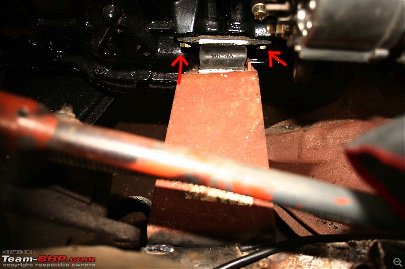
As this too is a Peugeot engine, the original mounts (Ford) holes on the engine side and the holes of the (bought) 540 mounts are the same (red arrow).

How accurate is the above 1-3 method and to what degree could be the margin of error?

Does the compression of foundation rubbers (in pic.) tell any story?

Thanks,
CJ3B, 'The Dog 2' or 'The Pup': Should I ??-img_7346.jpg

CJ3B, 'The Dog 2' or 'The Pup': Should I ??-img_7348.jpg

Last edited by fazalaliadil : 9th August 2010 at 15:58.
fazalaliadil is offline  
Old 9th August 2010, 16:08   #134
Senior - BHPian
 
SPIKE ARRESTOR's Avatar
 
Join Date: Nov 2009
Location: Germany
Posts: 2,854
Thanked: 1,532 Times

Quote:
Originally Posted by fazalaliadil View Post
Thanks Spike,

The basic way the engine mounts were done:

1 Fitted the Gearbox on the cross member with new foundations and fully secured it.

2 The engine was made to align with the gearbox bell housing and fastened, meanwhile the engine was supported with jacks.

3 After the alignment was considered best, the engine mounting brackets were placed and temporarily welded at that position.

As this too is a Peugeot engine, the original mounts (Ford) holes on the engine side and the holes of the (bought) 540 mounts are the same (red arrow).

How accurate is the above 1-3 method and to what degree could be the margin of error?

Does the compression of foundation rubbers (in pic.) tell any story?

Thanks,
Sir, the procedure followed by you (1-3) is correct, however among these step 3 is the most critical. Was the engine resting on its own weight (while still being supported by jacks) before the tack welding was done? If yes, then I don't see any issue. The reason why I am asking this is:- when engine rests on the mounts the mounts deform slightly and finally settle down in an equilibrium position. It is in this position the welding must be done. A proper execution of all the 3 steps leave very little margin for error.

Spike

PS- I can see a slight bulge in the insulator (2nd pic), I may be mistaken.

Last edited by SPIKE ARRESTOR : 9th August 2010 at 16:10. Reason: add info
SPIKE ARRESTOR is offline  
Old 10th August 2010, 01:38   #135
BHPian
 
JeepMkd's Avatar
 
Join Date: Feb 2009
Location: Republic of MACEDONIA
Posts: 86
Thanked: 3 Times

I was on a vacation so now I see how much I've missed. It's great to see that you are making progress.
JeepMkd is offline  
Reply

Most Viewed


Copyright ©2000 - 2024, Team-BHP.com
Proudly powered by E2E Networks