| |||||||

| Search Forums |
| Advanced Search |
| Go to Page... |
 |
| Search this Thread |  40,696 views |
 12th July 2020, 21:30
| #1 |
| Distinguished - BHPian  | DIY - ICE ICE Baby! Audio System Revamp in my Alto K10 My 2nd car is the weird looking pocket rocket - Alto K10 - acquired it near the end of 2017 IIRC. Its a VXi (O) AGS (i.e. AMT). Technically the car is my wife's. Bought for her, by her. As her office ride but on my car make recommendation. Her 1st preference was Nano XTA. 2nd Preference was Tiago XZA. A Maruti was never really an option. Doing the math of the potential running (or none at all) that I had anticipated in my mind I suggested saving money and opting for the Alto K10 instead as a golden midway between the Nano & the Tiago. (for once, I wasn't proven wrong in that math!) An year or so after the acquisition, things took multiple turns for both of us and eventually she didn't have much of a need to drive the car. (With Covid19 around - this will change & if the offices open up again, she'll be going to office by the car of course). We also use the car for errands within the city confines, school runs. Once in a while I drove it to office just to ensure it got sufficient running! Since I became responsible for the car & her upkeep, slowly but surely I started work on it to bring some good features into it. First of course was illumination upgrade with implementation of HID Bi-Xenon projector fog lights. The details for it are already documented here - Link - Alto K10 HID Fog-light DIY thread. (DIY - Maruti Alto K10 - HID Fog Light Installation) Next is this project. A complete revamp of the In Car Entertainment - ICE - in the car from the stock setup - a Nippon CD player (with USB but without Bluetooth) and 2 front speakers. Do note that the intention is to bring a better utility from the head unit and some good quality sound output compared to the stock setup. I was/am not looking at all for a pro setup that turns the car into a dance floor. So I have relied mostly on cost effective (cheap!) stuff that just about gets the job done in a daily rider. Nothing more. Here is an index of steps for quick referencing -
(Yeah, finally mastered the art of making an in-thread index! Courtesy of @Aditya's thread here - Making Index in Thread. (How to add an 'index' to your thread)) This is how the car's dashboard is by default. (Lazy I am - siphoning a pic off the TBHP Official review!)  The car came with an age old CD player with 2 cheap speakers in the front door pads. Nice to see a CD player once in a while, but fact is - nobody uses them anymore. It has no Bluetooth for telephony either. We never thought of upgrading this system as such. But then came the Nexon to share the parking with the Alto. The music in that car really started to make the Alto disliked! Needed an ICE upgrade. At least a couple of ovals in the rear parcel tray. So lazily I did check the Pioneers on amazon.in but never really felt like going through all the hassle. Around end of June 2020 I got a message from my friendly contact Rishi from whom I have acquired a lot of material (especially projector fog lights for my cars as well as for my friends). He was giving a whopper discount on Android touch screen systems for 2 days. An Alto K10 compatible unit (with OEM spec face plate included) would cost me ~8000 including a night-vision reversing camera he said. He had just lifted a big consignment of 1500 units of various car head units & was passing on some of the discounts. I had checked this system for a few months. It used to retail around 12000 for 1 GB and 14000 for 2GB RAM (More on that later in the thread. Do read!) & I didn't think about investing that much. But at 8000 INR - this was the push I needed to start this project. Ordered it from www.MotorBasket.com as usual and completed the payment with UPI in 10 seconds. I'm sure there would be some anxiety among car accessory dealers regarding goods originating from the PRC. Covid19 related business hit + the pathetic overture by the Chinese up in Ladhakh have created a high anti China atmosphere & there were calls for boycott of Chinese made goods when I ordered it & when I'm writing this thread. (I don't know how this boycott is possible in short term of course but that's best discussed on the political threads). So - I'm sure I got this discount resulting from some sort of urgent Chinese stock clearance happening somewhere. I have a small guilt in mind of buying a Chinese made unit when there are/were tensions on the border unlike any since decades with the Reds. General Specifications & features of the system -
Kit contents -
 Head Unit Product listing - Link : MotorBasket.com Alto K10 Android Head Unit (Of course in this ever changing world, I don't know how long the listing will stay. But you can look up on Amazon and there is a crop of similar systems everywhere now.) Ordered the 2 Oval Pioneer speakers to install in the rear tray. Ordered the necessary speaker wires with RCA connectors and a couple of RCA splitters (in case I need them somewhere during the project) & started the wait. Didn't go overboard with too much high-quality and costly stuff. I wasn't looking for anything jazzy in this little hatch. List of items purchased - Here is the list of items that I ordered in case anyone needs them -
Instead of the RCA Splitter & a stereo RCA cable, you can opt for a single product - 1:2 split RCA cable. This will reduce 1 extra connection that can potentially induce some noise over time.
Now scroll up & see the last item in the head unit's features. An amplifier pre-out. Yey!  The moment I saw this in the rear of the system - I was reminded of the JBL amplifier & sub-woofer box lying in storage with me. The set that I had removed from my Vista before sending her off. Had planned on installing it in the Nexon - but simply didn't have the need given the potent stock setup of the Nexon & very usable large boot! The moment I saw this in the rear of the system - I was reminded of the JBL amplifier & sub-woofer box lying in storage with me. The set that I had removed from my Vista before sending her off. Had planned on installing it in the Nexon - but simply didn't have the need given the potent stock setup of the Nexon & very usable large boot!Items used from my existing inventory -
Last edited by Reinhard : 23rd July 2020 at 23:47. |

|  (28)
Thanks (28)
Thanks
 |
| The following 28 BHPians Thank Reinhard for this useful post: | aah78, AdityaDeane, Aish_4761, akshye, ast.ggn, badboyscad, chiranjitp, dailydriver, digitalnirvana, fiat_tarun, gmhossain, Grease_Monkey, GTO, GutsyGibbon, harry10, InControl, Keeleri_Achu, Myth_sx, R2D2, Rambo-RS, samaspire, skyocean, smuniswami, The_Outsider!, vaasu, vvvinod, wheelguy, zaphodb |
| |
|
12th July 2020, 22:09
| #2 |
| Distinguished - BHPian | re: DIY - ICE ICE Baby! Audio System Revamp in my Alto K10 Understanding the Android HU Wiring Wire connection mock-up - I have connected all the leads of the wires where they should be connected & named each of them. This should simplify understanding what goes where. All the connectors are smartly coordinated with unique couplers with orientation guide notches so you simply cannot get any of them wrong. The connectors fit only their intended socket & nothing else. So no thinking needed.  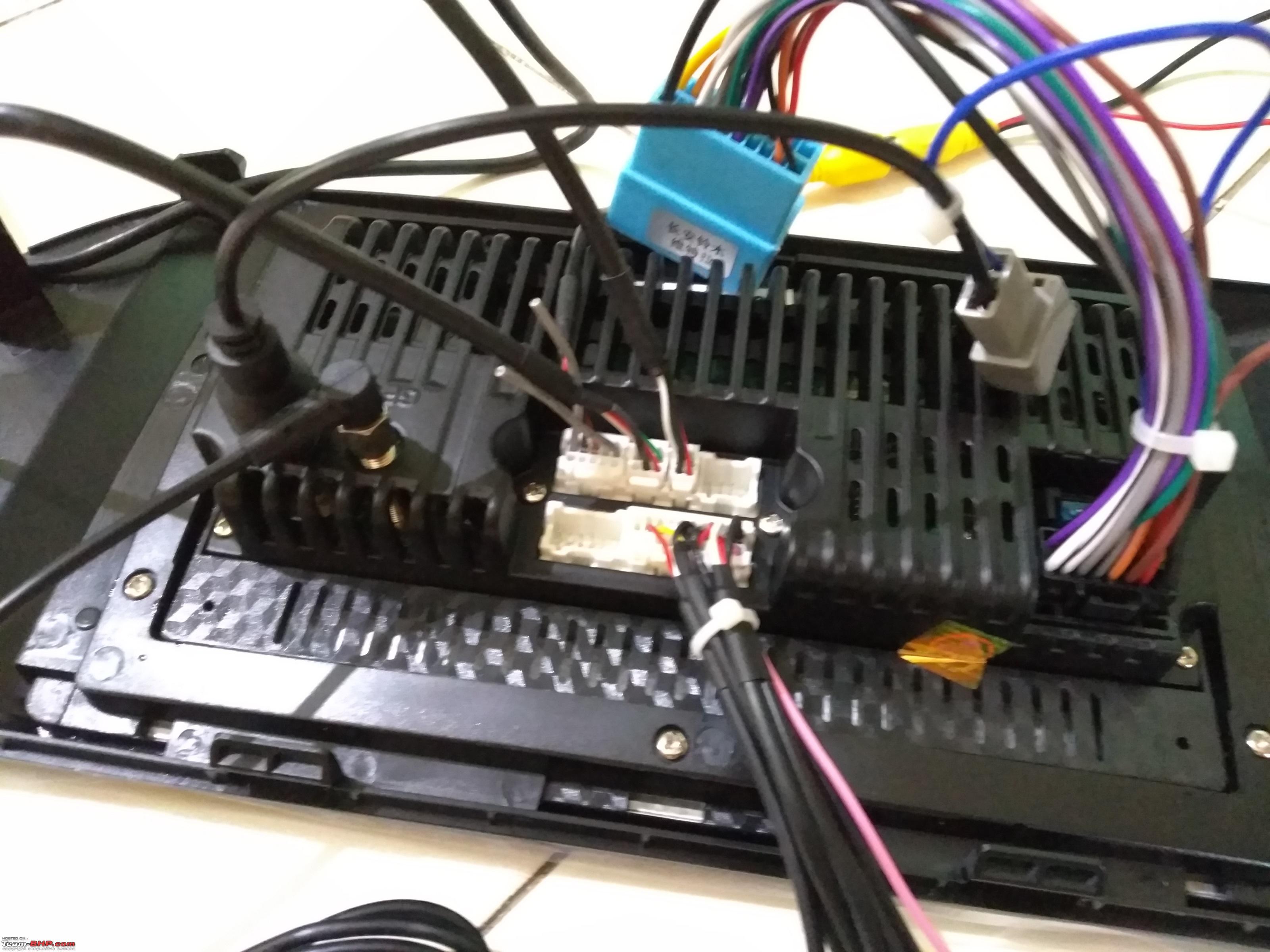 Camera & Amplifier signal connections - If you are not going to install any reverse camera (or the wiring for that is already in place in your car) and / or amplifier + sub-woofer - as soon as you understand the wiring as in the image above - you are good to go in the parking & install the system. It is a plug & play setup & you hardly need to do anything at all. Just take out your old system if you have one, make these wire connections and couple it with the OEM harness present in the car with the provided OEM coupler. Fit the head unit into place & you are done! The only 2 things that need manually arranged connections are -
Amplifier Signal - Pink is the wire that sends signal to the amplifier when the head unit is ON. This means it works as a remote switch so that the amplifier activates only when the head unit is ON & doesn't use battery power when head unit is off. Reverse Signal - Brown wire is the 12V input signal, that tells the head unit when reverse gear is engaged. The way to do this is painfully simple.
In the image below, you can see that I have used the humble wire connector for doing these connections. I simply cannot stand insulation tape over twisted wires! when a proper molded connector is not possible - I resort to these cheap wire connector strips. To ensure the screws do not loosen up with vibrations, I fill up the connectors with silicone as the last step of installation when everything is tested. You can also see that I have also left 1 extra connection terminal available. In case I need to make any more connection for something at the back of the head unit (even unrelated to the HU for that matter.) (I'm sorry - I did an incorrect zoom while editing the images & the inset text comments that I have added appear too small in these thumbnails. Please click on the image and open it in full size to be able to read the tips and notes that I have written in them (mostly red font.)).  In the image below, the red wire in this small connection, goes to the +ve terminal wire of the reverse bulb on the RHS. Black to ground. The connector pin - goes to the camera as the power input. Turns on when reverse light turns on. The T Tap will be connected to the insulated connector crimped in the image above.  Additionally, we have to add a pair of scotch tap OR T-Tap connectors to both the black & red naked ends of the wire. I had T-Taps in inventory so went with them. These would tap into the stock wiring for the reverse light in the RHS tail lamp. That is covered in detail in the post below for installing the reverse camera. Last edited by Reinhard : 17th July 2020 at 19:54. |
|
| (16)
Thanks
|
| The following 16 BHPians Thank Reinhard for this useful post: | 2himanshu, aah78, AdityaDeane, ast.ggn, chiranjitp, dailydriver, digitalnirvana, GTO, InControl, Myth_sx, Prakritij, rakesh_r, smuniswami, The_Outsider!, vaasu, wheelguy |
|
13th July 2020, 10:24
| #3 |
| Distinguished - BHPian | re: DIY - ICE ICE Baby! Audio System Revamp in my Alto K10 Mounting Oval Speakers in Parcel Tray As mentioned earlier - the Alto K10 doesn't have any speakers in the back. Nor any provision in the door panels to mount a pair later. So - the only (and better) option left was to mount moderately good oval speakers in the rear parcel tray. I ordered Pioneer speakers off Amazon.
Didn't even think once about them being "duplicate" items or about checking the authenticity etc. The car has nothing right now. So anything is going to be better & I don't want to create a dance floor in the car as such.  Fitting the speakers - To my surprise - the PU plastic panel that forms the parcel tray is very tough. I didn't expect such a thick & sturdy item from MSIL in an Alto K10. I'm not joking when I say this - the panel is far stronger than any external metallic body panel. All the external sheets easily deform without any resistance just with a thumb. This parcel tray is STRONG.
The wiring - we'll do together with rest of the items. So at a later dedicated step for the wiring. Last edited by Reinhard : 20th July 2020 at 13:59. |
|
| (13)
Thanks
|


| The following 13 BHPians Thank Reinhard for this useful post: | aah78, AdityaDeane, ast.ggn, chiranjitp, dailydriver, digitalnirvana, GTO, InControl, Myth_sx, R2D2, SmartCat, smuniswami, The_Outsider! |
|
13th July 2020, 15:14
| #4 |
| Distinguished - BHPian | re: DIY - ICE ICE Baby! Audio System Revamp in my Alto K10 Removing the Stock Head Unit This is a pretty simple step & won't need much explanation or expertise at all. I'll let the pictures do the main talking. The only 3 things to do in this step -
Well - let's get on with it then!
Well that's it. This step is over in no time. It took me far longer to write about it than to actually carry it out. Last edited by Reinhard : 21st July 2020 at 14:56. |
|
| (15)
Thanks
|


| The following 15 BHPians Thank Reinhard for this useful post: | aah78, AdityaDeane, AZT, chiranjitp, dailydriver, digitalnirvana, GTO, InControl, Myth_sx, Prakritij, R2D2, SmartCat, smuniswami, The_Outsider!, vaasu |
|
13th July 2020, 15:16
| #5 |
| Distinguished - BHPian | re: DIY - ICE ICE Baby! Audio System Revamp in my Alto K10 Installing the Android Head Unit & its Wiring The head unit installation itself is actually very simple! If you are doing this in a car that already had all speakers etc in place - this step shouldn't take more than 30 minutes. Its that easy. Just attach the provided coupler with the one existing your car, fit the new head unit & face plate in place & you are done! We'll run the wires in 2 groups. 1 set along the LHS, another set along the RHS of the car.
So separate these out on both the sides before we start the wiring & ensure they aren't entangled or twisted. Keep it clean as it gets! Before we start the actual wiring - do these 3 steps for easy access under the dashboard -
RHS Wiring Detail
LHS Wiring Detail The steps are more or less identical on this side as well, just the wires are different. So I'll let the pictures explain most of the things.
Last edited by Reinhard : 23rd July 2020 at 22:56. |
|
| (19)
Thanks
|


| The following 19 BHPians Thank Reinhard for this useful post: | aah78, AdityaDeane, ast.ggn, chiranjitp, dailydriver, digitalnirvana, fiat_tarun, giri1.8, GTO, InControl, Myth_sx, nairrk, Prakritij, R2D2, rakesh_r, Sahilrai166, smuniswami, The_Outsider!, yogiii |
|
13th July 2020, 15:17
| #6 |
| Distinguished - BHPian | re: DIY - ICE ICE Baby! Audio System Revamp in my Alto K10 Wiring the Amplifier & Sub-Woofer The generally followed approach with amplifiers tends to be keeping the amp below the front passenger seat. I generally don't find it best considering it doesn't give proper ventilation to the amp. The floor mats tend to go over the amp. And also - the wiring & amplifier keep getting trampled under the rear passengers' feet! In an Alto K10, already space is nonexistent for the rear passenger. Depriving them of even a few square inches to rest feet would be a crime against humanity. So right from outset, I decided that the amplifier will sit together with the sub-woofer back in the boot. That would mean a few more feet of power wire from the battery to the amplifier, but the installation would be cleaner & far easier to maintain also. On Demand Bass! - Turn it off when not needed. Occasionally in the Vista some passengers used to feel the woofer output was too much for them. So this time, I'll have a switch to turn-off the amplifier. First I thought of installing the switch in the dashboard. However - that would fill up the single remaining dummy switch position. The number of times I'd actually need to switch off the amplifier would be fairly low. So I decided to use an illuminated press button switch at the back, stuck on the amplifier itself. When I need to switch off the amp - it would take only a minute to open the boot & turn it off. I can use the blank dummy position in the dashboard for something else in the future if I add it. The Amplifier -
 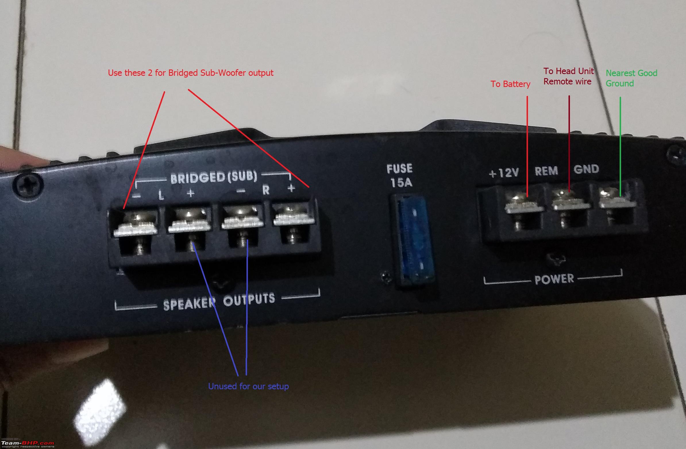 Amplifier Wiring Detail -
Modular Connection Tips -
The On Demand Amplifier Demo - Audio Input to Amplifier -
Installation Finished -   Wires neatly secured, tucked into the carpets. On RHS of the image is the back of the rear seat. LHS of the image is where the hatch opening is. Picture taken from RHS rear passenger door, seat slightly folded forward.  Last edited by Reinhard : 23rd July 2020 at 22:55. |
|
| (15)
Thanks
|


| The following 15 BHPians Thank Reinhard for this useful post: | aah78, AdityaDeane, ast.ggn, chiranjitp, dailydriver, digitalnirvana, GTO, Myth_sx, Prakritij, R2D2, samaspire, smuniswami, The_Outsider!, vaasu, Vmv |
|
13th July 2020, 15:19
| #7 |
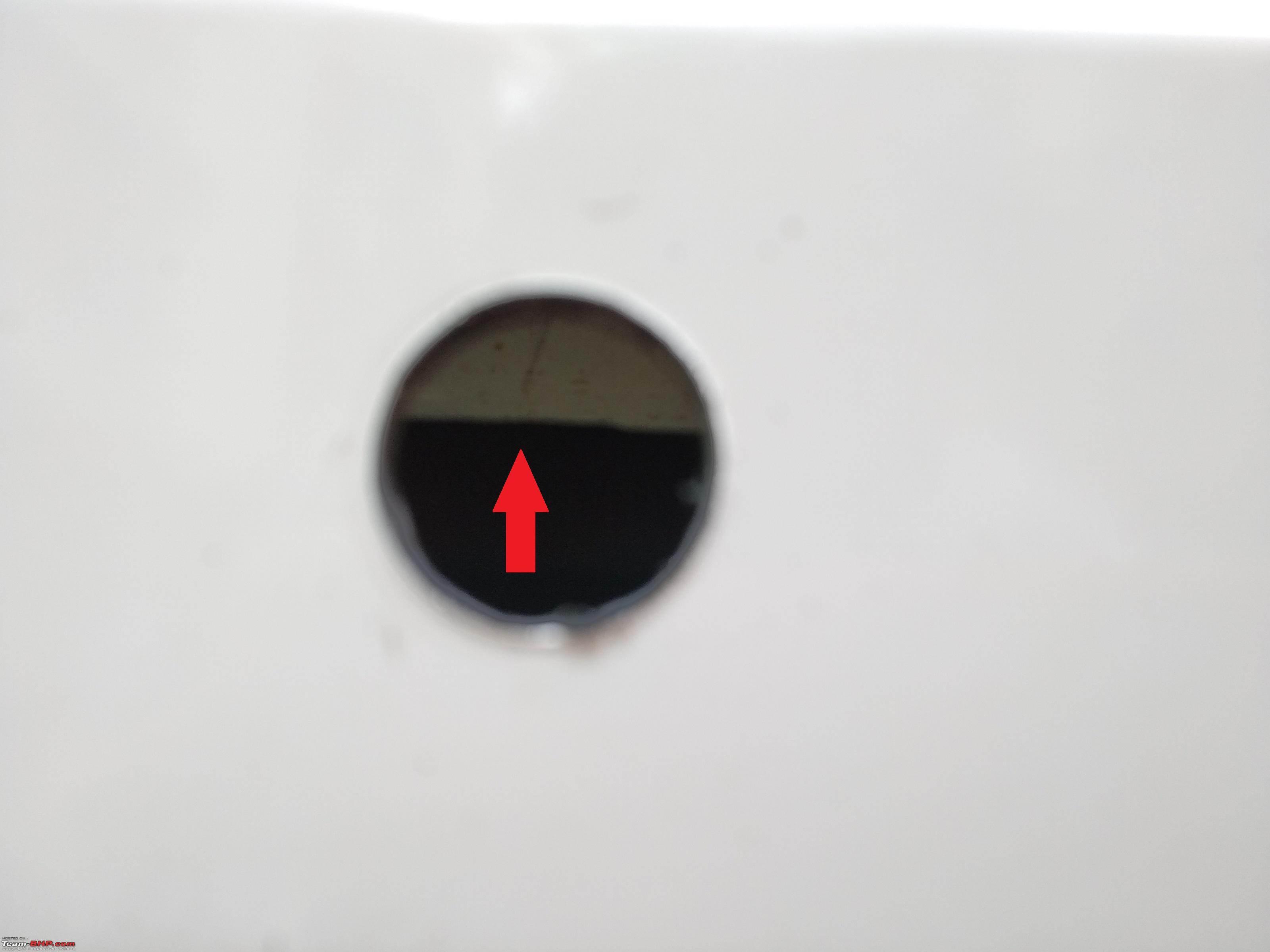
| Distinguished - BHPian | re: DIY - ICE ICE Baby! Audio System Revamp in my Alto K10 Installing the Reversing View Camera The camera sits in the rear bumper, midway and at a suitable height above the number plate. Fairly common positioning & no rocket science involved in zeroing in on the installation spot. As seen in the kit contents picture at top, the correctly sized drill bit to make the precise hole in the bumper is included along with the camera. This is a very good thing indeed, especially for DIY enthusiasts as now there is no need to find the exact size drill bit additionally. The Chinese sure do a good job of making packages self-sufficient since last few years. Originally I thought & planned on removing the rear bumper to complete the wiring & installation of the reversing camera. The moment I removed the tail lamp cluster on RHS - it was evident that bumper removal was not needed at all. Things were all fairly accessible! (The bumper by the way is held in place by just 3 bolts on top covered by the hatch, 2 press-fit-button type clips on the lower edge near mud-flaps & a couple of latch-clips on the sides around the wheel well. I was expecting at least a couple of more bolts.) So here's the step by step guide -
Last edited by Reinhard : 18th July 2020 at 19:28. |
|
| (19)
Thanks
|


| The following 19 BHPians Thank Reinhard for this useful post: | aah78, chiranjitp, dailydriver, digitalnirvana, fiat_tarun, Grease_Monkey, GTO, InControl, johy, lemedico, Myth_sx, navin, Prakritij, samaspire, smuniswami, The_Outsider!, TorqueIndia, vaasu, Vmv |
|
13th July 2020, 15:21
| #8 |
| Distinguished - BHPian | re: DIY - ICE ICE Baby! Audio System Revamp in my Alto K10 Testing & Closure Comments Initial Impressions - To say the least - I was blown away by how it turned out. For the price I paid (~8000 INR) I didn't expect the result I got.
I think I said it before but I'll reiterate. A 10" tablet without 4G SIM slot and around 2GB ram - costs about INR 10-12000 or so. This system packs the same punch as that one, has GPS navigation, pretty powerful amplifier, works in a car & fits flush. Provides cool entertainment while driving! For 8000 with a 1 year warranty & rear view camera I got a steal deal beyond any doubt. (Of course that was a limited period sale price & wasn't available 4 days later when I checked for a friend.) Here are the first images after power-up - (Do note - I had just rested the unit on its edge & not fixed it properly in place for this test. Hence it looks a bit protruding outwards. Better images below. After the test, I removed it and put it back in the box, now waiting for the connectors and wires for other equipment.)    Look closely & you'll see that the MCU version starts with "CVD"! What an unfortunate coincidence that it has all the consonants from "COVID". 2020 really is a wicked year. Also note - the head unit is pretty slim since it has no optical drive in it. It doesn't have a bracket to reach & mount on the 4 stock screw-holes in the dashboard like the stock head unit. Instead - this android system is mounted with screws into the face-plate. And the weight rests on the surrounding edges of the face-plate & the clips into the dashboard. Its light weight so won't be an issue, but be mindful to ensure that all clips fit properly & don't pop out while driving. Here are a couple of snaps after the installation was completed & I pushed the head unit into place. It was already getting dark & my mobile camera does a poor job in such lighting conditions I'm afraid.   Reverse Camera Test at Dusk - Here is a quick test of the reverse camera at quite late in the evening when it was starting to get pretty dark. As you can see, my camera is not able to properly cope up with the exposure due to the lack of ambient lighting. The camera output is more than satisfactory for the use even in full darkness. The RAM Conundrum! 2GB or 1GB? Or are they all 1GB with just a software hack? Naughty Chinese? So like I mentioned in the opening post, going back to the RAM scenario. Originally I had planned on buying a 2GB RAM system assuming more fluid response & faster behaviour by the OS. Rishi from MotorBasket kept me assured that even if I went with a 1GB system, I'd not notice any relative lag. So went with a 1GB system. I checked the RAM chip number from the ventilation gaps in the rear housing of the HU. Found 2 chips from SEC with IC number K4B2G0446D. These are DDR chips of 512MB each. 2 chips = 1GB RAM. I checked with Rishi & honestly he confirmed that it seems the units that he got from his supplier in China seem to have same 2 chips even in the 2GB options. Now unless the PCB in the 2GB system has another 2 chips on the underside - those are also with 1GB RAM & just have a software that shows 2GB. Smartly played Chinese folks!!  But then, there are some of us who take the pain to verify & know how electronic items are made! Take that China & dealers in India who might be aware of this! But then, there are some of us who take the pain to verify & know how electronic items are made! Take that China & dealers in India who might be aware of this!Rishi immediately removed all the 2GB listings from their portal after finding this. Afterwards - the Chinese dealer apparently accepted that a wrong batch was sent. The most recent consignment apparently has started seeing proper 2GB RAM chips on the units. I suggest buyers if opting for 2GB systems - better confirm the authenticity. (There is always a possibility like I mentioned - with 2 additional chips on the flip side of the PCB. But I don't know about it since I don't have a 2GB system & don't want to open and break the warranty seal. Considering how these things are generally structured, the chances of another set of chips are low. For a 2GB system, generally the approach is to install 2 chips of 1GB each instead of 512GB each so that the assembly line needs no extra step of flipping the PCB during soldering. Just load the banks with different chips & you get a 2GB system on same assembly line.) So that's another DIY complete. At a leisurely pace this time around as some of the items I ordered took eternity to deliver from Amazon thanks to random lockdowns all around the nation due to Covid19. I hope folks find it useful. Happy to help as always should one have a query! Last edited by Reinhard : 23rd July 2020 at 22:53. |
|
| (47)
Thanks
|
| The following 47 BHPians Thank Reinhard for this useful post: | 2himanshu, aah78, Artyom, ashking101, ast.ggn, AZT, CEF_Beasts, chiranjitp, dailydriver, Deepsp, digitalnirvana, Ertigiat, Geo_Ipe, gjnnbagal, Grease_Monkey, GTO, GutsyGibbon, harditthind, harry10, InControl, janakiram_m, keroo1099, K_Drive, lemedico, Myth_sx, nairrk, navin, Parts007, Prakritij, PraNeel, R2D2, Sahilrai166, samaspire, shancz, Shrayus_shirali, SmartCat, smuniswami, Tgo, The Great, The_Outsider!, Torq, TorqueIndia, vaasu, vhharan1, Vinod_nair, Vmv, windrider |
|
24th July 2020, 02:57
| #9 |
| Team-BHP Support  | re: DIY - ICE ICE Baby! Audio System Revamp in my Alto K10 Note from Support: Thread moved from the Assembly Line to the DIY section. Thanks for sharing! |

| (3)
Thanks
|
| The following 3 BHPians Thank aah78 for this useful post: | digitalnirvana, GTO, Reinhard |
|
24th July 2020, 03:01
| #10 |
| Team-BHP Support | re: DIY - ICE ICE Baby! Audio System Revamp in my Alto K10 Very informative & detailed write-up of the installation, Reinhard! May I suggest to disconnect the negative battery terminal before tinkering with electronics. Also, if you like fooling around with the car, invest in a trim removal kit. They're inexpensive and the kit will come with an assortment of trim removals in plastic & metal. That way nothing is marred. |
|
| (2)
Thanks
|
| The following 2 BHPians Thank aah78 for this useful post: | procrastinator, Reinhard |
|
24th July 2020, 10:13
| #11 |
| BHPian Join Date: Jul 2019 Location: Chennai
Posts: 51
Thanked: 87 Times
| Re: DIY - ICE ICE Baby! Audio System Revamp in my Alto K10 Very good work. Nice setup. One thing which I wanted to share with you is that, people generally use thicker (Lower Gauge) power wires for the amplifier. The reason being 12V DC means its a low voltage but high power (ampere) drawing equipment. I would advice you to feel the wire after about an hour of usage, if it's hot to touch, better to go for thicker ones. |
|
| (2)
Thanks
|
| The following 2 BHPians Thank TN13Sleeper for this useful post: | lovetorque, Reinhard |
| |
|
24th July 2020, 13:40
| #12 |
| Distinguished - BHPian Join Date: Jun 2020 Location: Mumbai
Posts: 2,742
Thanked: 18,112 Times
| Re: DIY - ICE ICE Baby! Audio System Revamp in my Alto K10 Excellent DIY sir loved it  I'm shocked to see such good results especially the reversing camera. That aftermarket reversing camera is better than my Fortuner's system, heck the entire ICE is better than what Toyota gives! |
|
| (1)
Thanks
|
| The following BHPian Thanks CEF_Beasts for this useful post: | Reinhard |
|
24th July 2020, 15:28
| #13 |
| BHPian | Re: DIY - ICE ICE Baby! Audio System Revamp in my Alto K10  Can you please explain the wiring of the amplifier switch for me once. Can you please explain the wiring of the amplifier switch for me once. |
|
| ()
Thanks
|
|
24th July 2020, 16:23
| #14 | ||||
| Distinguished - BHPian | Re: DIY - ICE ICE Baby! Audio System Revamp in my Alto K10 Quote:
As for the trim remover kit - I had ordered it an year ago from AliExpress. It never reached & I got a refund. Tried looking up on Amazon.in a few times and the cost wasn't justified (retailing over 1000 INR when I last checked). So when I suspect there will be a scratch risk - I cover the screw driver with a rag. A very crude way indeed. I'll be ordering the trim remover kit soon. Quote:
Quote:
.Quote:
I have simply installed it in series with the REM wire that goes from the head unit to the amplifier (which in itself is a wire working as a switch). If you use a simple AC/DC 2 pin rocker toggle switch - you'll simply have to connect the REM wire coming from the head unit to 1 pin of the switch & the wire from the other pin of the switch to the REM pin on the amplifier. When the switch is "ON" it will complete the circuit and send the 12V to REM wire. Simple. I have drawn the diagram quickly using PowerPoint. So please excuse the absolute massacre of electronic circuit diagram principles and standard symbols.  Last edited by Reinhard : 24th July 2020 at 16:31. | ||||
|
| (8)
Thanks
|

| The following 8 BHPians Thank Reinhard for this useful post: | aah78, CEF_Beasts, digitalnirvana, goat_rf, InControl, Myth_sx, R2D2, TN13Sleeper |
|
24th July 2020, 19:23
| #15 |
| BHPian Join Date: Jul 2017 Location: Bangalore
Posts: 95
Thanked: 173 Times
| Re: DIY - ICE ICE Baby! Audio System Revamp in my Alto K10 Enjoyed reading the DIY Reinhard! I am tempted to do this myself on my K10 too, though won't go for the rear camera and rear speakers setup. I am not really stepping out of the house unless needed and the crappy stock system is not allowing my Morels at the front to sing. Few questions: 1. How is the output without amp? I don't have one now, but will purchase one in future. Not keen on buying amp from Amazon. If we compare the output with a sub 15k unit from Pioneer / Sony, 2. Can you share the various sound customization options. I see this unit has DSP as well 3. My installer told me not to go for Android head units, any reason - apart from the fact he will lose on profit |
|
| (1)
Thanks
|
| The following BHPian Thanks Grease_Monkey for this useful post: | Reinhard |
|