Team-BHP
(
https://www.team-bhp.com/forum/)
After deep research, finally installed
PLA 2.0 Park Assist on my friends
2012 VW Jetta 2.0 TDI Highline DSG.
First of all I must tell you that it's not an easy task. In order to install new module you need to strip down whole dashboard, which is not an easy task.
You need Highline variant of the car with 8K OPS and compatible ESP as well as MFD.
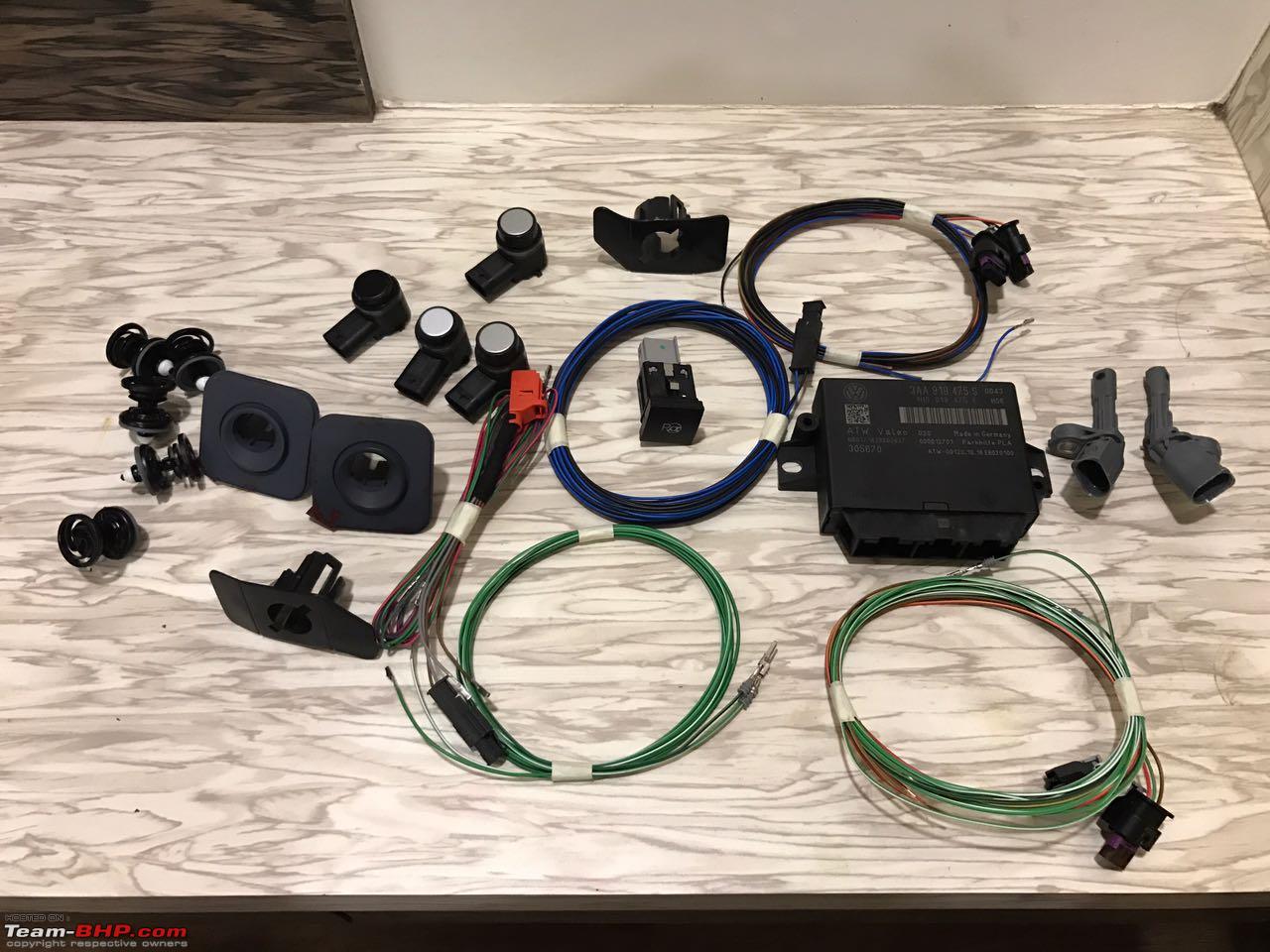
Parts you need :
1. PLA 2.0 module - 3AA 919 475 M.
2. Ultra-sound PLA sensors - 1T0 919 297 A - 2 for front and 2 for rear.
3. Brackets for PLA sensors - 3C0 919 493-4 - 4 nos. (notice that front sensor brackets are angled)
4. Rear ABS sensors - 2 nos - WHT 003 857-8 A.
5. Wiring harness.
6. Park Assist switch.
You can buy whole kit from aliexpress. Just ask seller about compatibility regarding your car MY. You can use this kit if you already have 8K OPS in your car.
PLA 2.0 kit - OEM PLA 2.0 for Jetta IMPORTANT NOTE -
When you order this kit, choose
"with 8 sensors" under color name.
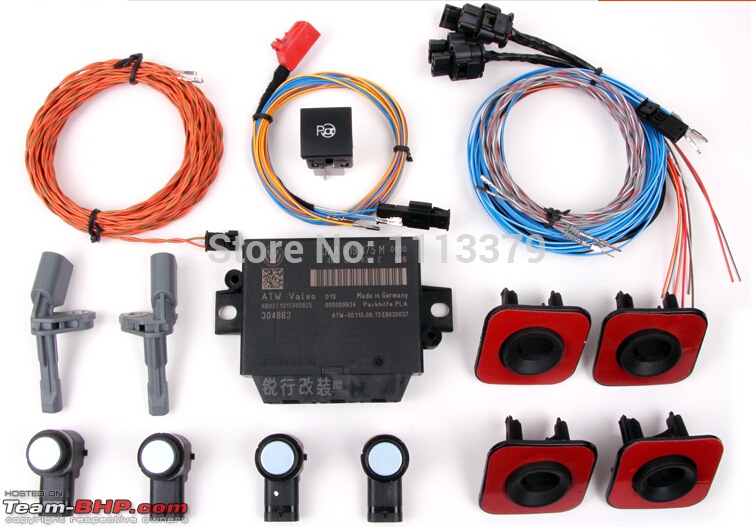
image source - aliexpress
Kit was received as described. Package was received within a week. Seller is very helpful and he even shared wiring diagram.

But before all the hassle, let's see why we should install this
cool retrofit.
1. 360 OPS (boon when you're surrounded by traffic)
2. This system can park in very tight space, which we can't do.
3. Looks really cool if you've installed.
4. It can Park/Unpark so even a newbie can use it.
5. Even best valet can't beat this accurate system.
So overall you can go for this retrofit without any second thought.
Before you plan to install this retrofit, make sure you have good technician with you and all the necessary tools handy.
Tools required
* T20 torx bit
* T25 torx bit
* M12 XZN triple square spline bit socket (steering wheel remover)
* ratchet or screwdriver
* Utility knife
* Tapered drill bit (11/16 size)
* Trim removal tools
* Heat Shrink
* Fabric/friction tape
* Electrical tape
* Masking tape
* Double sided sticky tape
* Terminal pin removal tool
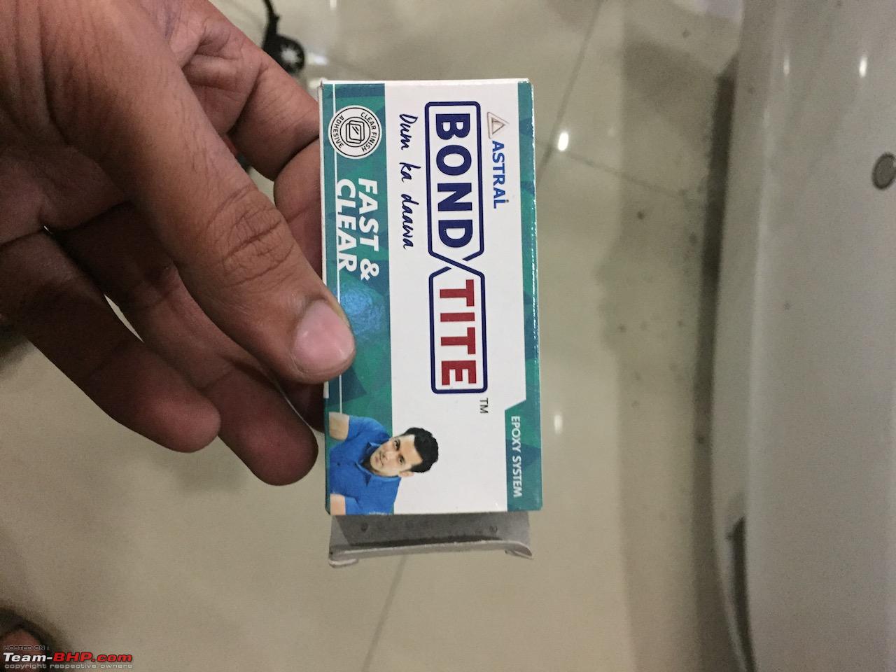
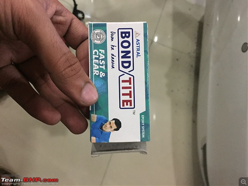
* adhesive (bond tite)
* Steel fish tape
INSTALLATION :
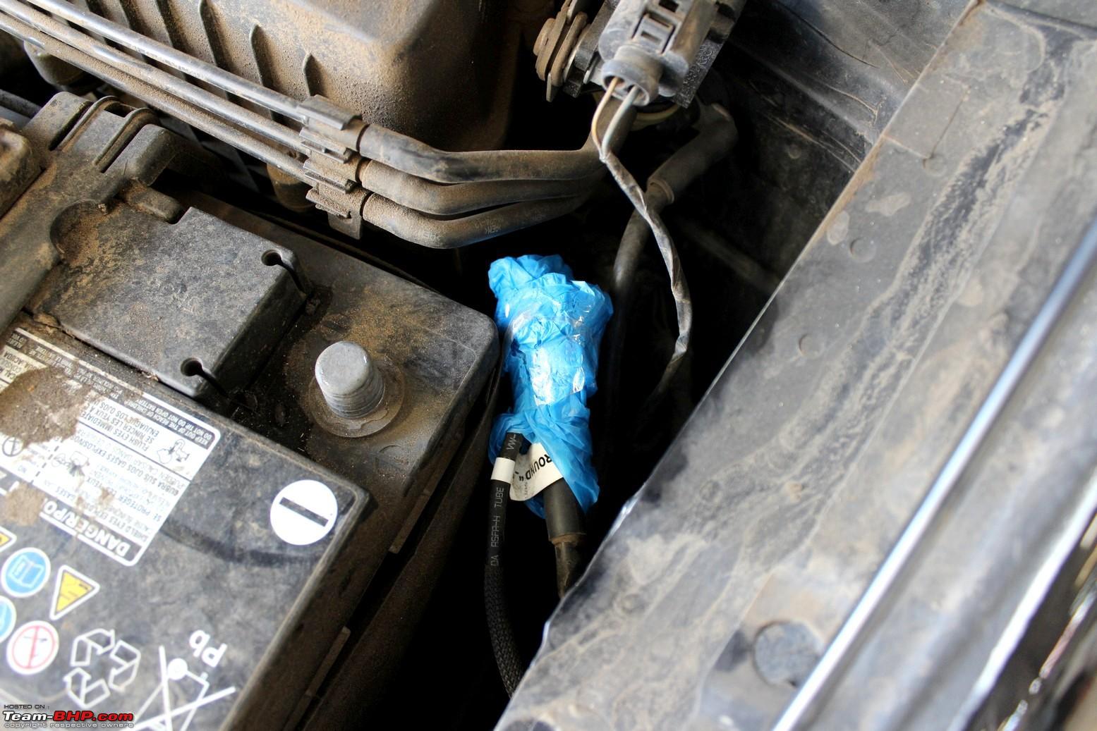
First of all remove Positive terminal from battery and insulate it with electrical tape.
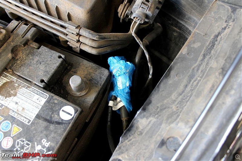
pic courtesy - Team-BHP
We will divide installation process in following steps.
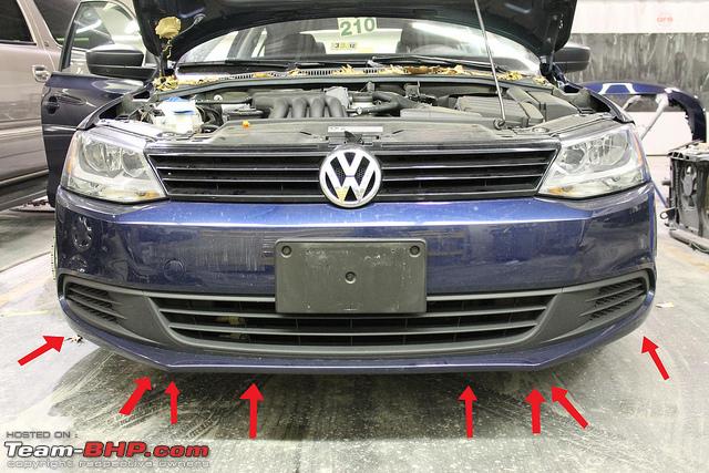
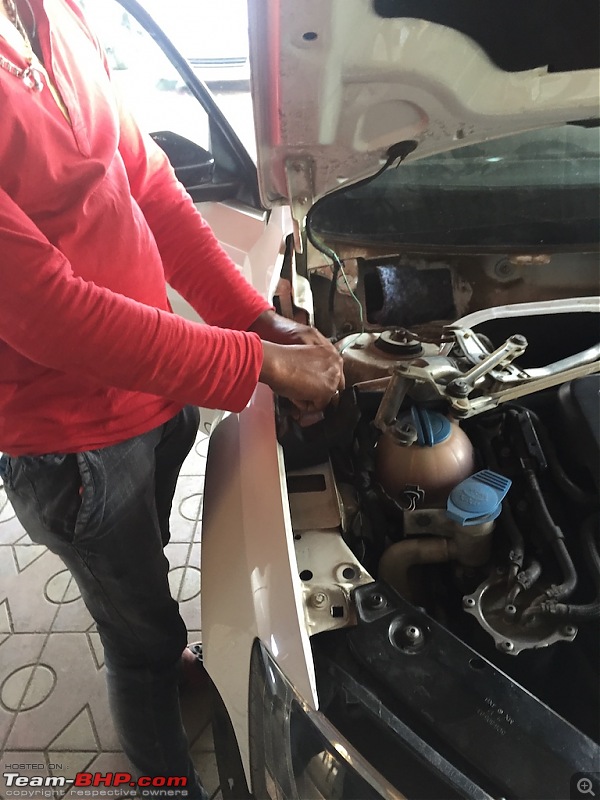
1. Remove front bumper
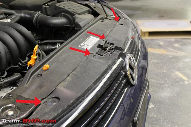
* First of all pop up the hood. Now with the help of T25 Torx bit , detach front grille by removing 4 screws.
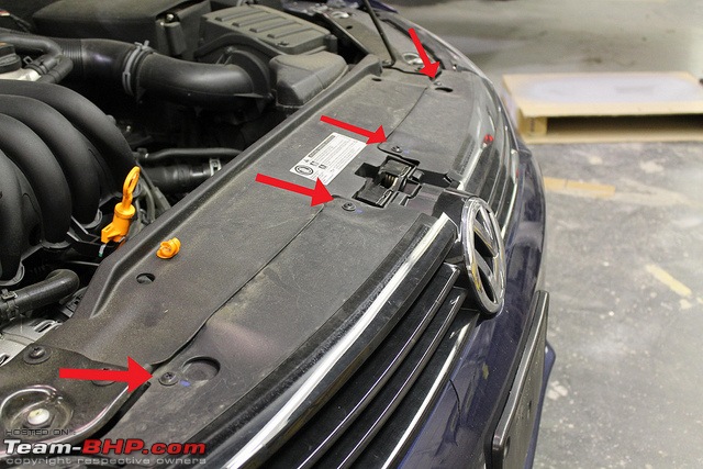
image source - vwvortex
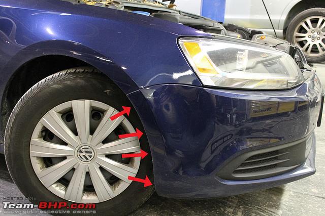
* Remove 4 screws from fender near wheel arch using T25 Torx bit. Make sure to check size of the screws and put them in right spot again.

image source - vwvortex
* Remove one screw from bumper near wheel arch which holds assembly in place.

image source - vwvortex
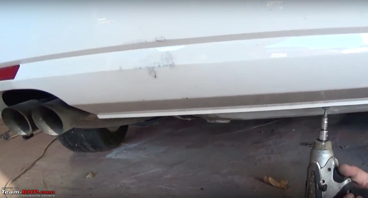
* Remove 8 screws from the bottom of the bumper using T25 Torx bit.
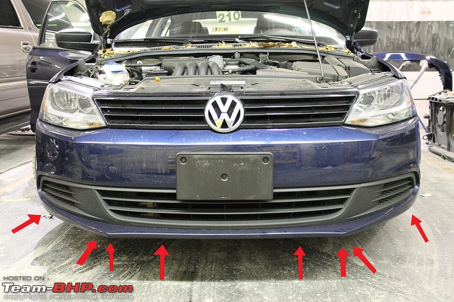
image source - vwvortex
* Now with the help of other friend, remove front bumper slightly and remove OPS as well as fog lamp socket. Put it somewhere safe where it doesn't get damaged.
2. Remove rear bumper
I have found video for this on youtube. You can checkout, else I have taken screenshots from video for step by step guidelines.
Rear bumper removal
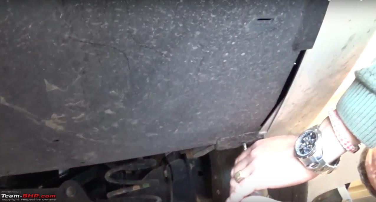
* Remove 3 screws from fender side of rear bumper using T25 Torx bit.

image source - youtube
* Remove 3 screws from underneath of bumper on the right side using T25 Torx bit. Remove black plastic.
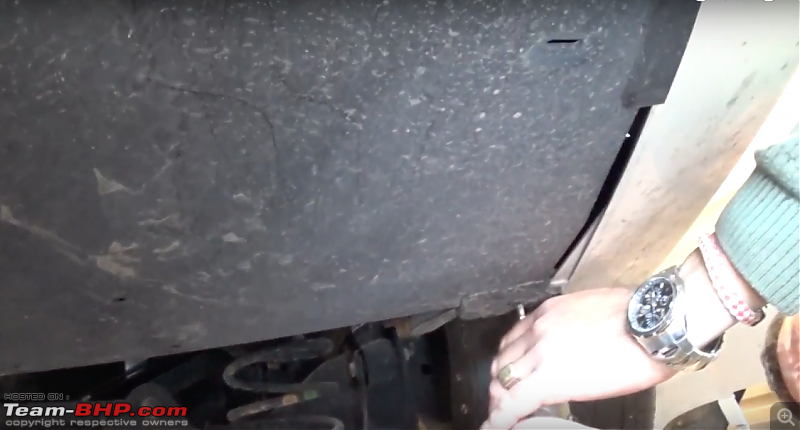
image source - youtube
* Remove 4 screws from the bottom of bumper using T25 Torx bit.
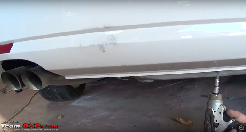
image source - youtube
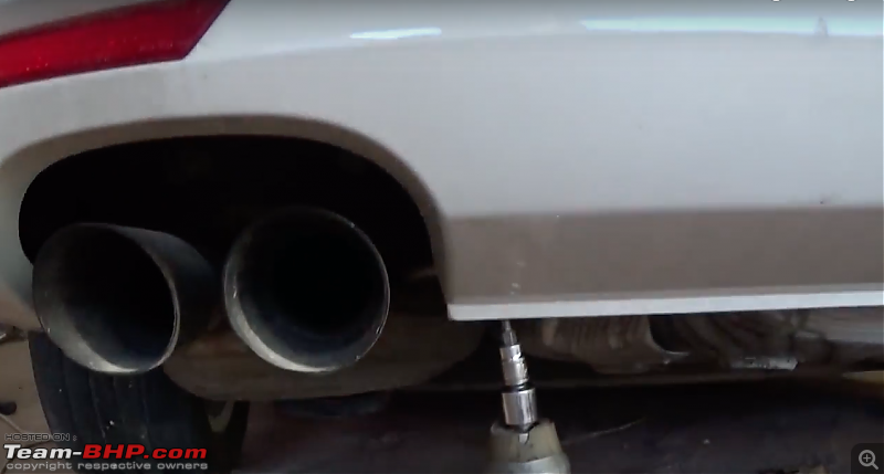
image source - youtube
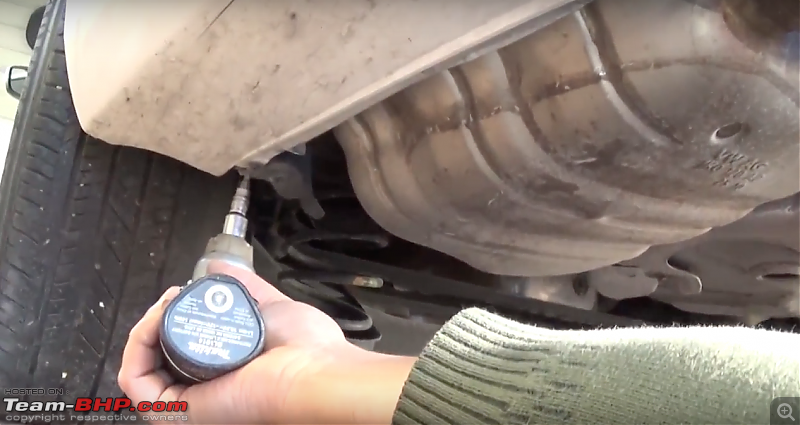
image source - youtube
* Now most importantly, there is a hidden screw inside fender panel. Remove that panel and remove one screw using T25 Torx bit with extender on both the sides.
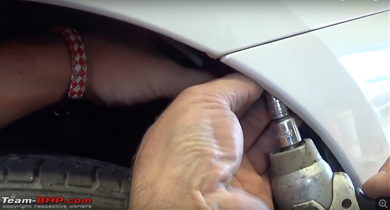
image source - youtube
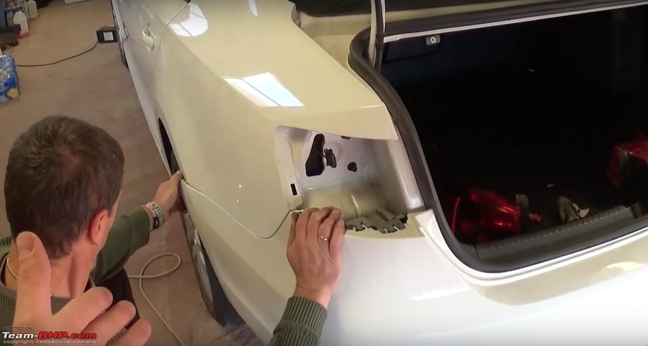
* Now remove
Tail-light assembly. Open trunk and remove cap inside boot. You will see white plastic screw with spring around it. Just unscrew it and easily remove tail-light assembly. Unplug tail-light connector.
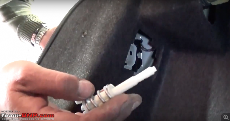
image source - youtube
* Remove screw under tail-light assembly using T20 Torx bit. And unclip bumper from 2 clips on each side.
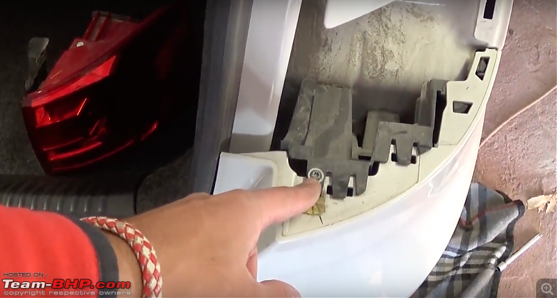
image source - youtube
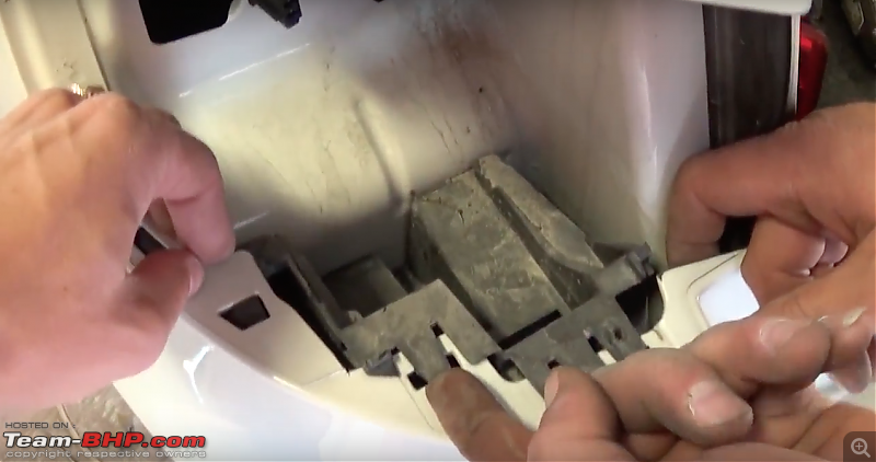
image source - youtube
* Now slide bumper backwards starting from fender side. Gently get it out.
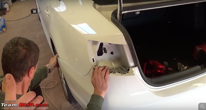
image source - youtube
* When you try to remove bumper, you will feel that there is something holding it. Just remove that one screw on each side using T25 Torx bit with extender.

image source - youtube
* Now remove whole bumper and put it safe somewhere so it doesn't get damaged.
3. Locate 8K OPS Module
Now this is the step where everybody will think why I chose to install this kit in the first place. As
Tanveer_2558 suggested in his
thread, it's a real headache to locate 8K OPS module.
According to other forum threads, it's located under following locations.
1. In the trunk.
2. Below wiper assembly.
3. Below glove-box.
4. Behind instrument-cluster (most difficult one).
Removed wiper assembly but no signs of module.
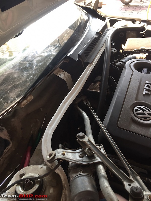
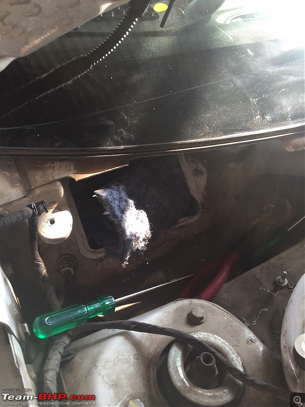
We tried everywhere and finally found it behind instrument-cluster. In order to remove that, you have to strip down whole dashboard.
DISCLAIMER : Before you start removing dashboard assembly, make sure you have all the required tools handy and you have a good technician with you.
INDEX :
1.
REMOVE DASHBOARD.
2.
REPLACE ABS SENSOR.
3.
INSTALL PLA SENSOR.
4.
WIRING.
5.
CODING.
REMOVE DASHBOARD :
Now step by step remove whole dashboard assembly. If you're not sure about this process then take some professional help.
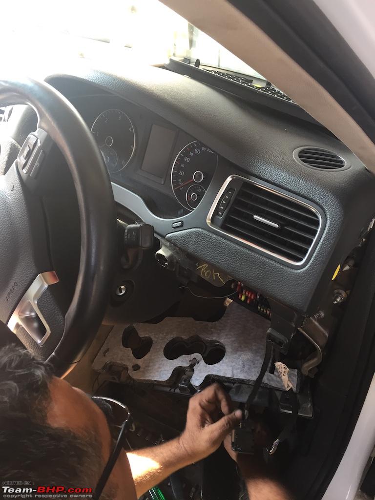
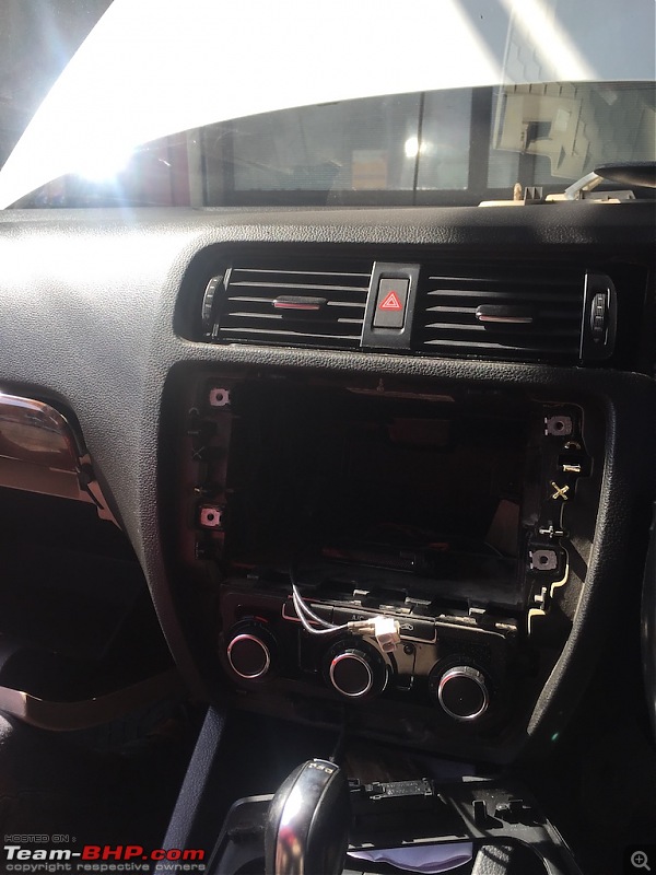
Start off by removing headlight switch panel. Just pull off 'FAUX' wood panel.
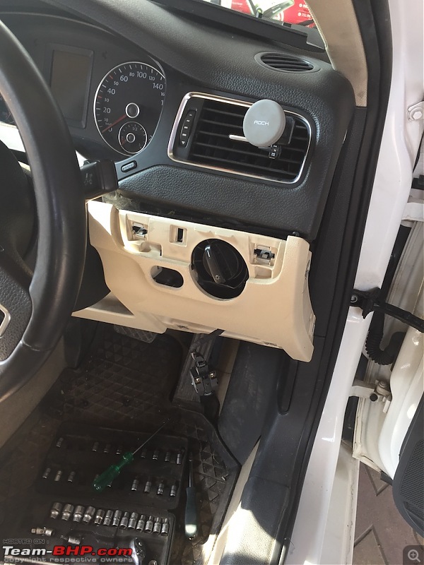
Remove headlight switch. Put it at "0" position and press it. Just regulator slight right and switch will come out easily. Remove side panel.
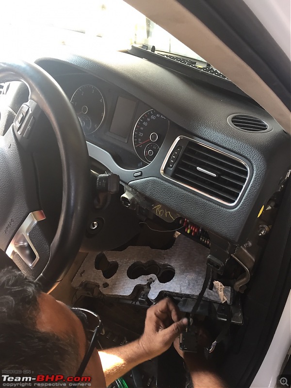
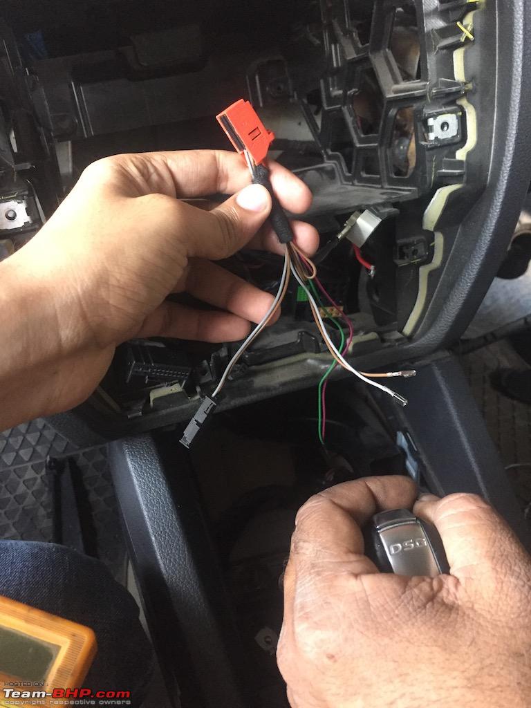
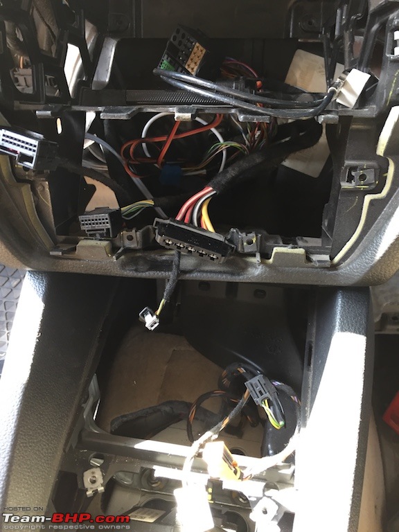
Now remove HU. Disconnect all connectors and put it somewhere safe. Remove HU panel by disconnecting 'AIRBAG WARNING LIGHT' connector.
Now using
Gannu's DIY for removing instrument cluster method, unscrew 2 screws from instrument cluster.
Disconnect 24 pin connector and gently remove cluster. Put it safe.
Now disconnect glove box and gently remove it.
After you remove whole glove box, it will look like this.
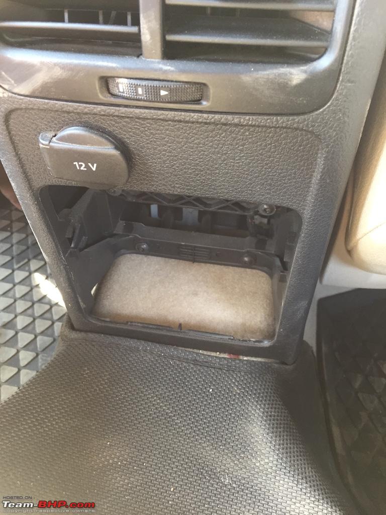
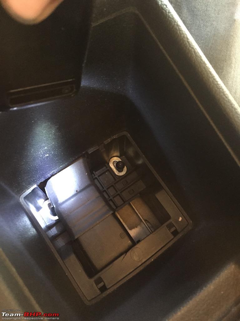
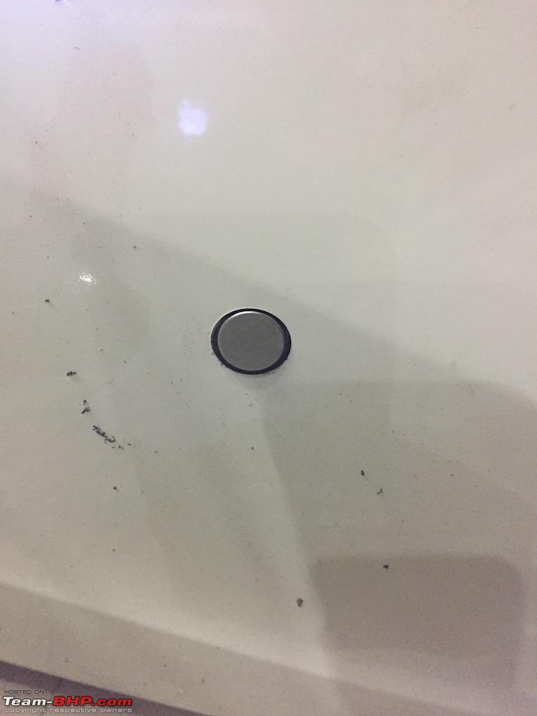
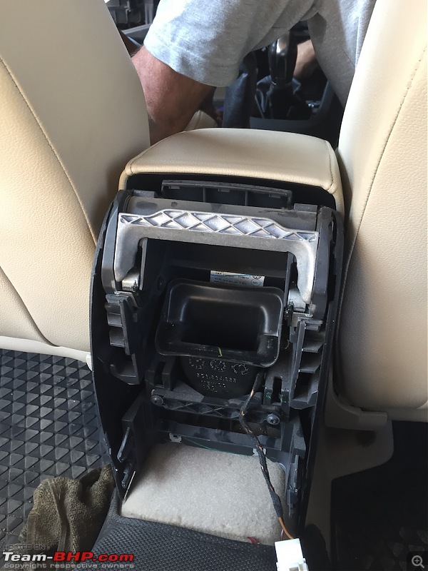
Remove panel near gear level, which has Park Pilot switch. Disconnect connectors.
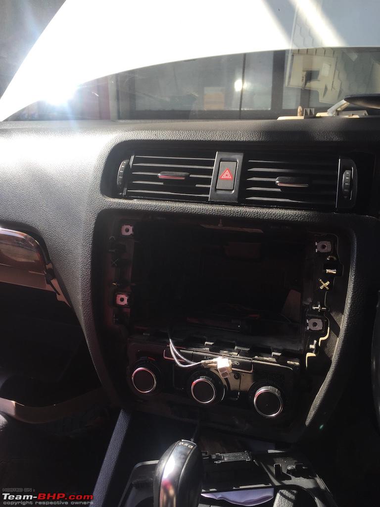
Now remove HVAC (AC console) panel. Disconnect connectors.
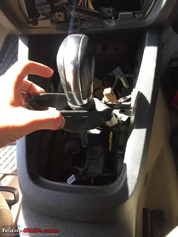
Remove gear lever leather cover.

Now in order to remove upper dashboard, we need to remove centre trim (gear lever) so that dashboard can be pulled back and we can remove it easily.
So start with rear AC console. Unscrew it.

You will see there are 2 screws inside centre armrest, unscrew them.
Remove rear AC vents. Now you will see there will be some play with whole assembly. We will use that as our benefit and will lift upper dashboard.
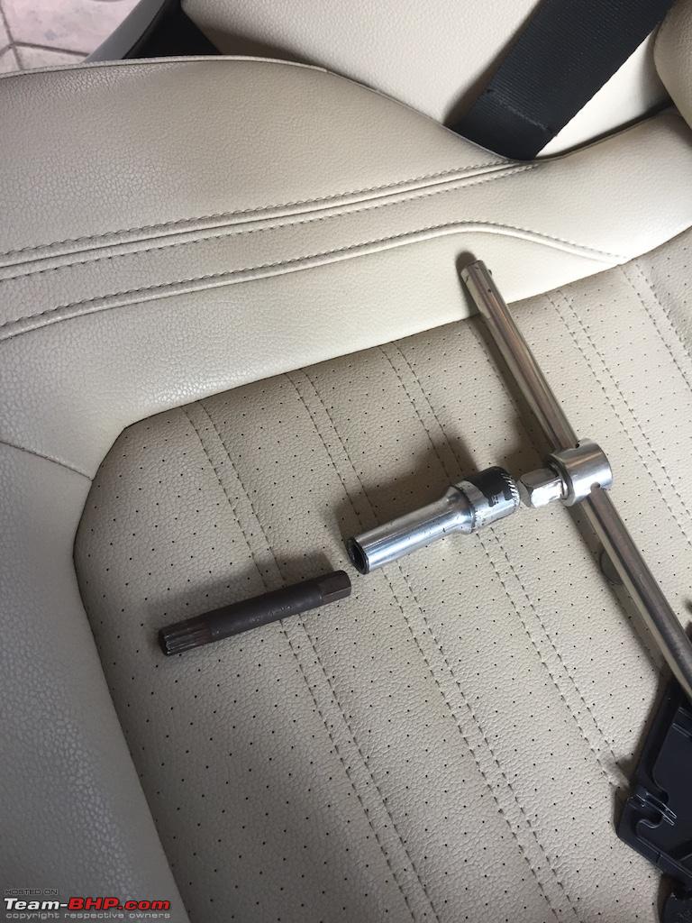
Now we will have to remove steering wheel.
DISCLAIMER : If you don't have any idea how to do this, then don't attempt this step alone. Use some professional help if needed.
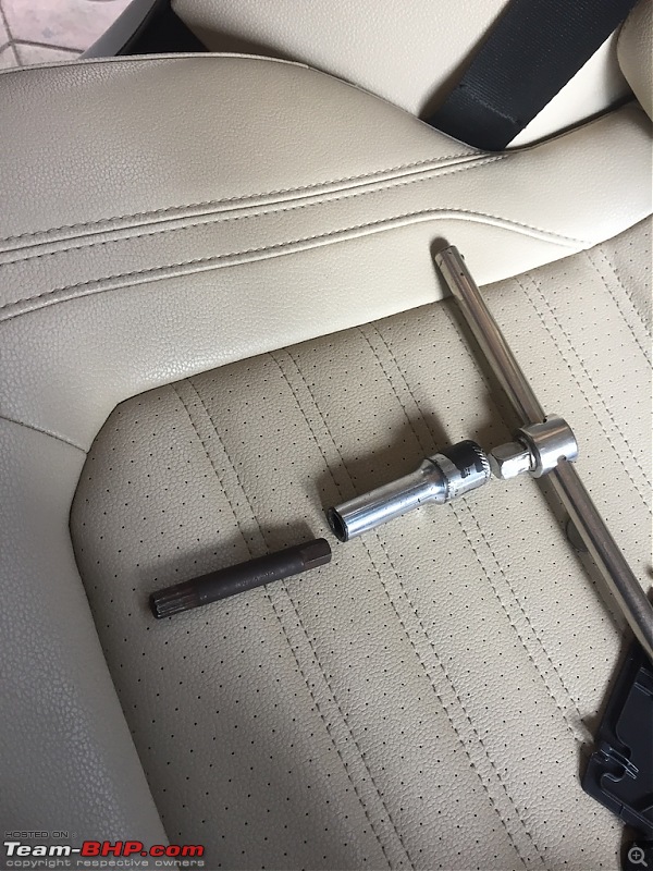
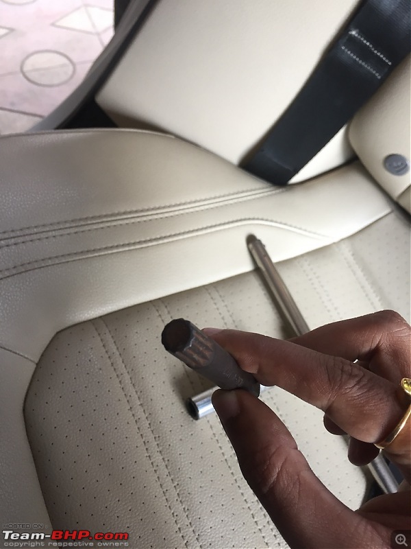
Tools :
1. M12 XZN triple square spline bit socket.
2. Ratchet with extension.
For detailed guidelines please follow
Gannu's steering removal thread.
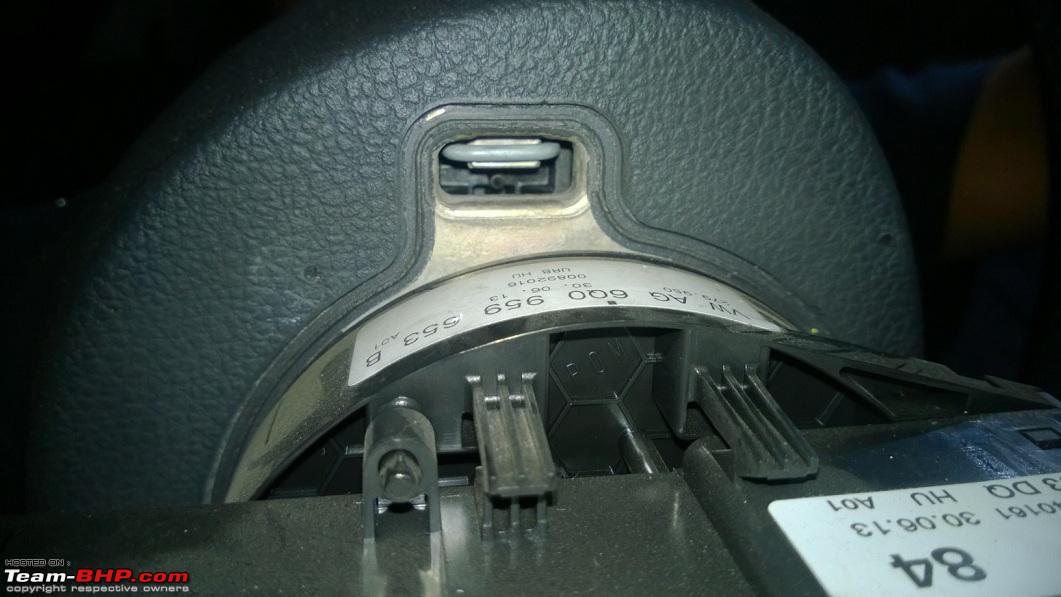
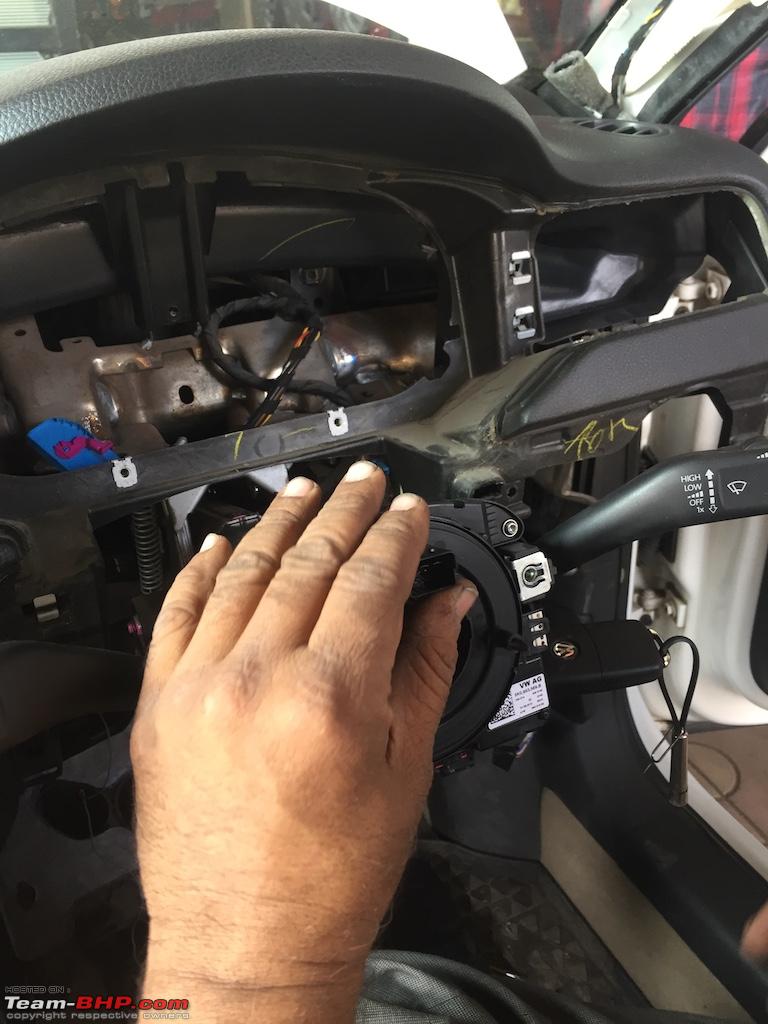
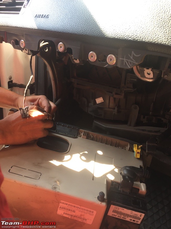
First of all we have to remove airbag from the steering wheel. Before that remove upper trim of steering column.
Now rotate steering wheel about 90 degrees right. And if you look at back you will see a clip like this.
pic courtesy - Team-BHP
Now using flat-head screw driver push this clip downwards to detach it.
Rotate steering to its normal position. Now again rotate it about 90 degrees left. repeat above steps and detach another clip.
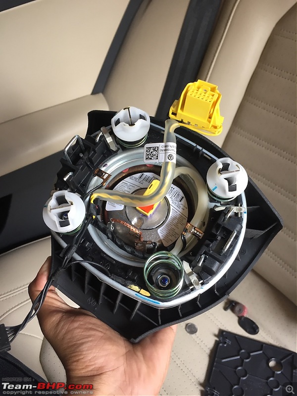
Now that clips are detached. Remove airbag assembly carefully. Disconnect yellow connector and black connector.
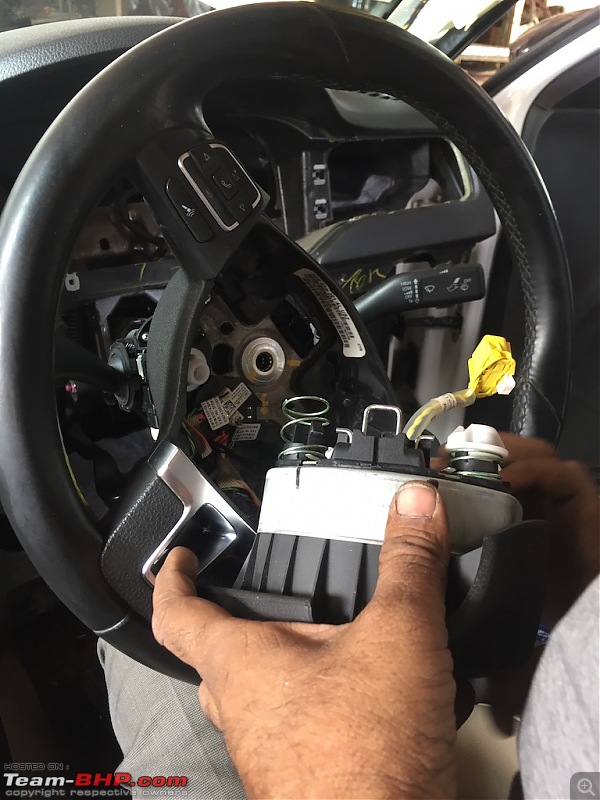
Put airbag safe.
Now rotate steering wheel to centre position and using described tool remove centre screw.
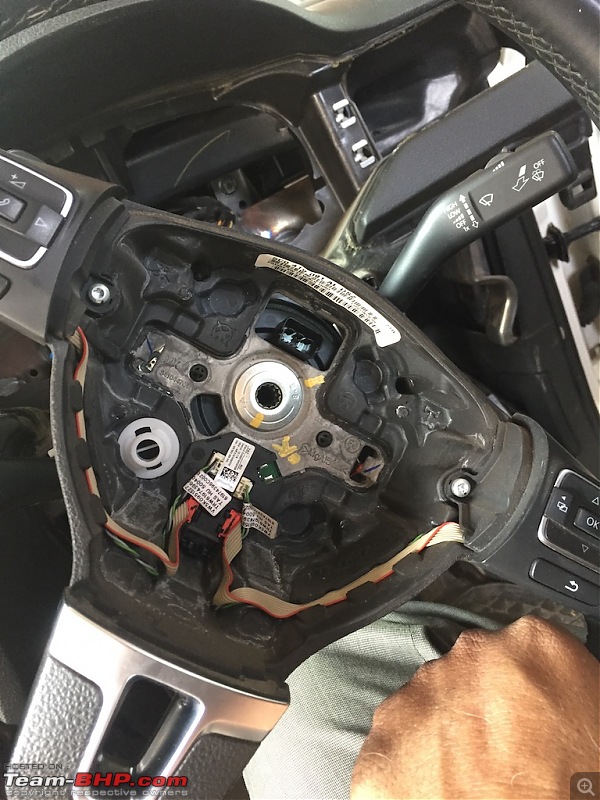
Now make sure that steering is locked in centre position. 2 slots should be aligned in position.

Now pull steering out and put it safe.
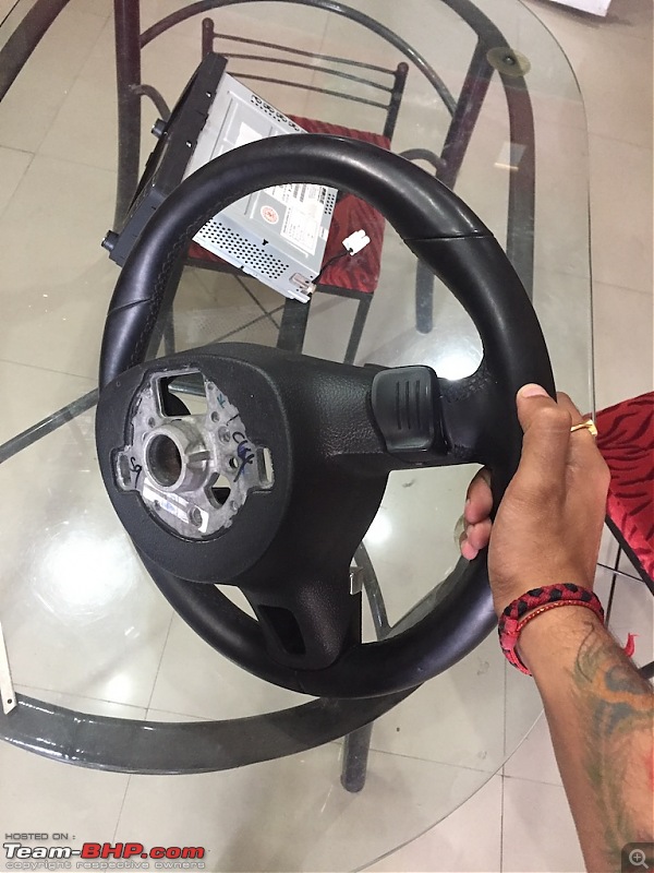
Now remove both stalks by unscrewing 2 screws on each side.
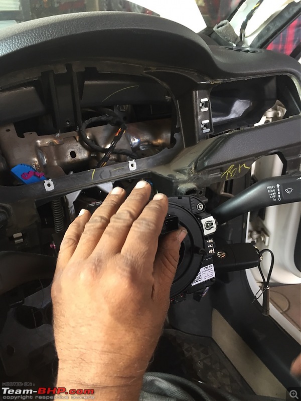
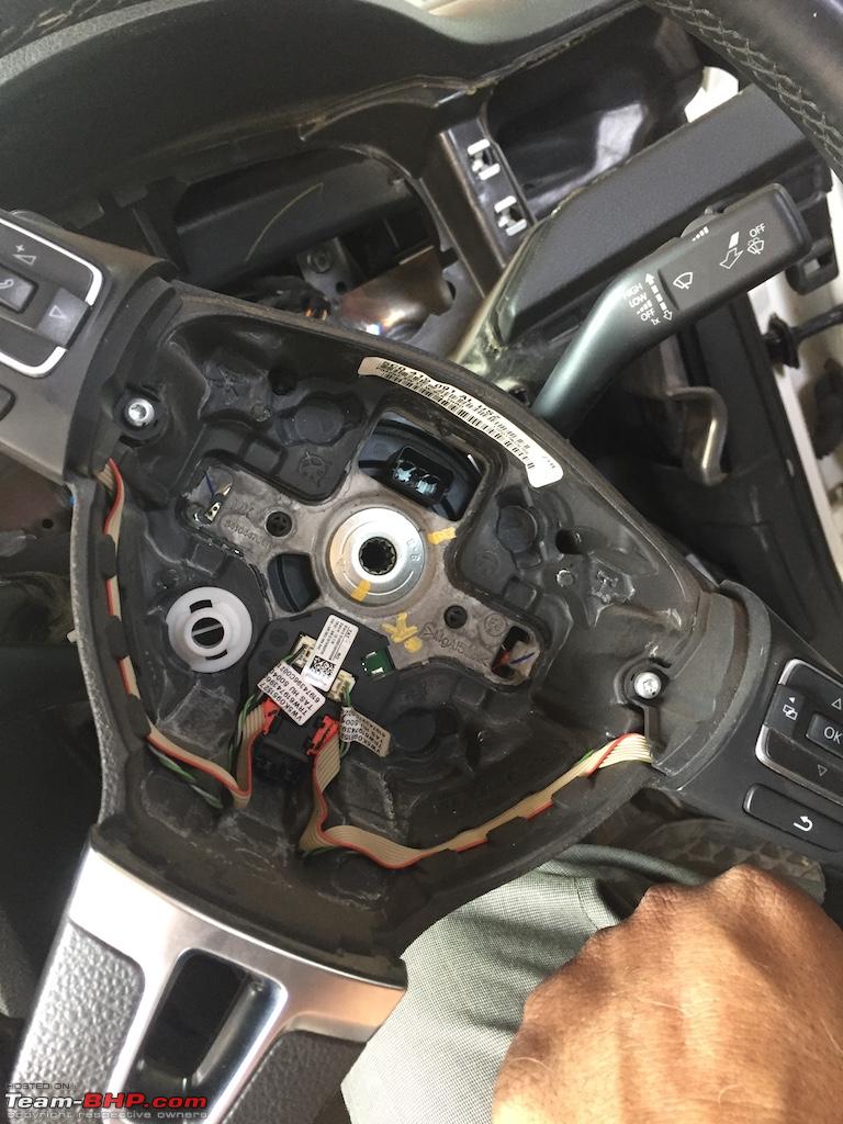
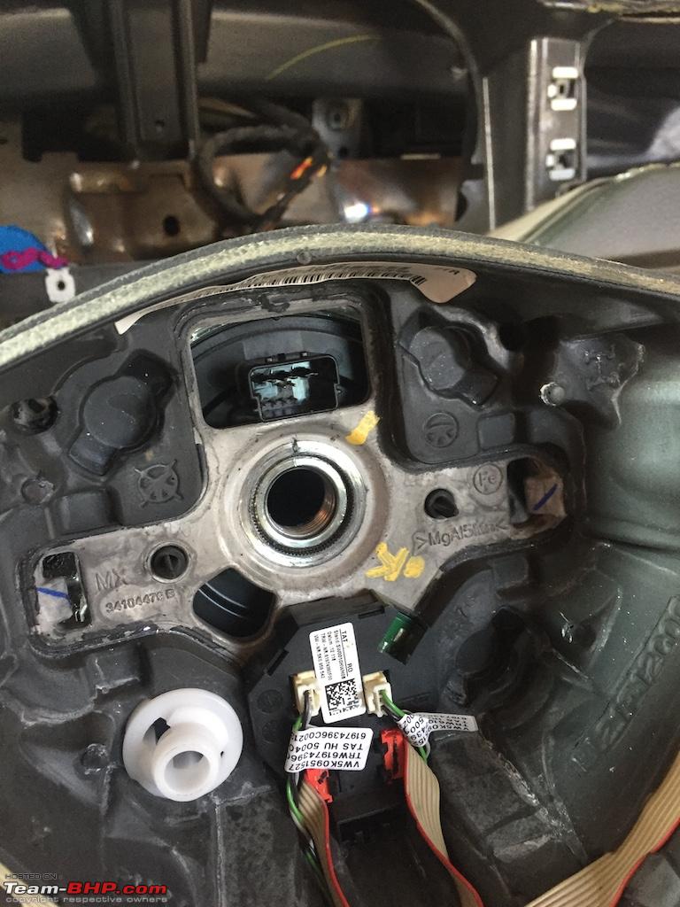
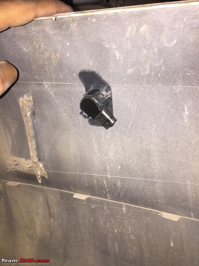
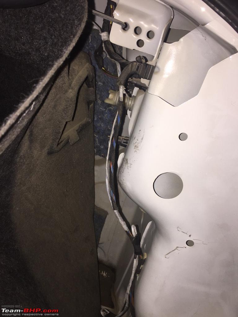
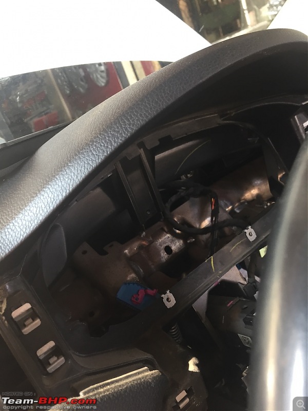
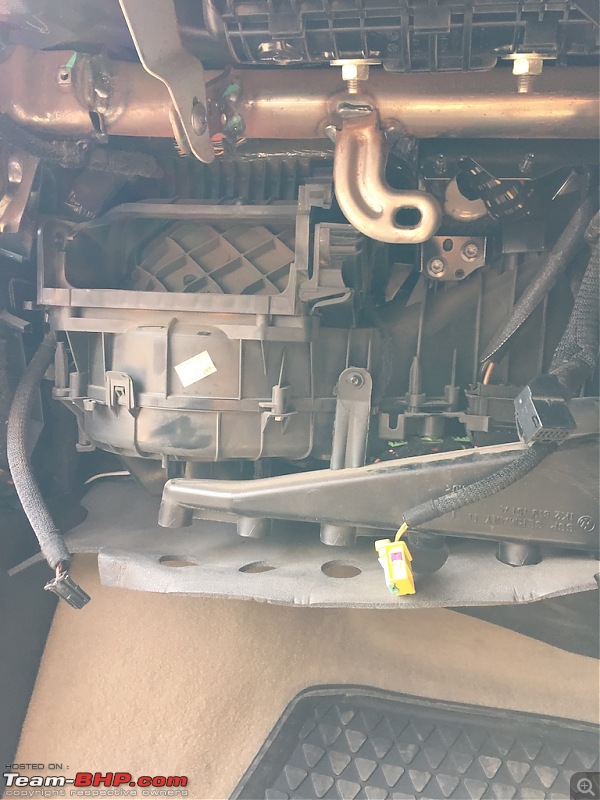
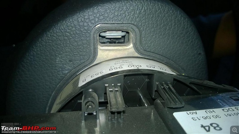
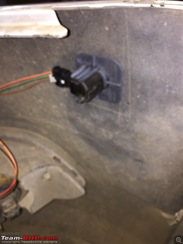
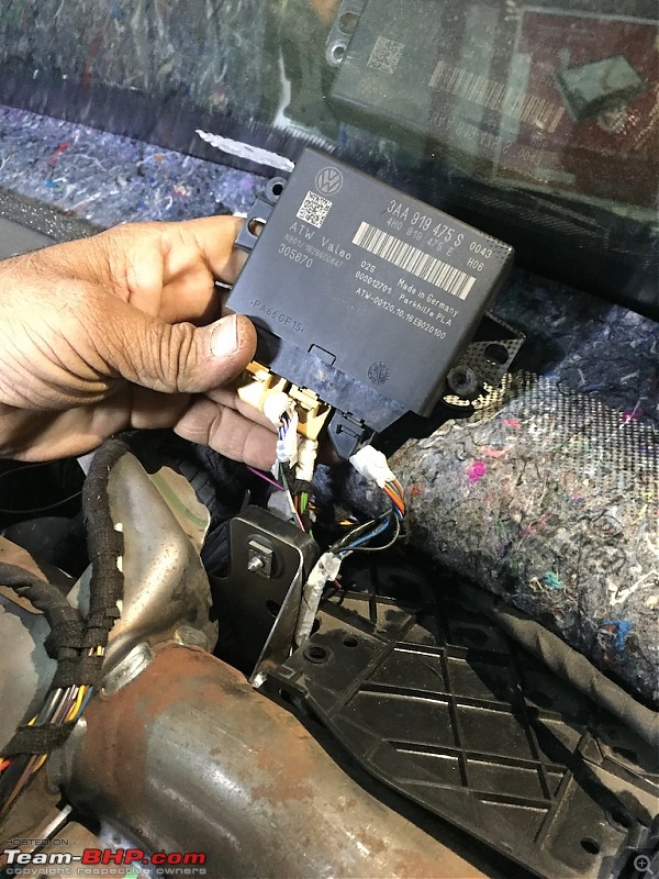
Now with the help of a friend lift dashboard a bit and you will see the culprit a.k.a
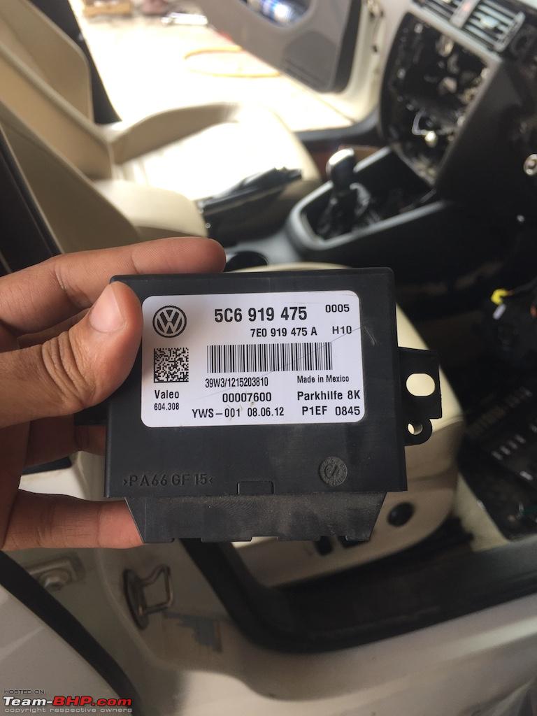
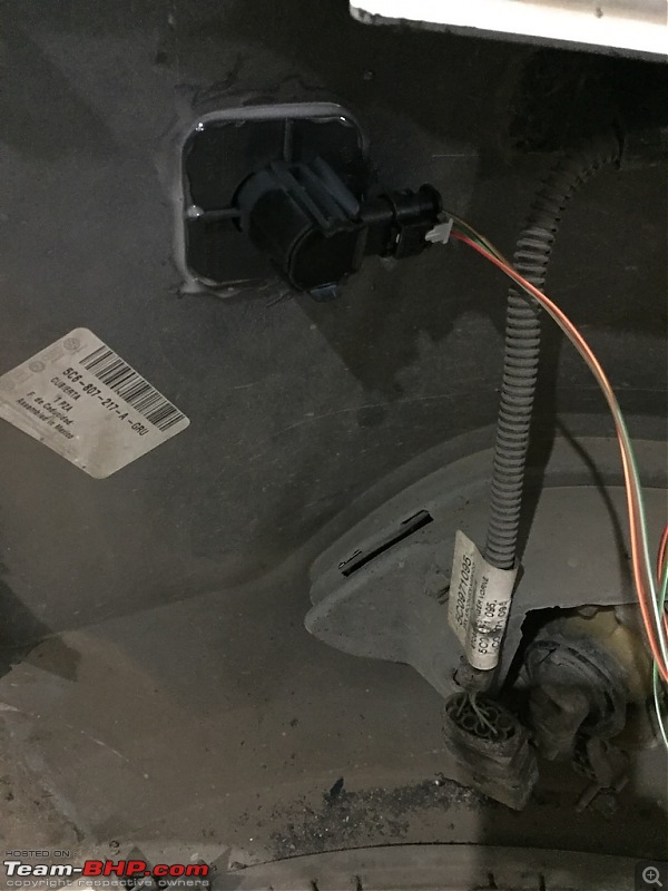
8K OPS. It is located on the right side of dashboard.
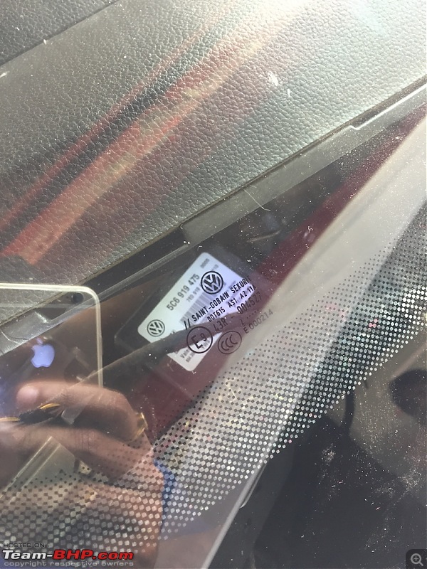
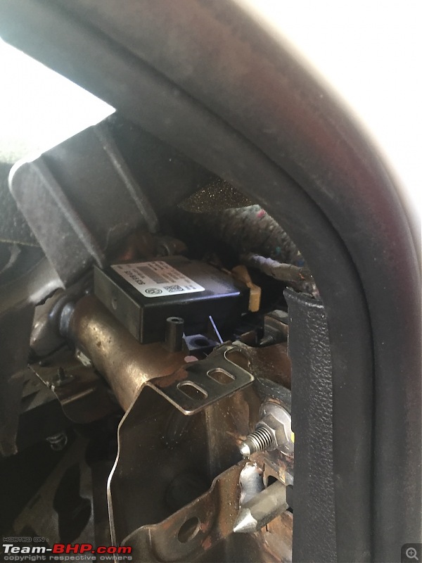
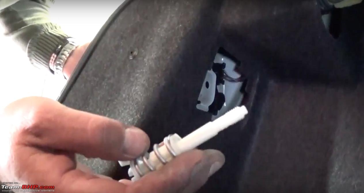
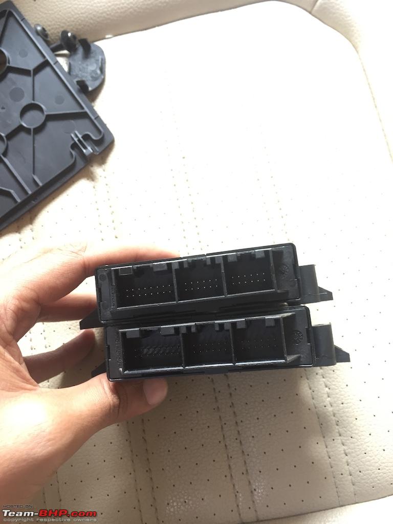
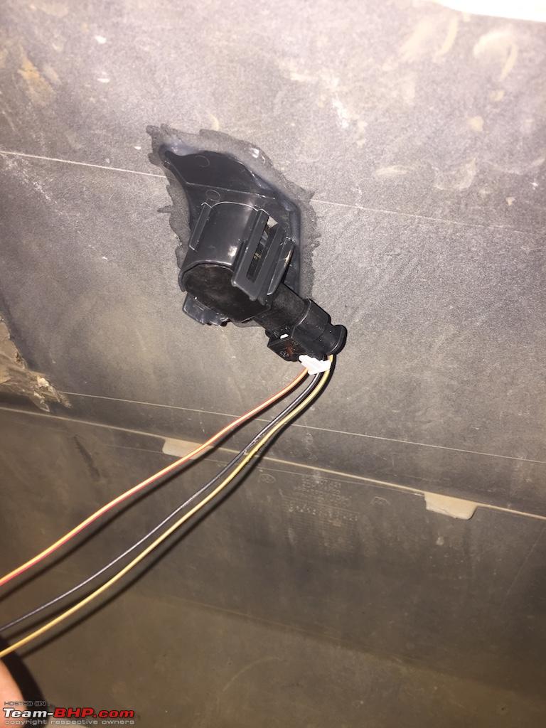
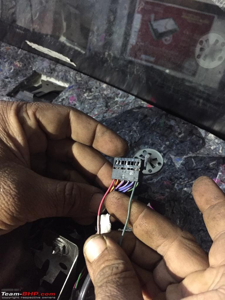
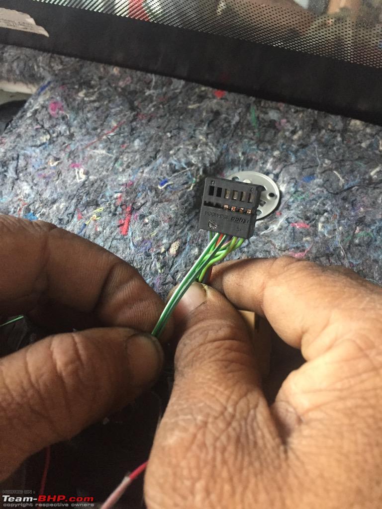
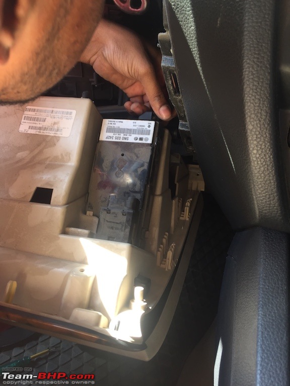
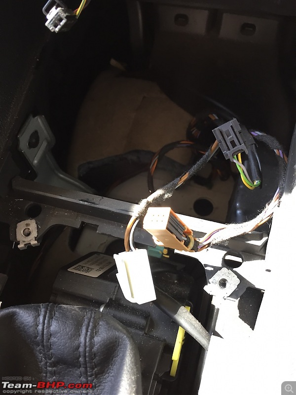
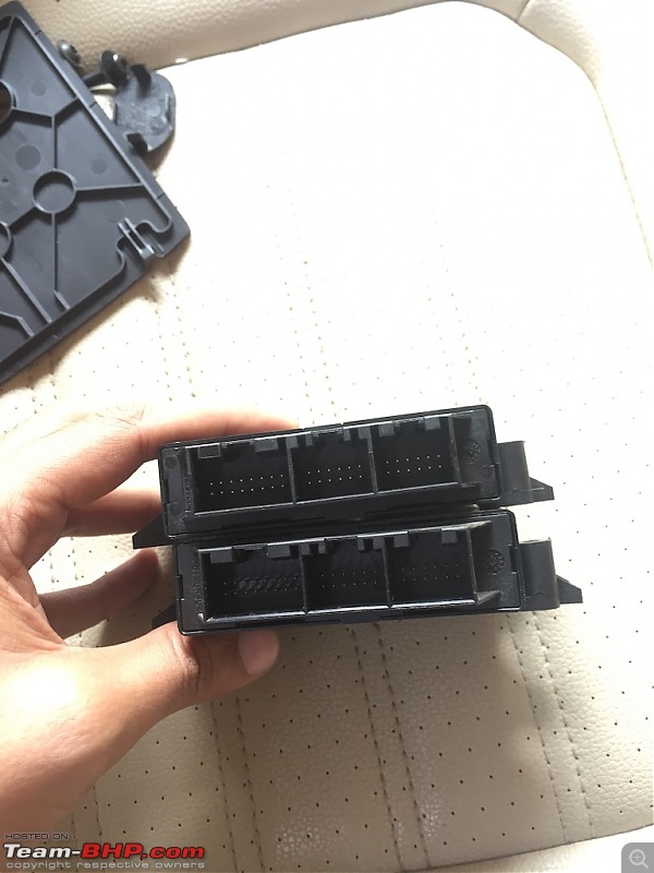
Now disconnect 16-12-12 pin connector from OPS module and get it out.

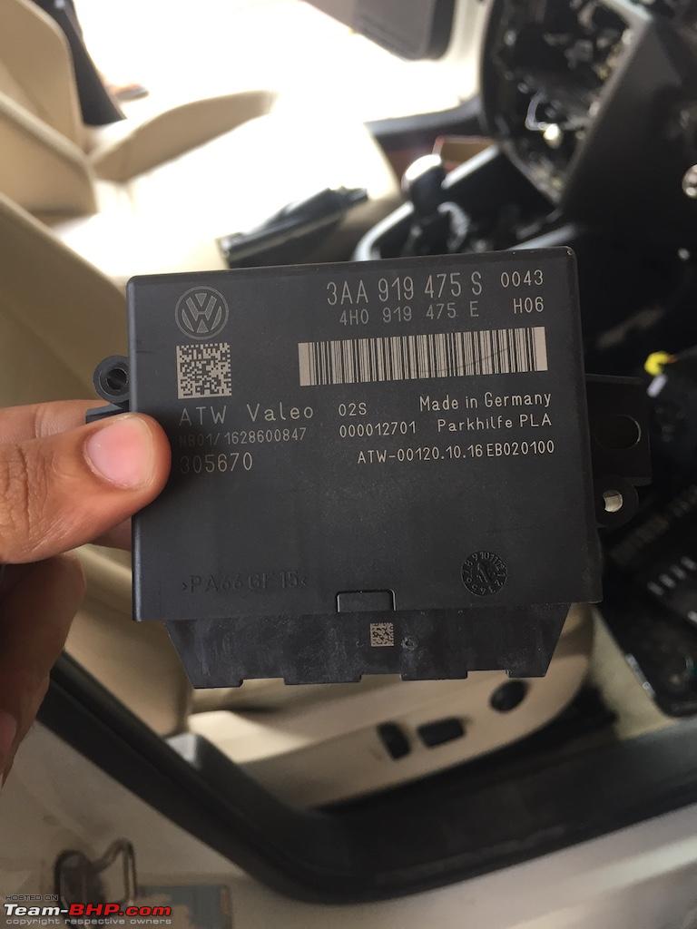
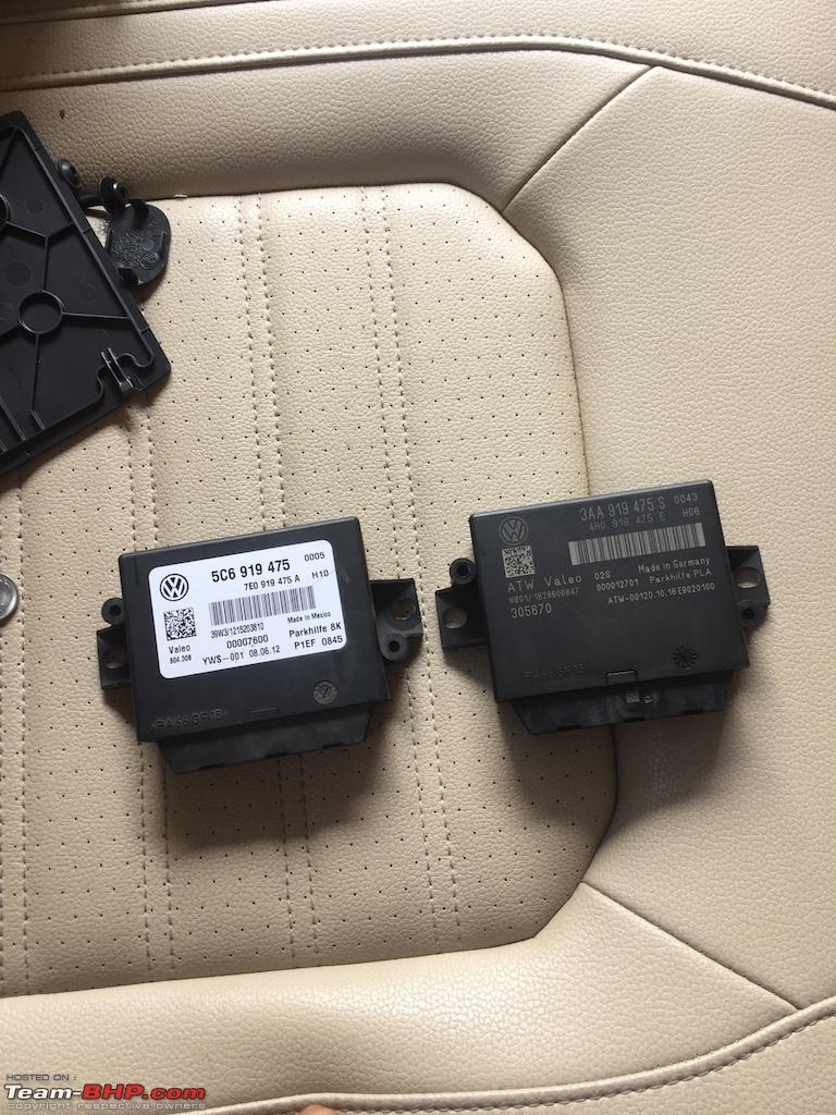
We have the new PLA module which has similar connector pins. Both look identical.
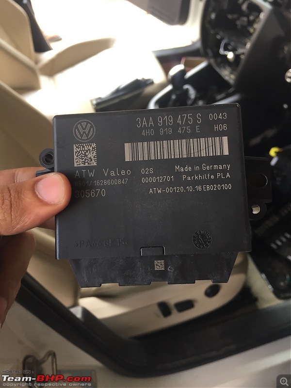
Side by side pic of old and new modules. (left - 8K OPS , right - PLA)
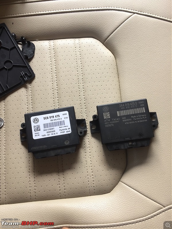
Pin layout of both modules are exactly the same. Though we will have to rework on connectors in coming steps.
REPLACE ABS SENSOR :
Now we have to replace ABS sensors from rear wheels.
Basically these are similar sensors but, new sensors are more accurate.
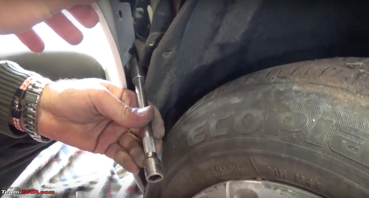
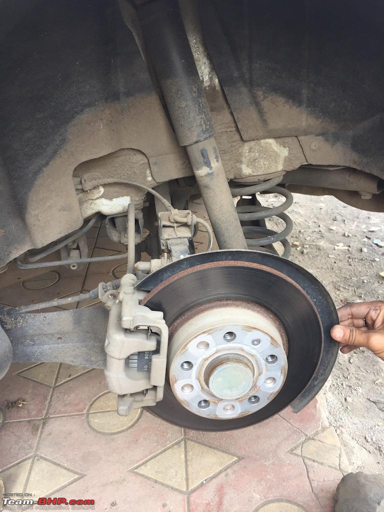
First of all by using hydraulic jacks, lift the car.
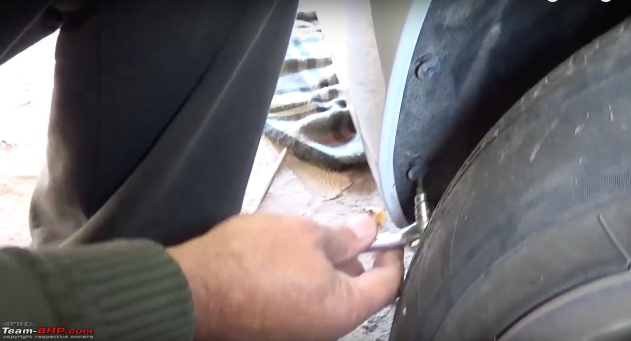
Now remove rear left tyre.
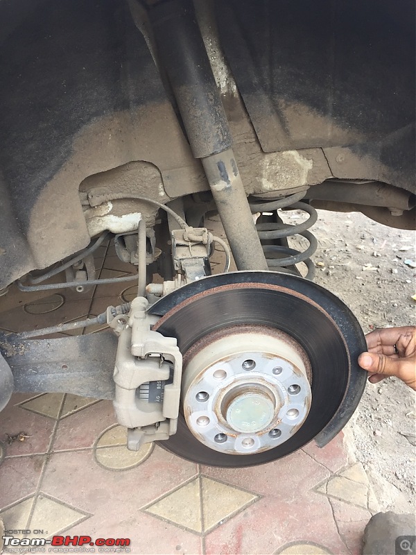
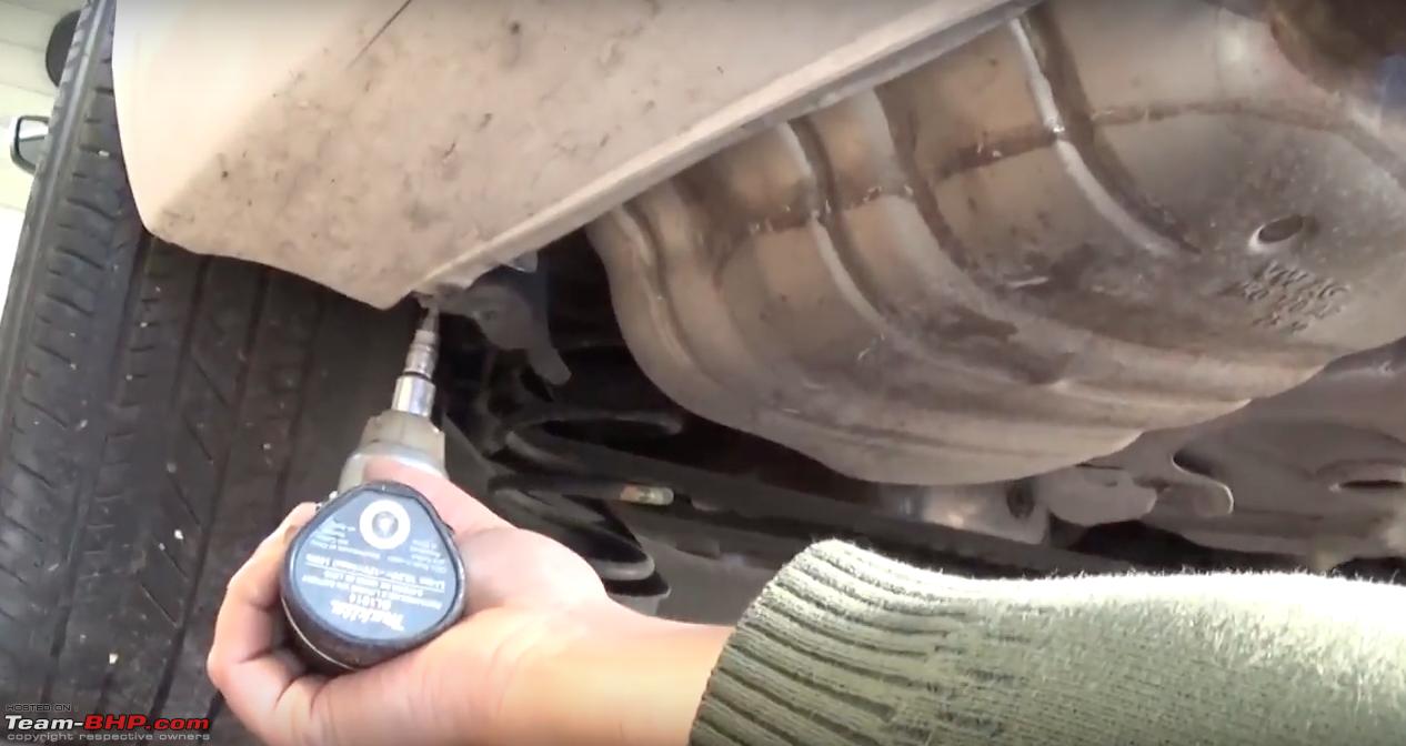
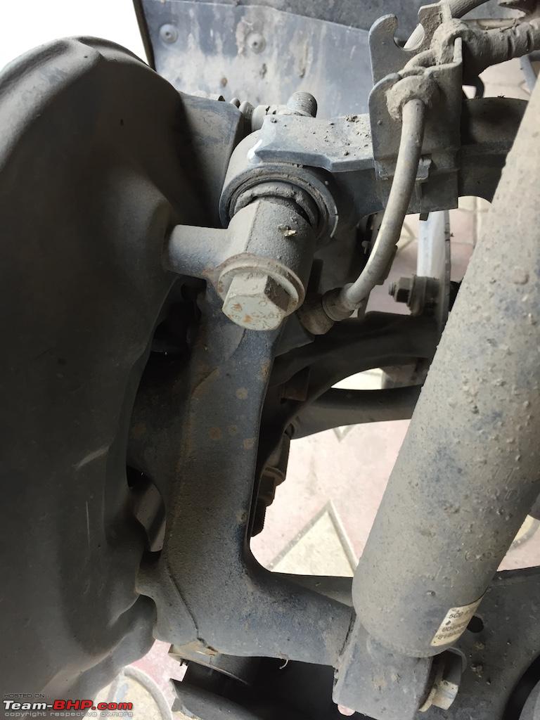
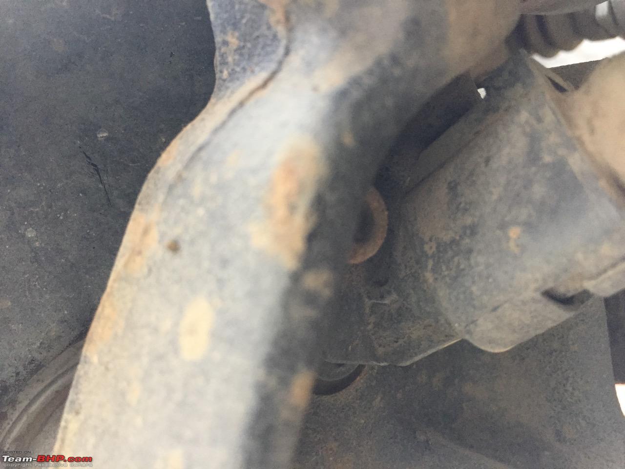
As you can see in the picture, there is cable coming out. That's our ABS sensor.
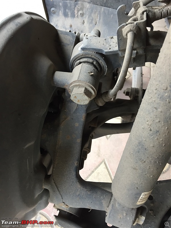
To remove that you need to unscrew that single screw and disconnect cable. This one is tricky job. You need to go underneath of the car to remove this screw and take extension ratchet to remove it.
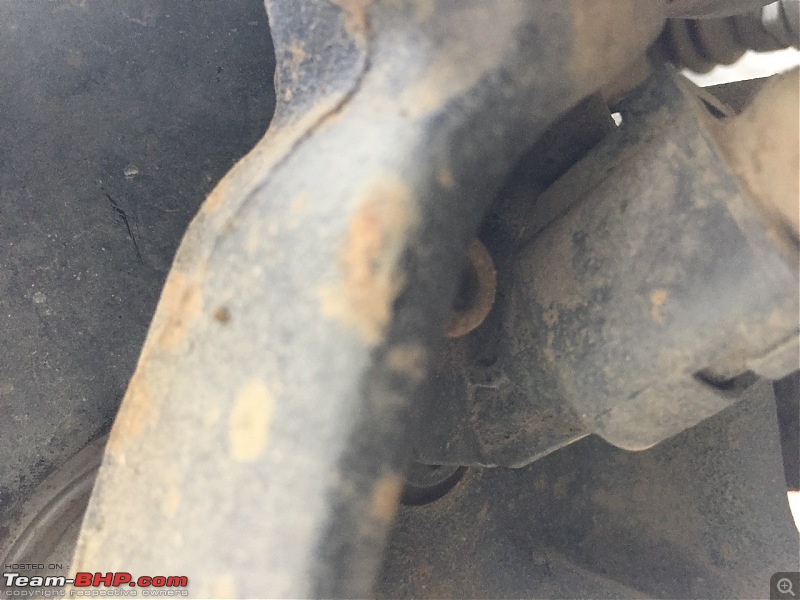
Once you unscrew it, remove upper cable using flat-head screw driver.
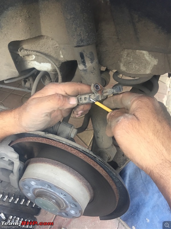
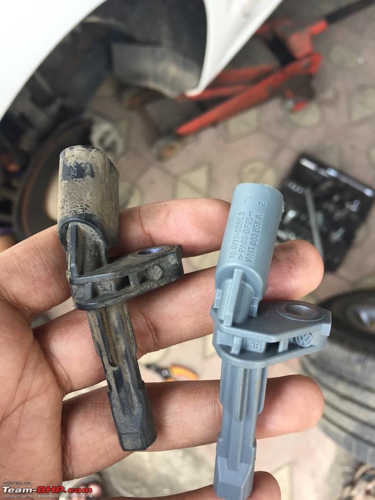
Here is the pic of new sensor we need to install.
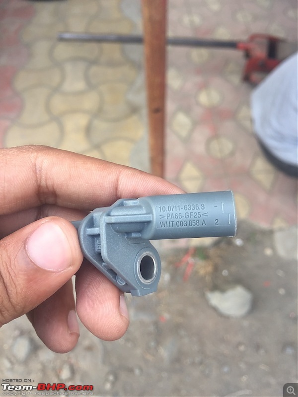
Here is the pic of both sensors. (left is old, right is new) They both look identical. The only difference is A in the end of part number.

Now install this new sensor and tighten screw.
Repeat this step for the right wheel also. And that's done.
INSTALL PLA sensor :
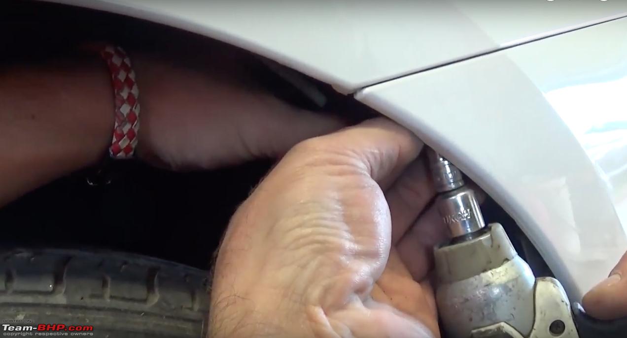
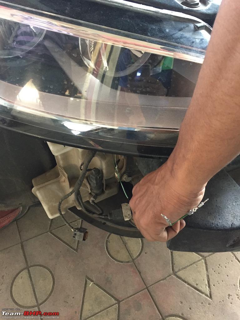
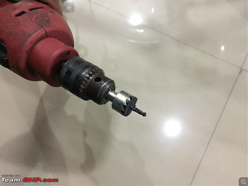
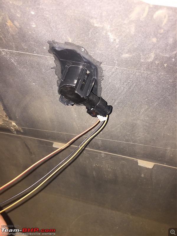
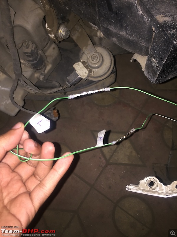
First of all we will start off with front bumpers. As we know we have to install 2 additional PLA sensors in front bumper.
Luckily VW Jetta front bumpers come with factory markings (may be for foreign markets) so we just have to drill at given markings.
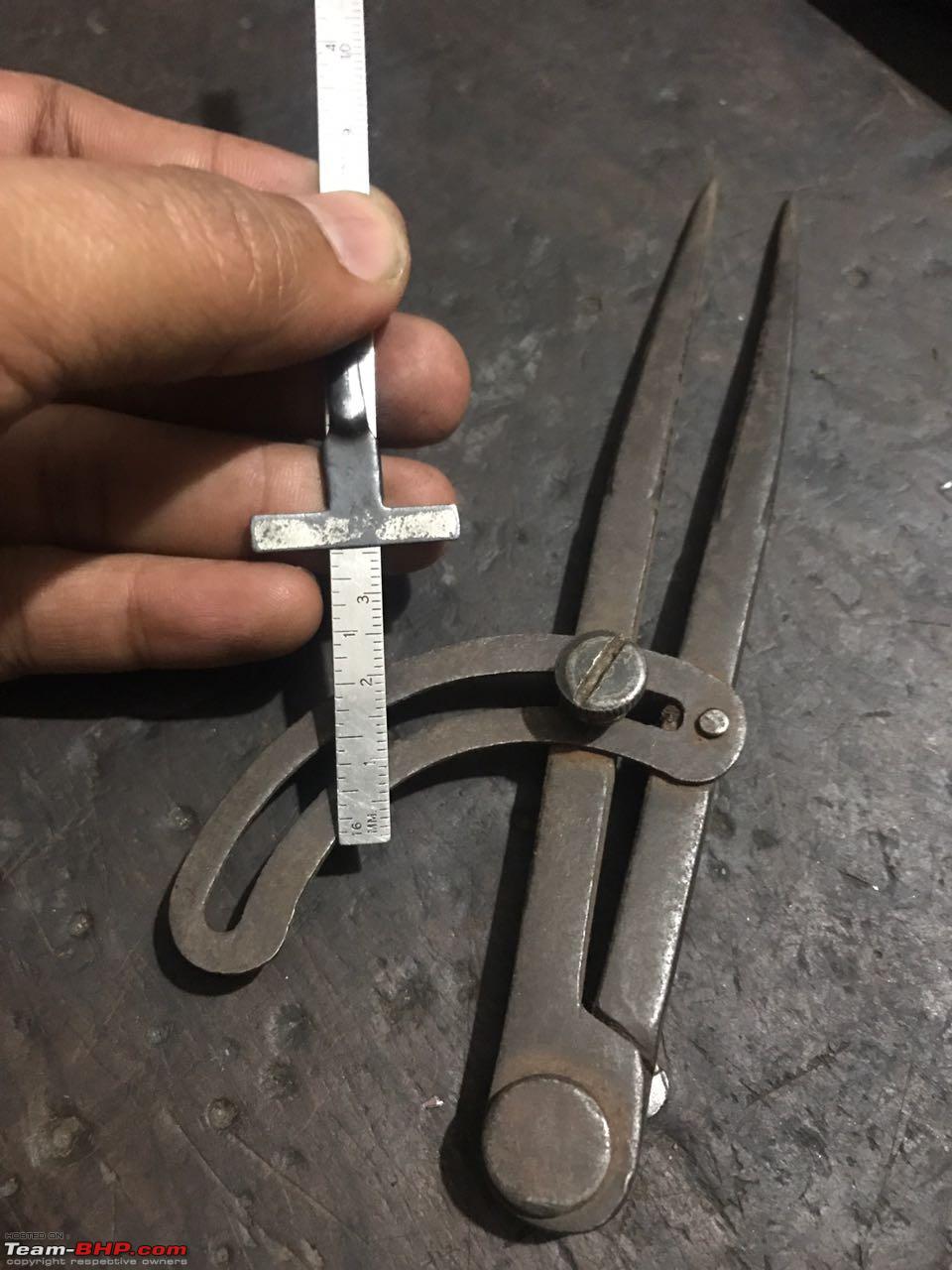
But the problem is, we couldn't find any drill bits for front PLA sensors. They are bigger and different in shape.
PLA - FRONT BUMPER :
So first we had to measure front PLA sensor.
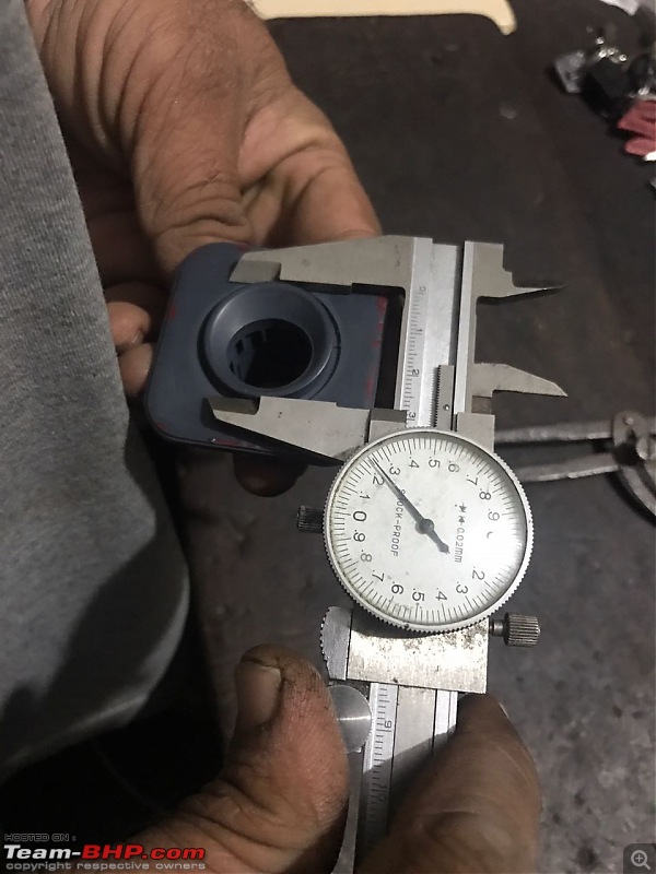
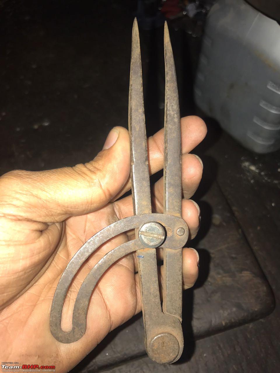
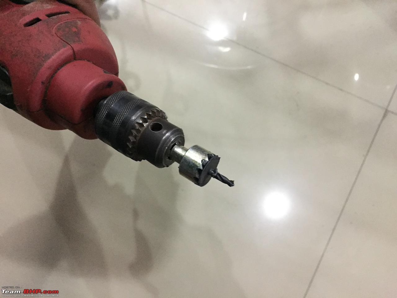
Then we used this retro tool for drilling front bumper.
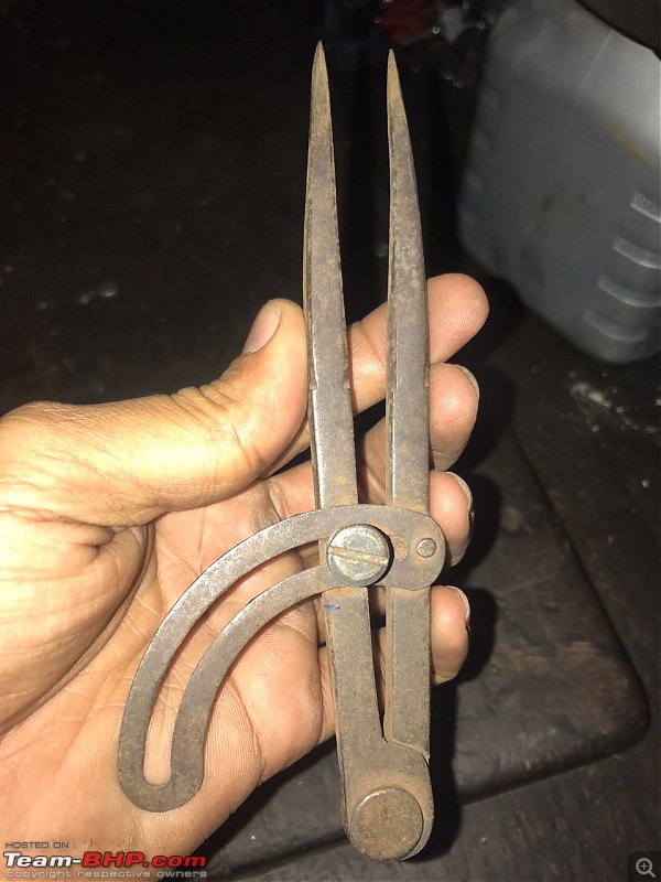
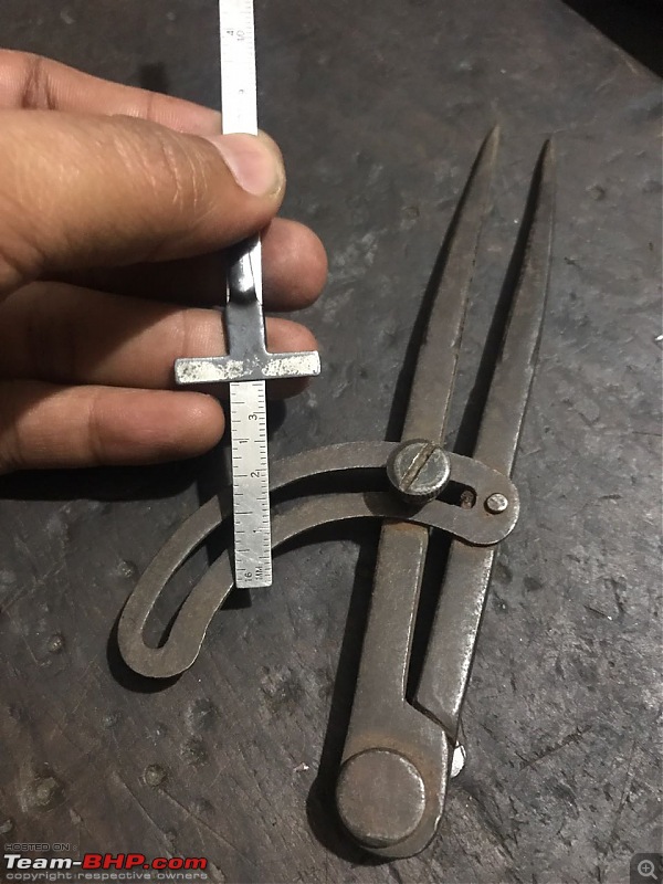
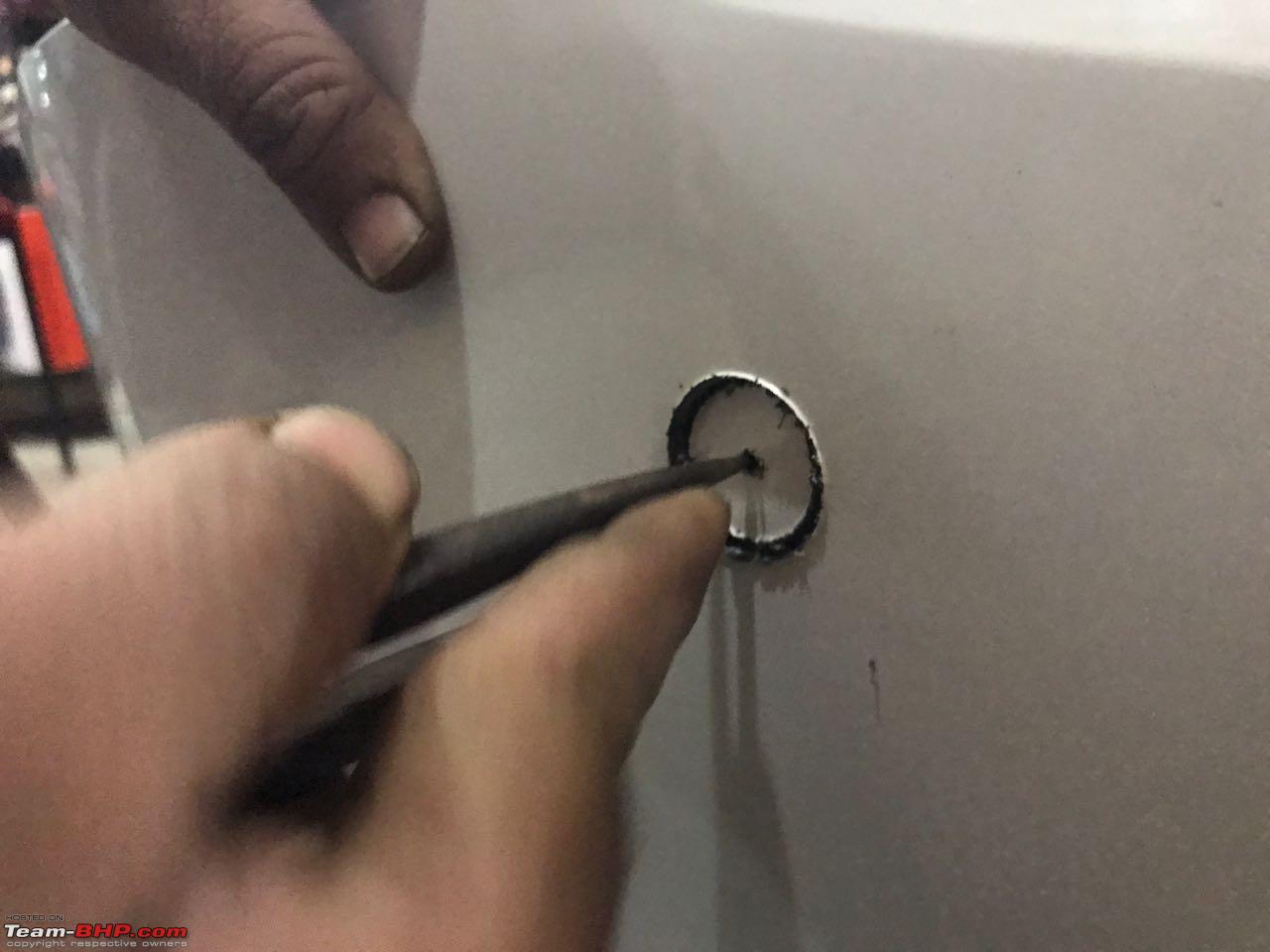
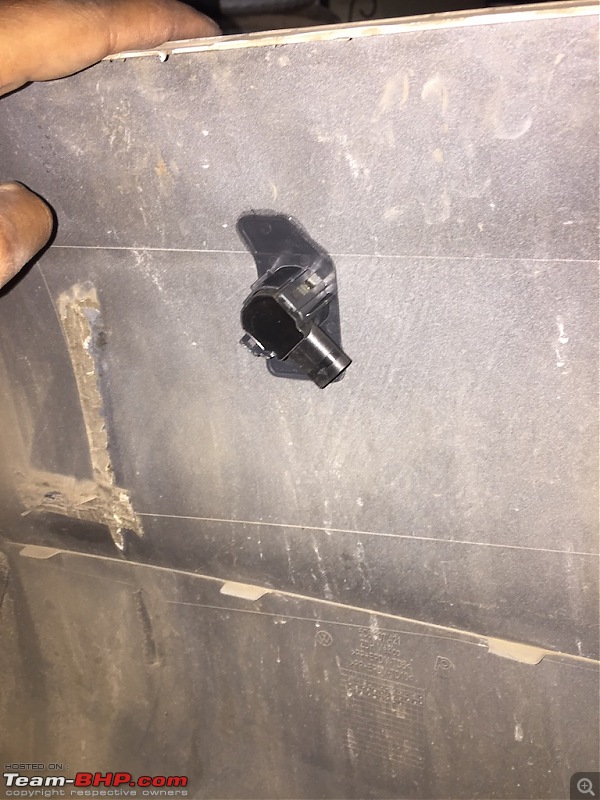
Marked centre point of circumference and rotated this tool with pressure. And in no time we got perfect hole for sensor.

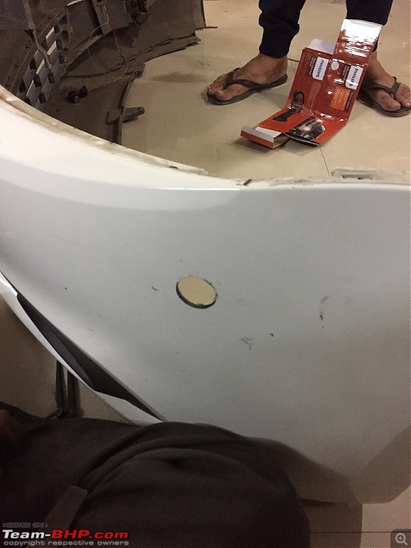
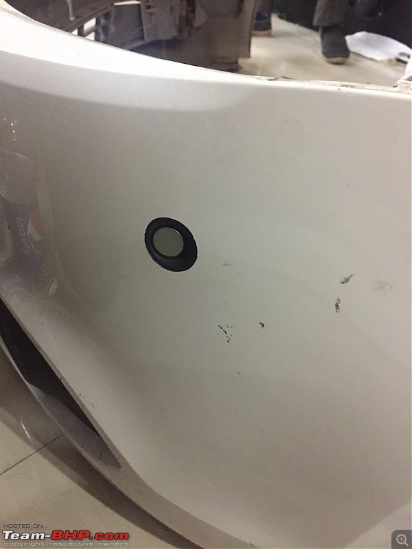
Using file tool, smoothened edges of the hole.
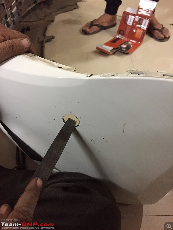
Perfect hole after filing a bit.
Now using good adhesive (we used bondtite) stick PLA sensor in hole using brackets.
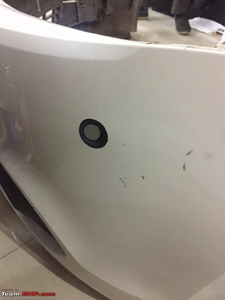
Left side PLA sensor :
Right side PLA sensor (Apple logo of my iPhone visible) :
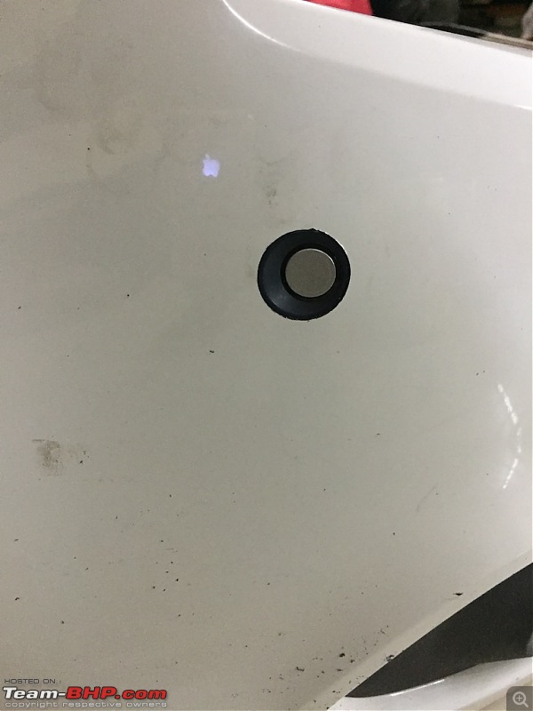
Just stick them and let it dry for some time around 2-4 hours. Just make sure its in right place and sensors stay parallel to car.
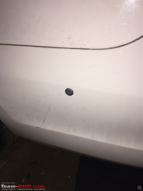
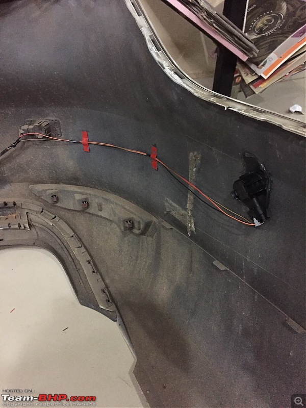
PLA - REAR BUMPER :
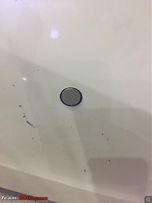
As we did in front sensor install, measure sensor size. Rear sensors are smaller so you can use drill bits to make hole.
We used drill bit which came with aftermarket rear bumper camera (haha). It matched size of rear sensor.
After drilling, use file tool to smoothen rough edges.
Using adhesive (bondtite) stick rear PLA sensor along with bracket.
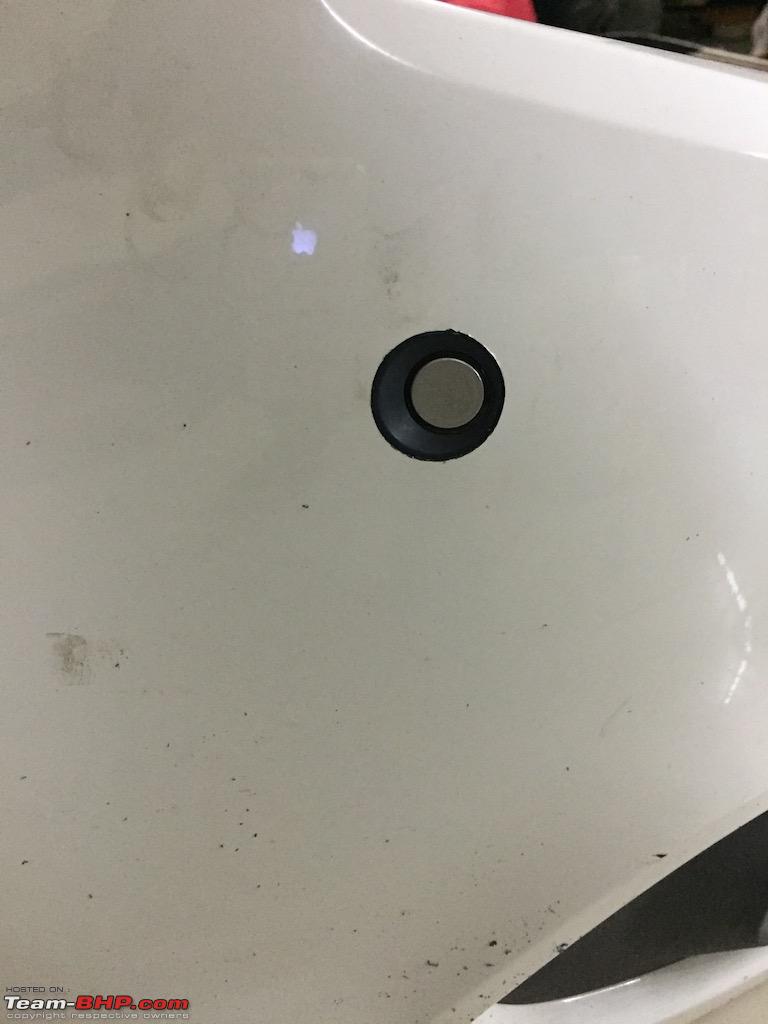
Right side PLA sensor :
Left side PLA sensor :
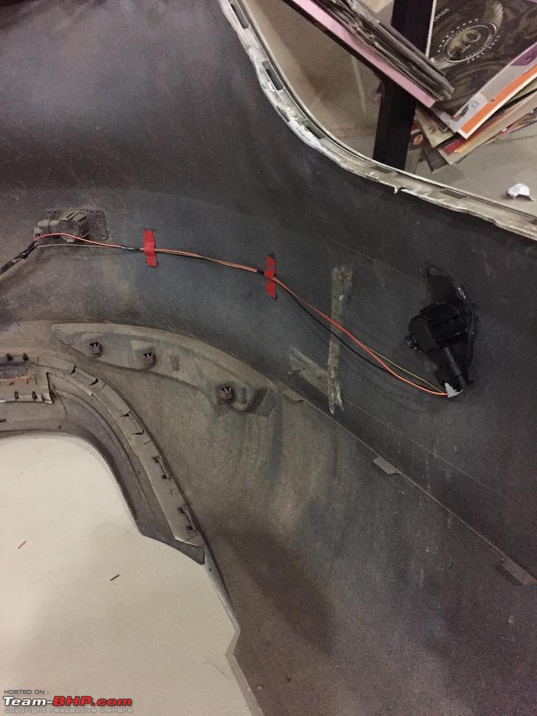
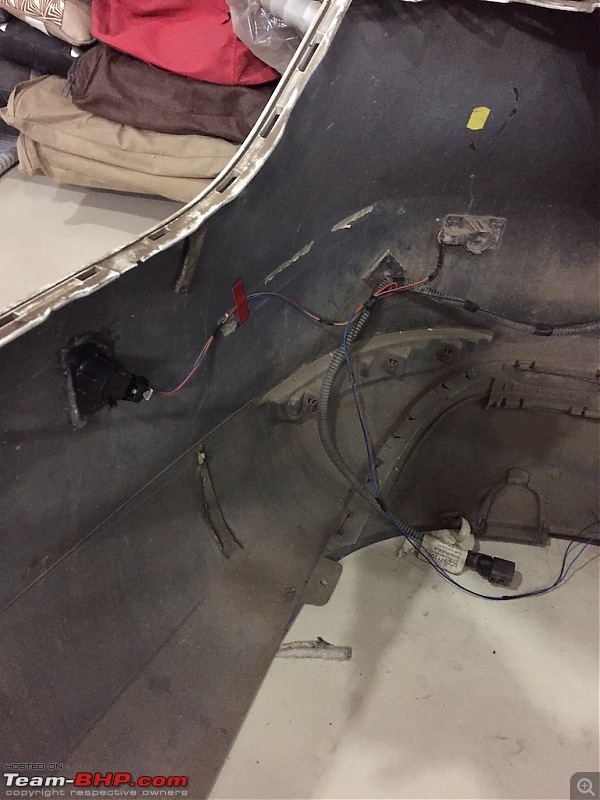
So now we have installed front and rear PLA sensors. Now we will move on to wiring installation.
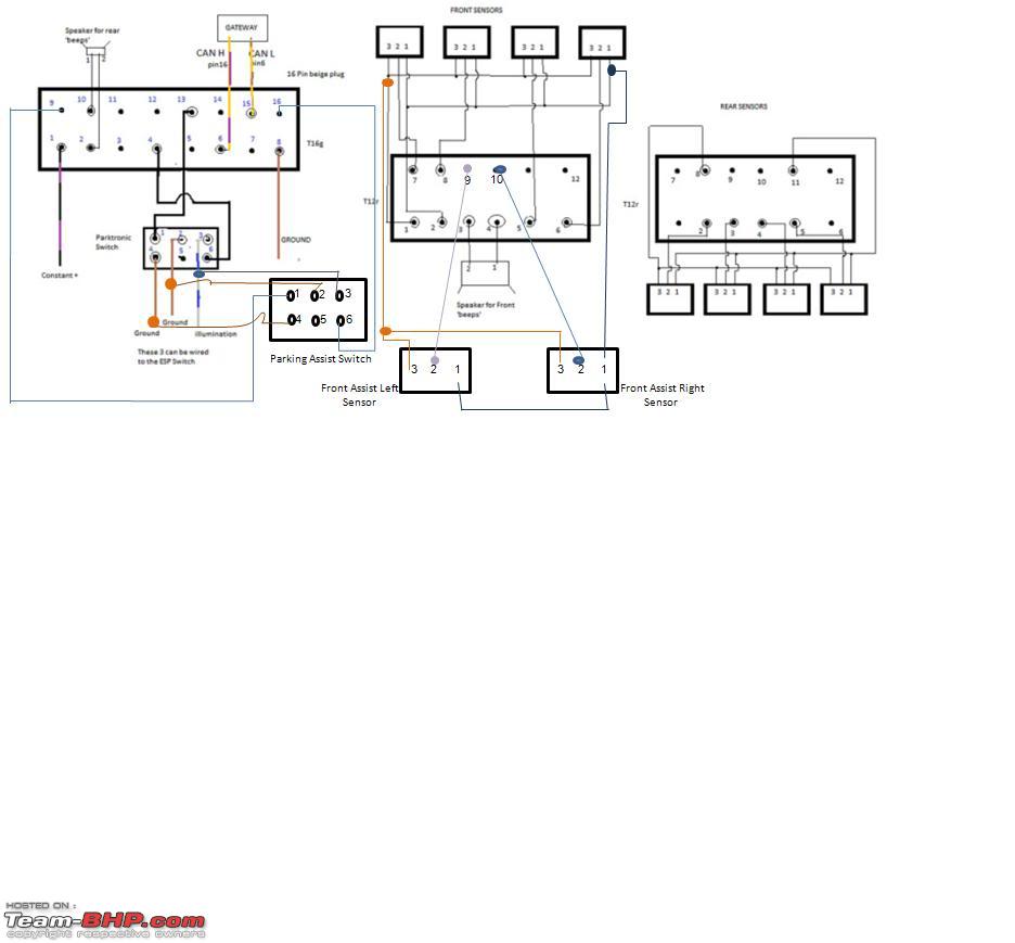
WIRING :
Now if you spare some time on this and understand diagram, then it's pretty simple. Otherwise it may confuse you. Because the diagram we used here doesn't match actual wiring diagram of PLA kit. But luckily everything works even after following incorrect diagram. phew
Seller was very helpful and he even sent wiring connections as follows.
Front bumper parking sensor cable Black T8 Plug--- Yellow T12 Plug of Parking module
T8/1---------T12/1(ground wire)
T8/2---------T12/2(firing line)
T8/3---------T12/5 Front left Green and white
T8/4---------T12/6 Middle left Green and yellow
T8/5---------T12/7 Middle Right Green and Red
T8/6---------T12/8 Front Right Green and Blue
T8/7---------T12/9 (PLA Module Left)Black and Green
T8/8---------T12/10(PLA Module Right)Grey and Green
Switch Cable
Front Parking Sensor Switch ----------Parking Module Yellow T16 Plug T6/2-------T16/13(Green and Blue)
T6/5-------T16/4(Green and While)
PLA Switch--------Parking Module Yellow T16 Plug
T6/2-------T16/9(Blue and white)
T6/5-------T16/16(Purple and white)
PLA2.0 Cable
PLA2.0 Rear Bumper Cable
White and Purple cable ---Black Plug of Parking Module T12/6(Right PLA Sensor)
Yellow and Purple cable-- Black Plug of Parking Module 12/10(Left PLA Sensor)
Red and Yellow—Positive wire of Rear Bumper sensor cable (doubling same color wire and get power supply.
brownish yellow---Negative cable of rear bumper sensor(Ground)( doubling same color wire)
We followed this diagram below. But as you can see, it is incomplete. There's no instructions for rear PLA sensor connection.
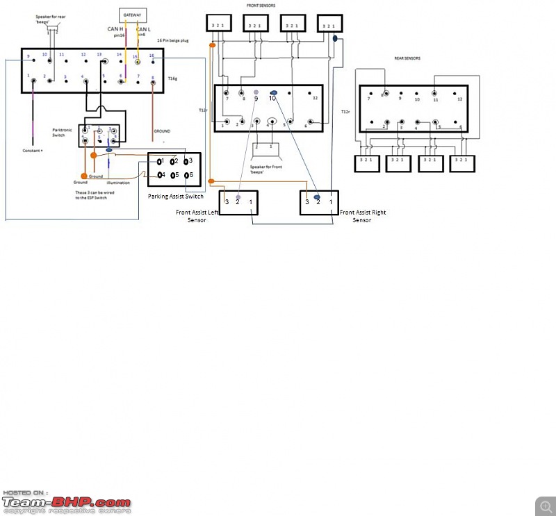
image source - vwvortex
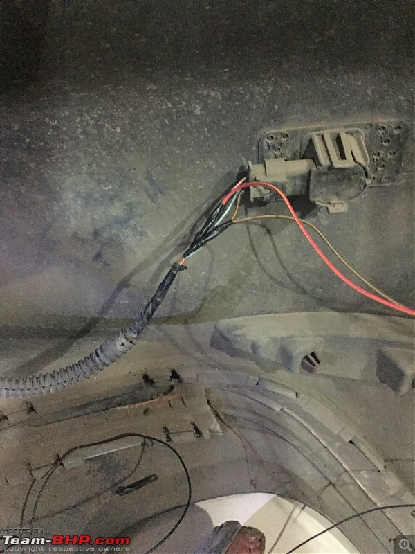
PARK ASSIST SWITCH wiring (left side connector) for PLA module :
Starting with Park Assist switch wiring. First of all get this wire beneath dashboard throughout upper right corner of dashboard, so that we can connect it to PLA module.
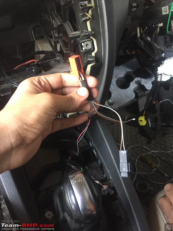
Now as you can see in the diagram, we need to tap brown(ground) and grey (illumination) wire into Park Pilot switch.
This switch comes with additional brown and grey wire connector. This can be used if you want to install TPMS (Tire Pressure Monitoring System) switch.
Now as you can see there are 2 wires coming out of switch - green and pink. Pull that cable throughout dashboard to upper right corner where PLA module is placed.

Now you need to insert 2 wires to
T16 (16 pin connector i.e left connector) :
PINK wire to
PIN 9 GREEN wire to
PIN 16 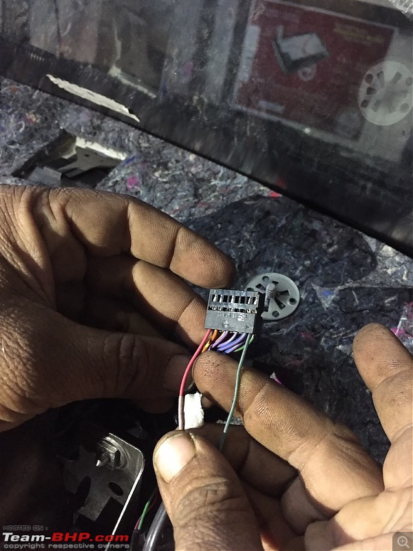
If you look closely, you can clearly see that there are marking of numbers on connector itself. Using that marking we are going to insert new wires.
So that switch wiring is completed. We will connect switch later on when we put back dashboard.
FRONT PLA SENSOR wiring (middle connector) for PLA module :
As you can see in the diagram, you just need to insert 2 wires to
T12(a) (12 pin connector i.e middle connector)
GREEN with black stripes wire to
PIN 9 GREEN with white stripes wire to
PIN 10 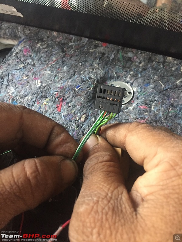
Front PLA sensor wiring is done. Now we will move on to Rear.
REAR PLA SENSOR wiring (right connector) for PLA module :
As I described earlier, if you look at the diagram there is no details given for how to connect rear PLA sensor.
So we had to check by ourselves only and finally got correct PIN numbers after several discussions.
You need to insert 2 wires to
T12(b) (12 pin connector i.e right connector)
BLUE wire to
PIN 6 BLACK wire to
PIN 10 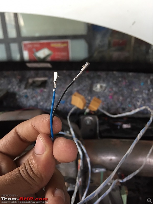
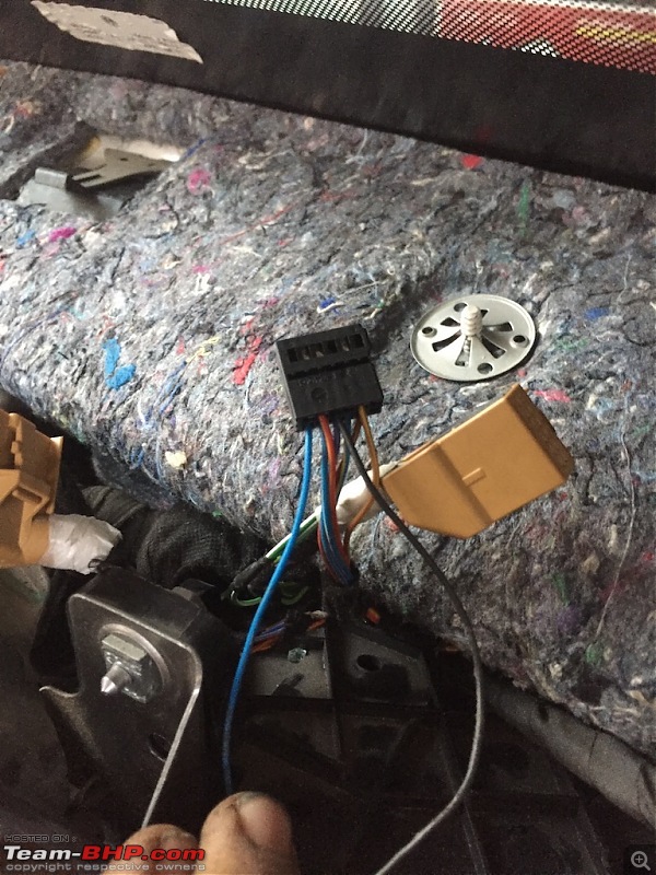
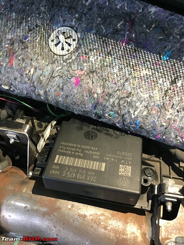
Now connect all the connectors back to PLA module and put it back in position.
Now that we are done with PLA module wiring, we will be moving on to PLA sensor connection.
FRONT PLA sensor wiring :
Now if you look at wiring diagram, it is pretty straight forward.
Each sensor consist of 3 wires.
LEFT PLA
One is for GROUND. (brown)
One is for SIGNAL. (green with black)
One is for POWER. (red)
RIGHT PLA
One is for GROUND. (brown)
One is for SIGNAL. (green with white)
One is for POWER. (red)
We need to tap GROUND & POWER to existing parking sensors as shown in diagram.
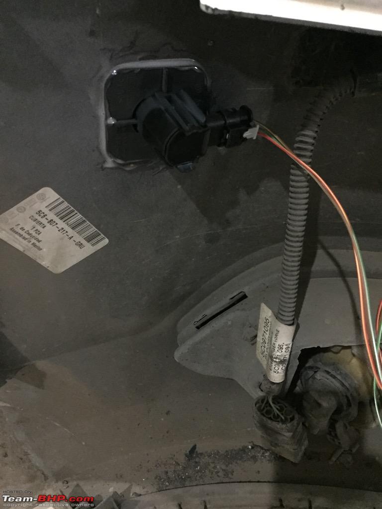
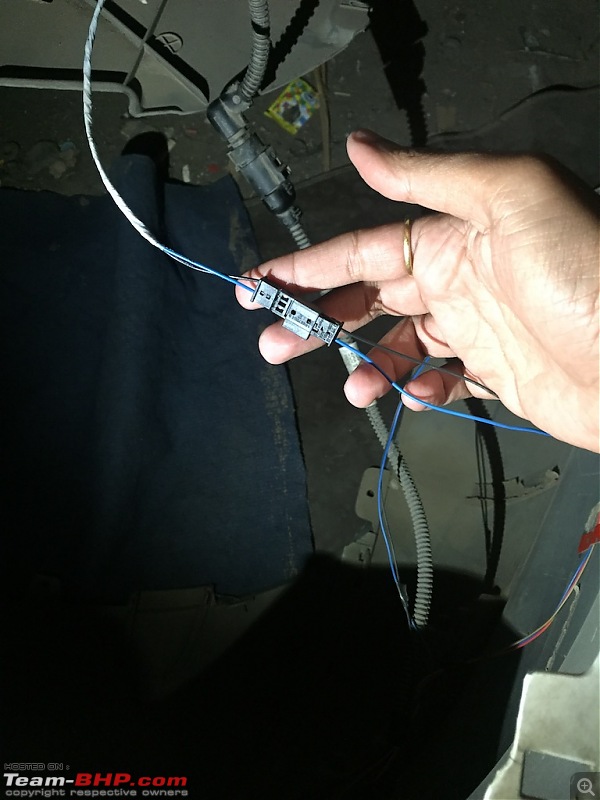
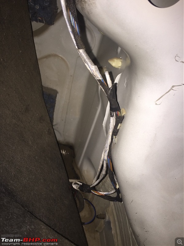
Now get 2 green wires from PLA module to front bumper from inside engine bay. You can use cloth tape for additional safety. Don't place it near any metal or engine component which gets too hot.

Now as you can see, wires are short. But you will find additional waterproof connectors which will give you enough length to cover both PLA sensors.
Connect
GREEN with white stripes to
FRONT RIGHT PLA sensor.
Connect
GREEN with black stripes to
FRONT LEFT PLA sensor.
Now moving on to rear PLA sensor.
REAR PLA sensor wiring :
Now if you look at wiring diagram, it is pretty straight forward.
Each sensor consist of 3 wires.
LEFT PLA
One is for GROUND. (brown)
One is for SIGNAL. (black)
One is for POWER. (red)
RIGHT PLA
One is for GROUND. (brown)
One is for SIGNAL. (blue)
One is for POWER. (red)
We need to tap GROUND & POWER to existing parking sensors. There is no diagram which shows this step but, it's similar to front sensor wiring so no issue.
Connect
BLUE to
REAR RIGHT PLA sensor.
Connect
BLACK to
REAR LEFT PLA sensor.
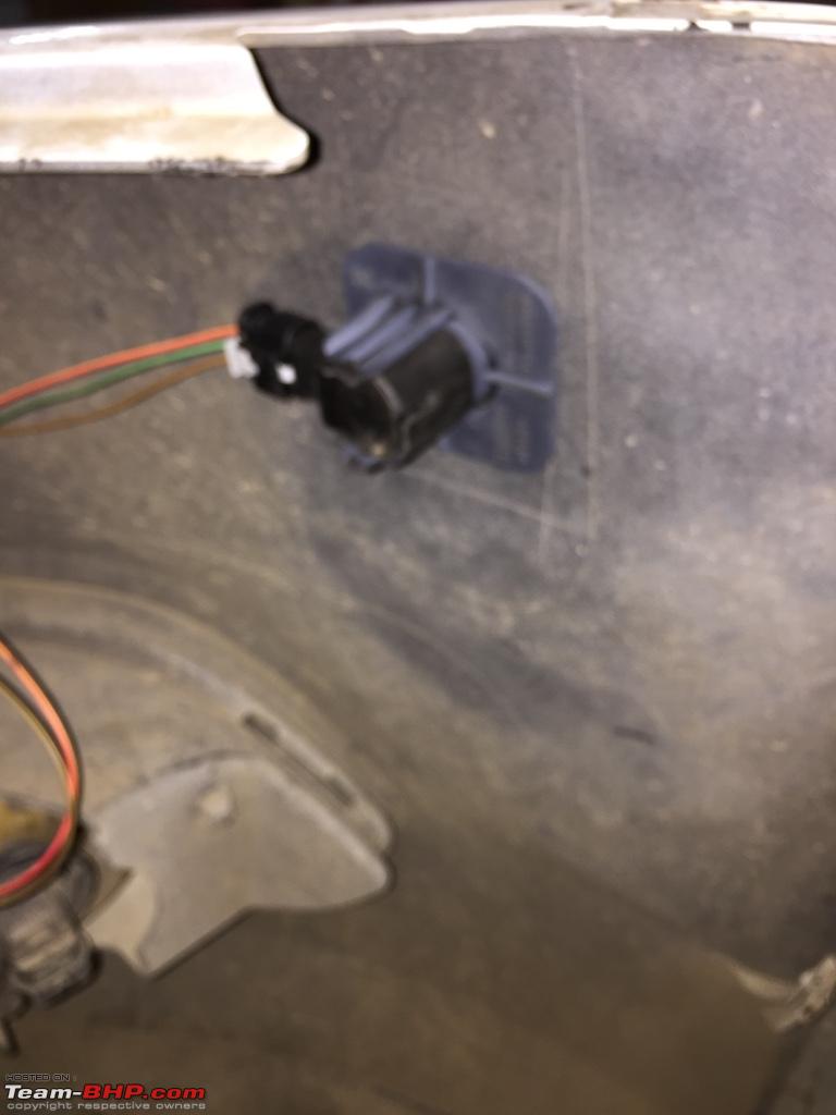
Now connect blue and black wire connector with each other and this will go from trunk to PLA module, all the way through interior panels.

Now after all this wiring instructions, you will be wondering why I chose green wire for front and black/blue for rear.
If you look closely at PLA kit, you will see that it comes with all proper connectors and proper wires. You just need to figure out which one goes where.
Green wire is short compared to blue/black so it is but obvious that blue/black will go to rear sensors.
So finally done with wiring, we will head on to coding section.
CODING :
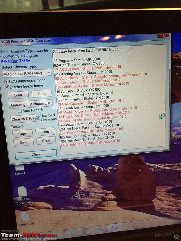
Now moving to very important step. Don't get scared after connecting VCDS to your car. You will see many fault codes.
There will be almost every warning light lit up on your instrument cluster. It's ok.
You will see so many RED (fault codes) in VCDS scan. Don't worry it's normal. It will go after proper CODING.
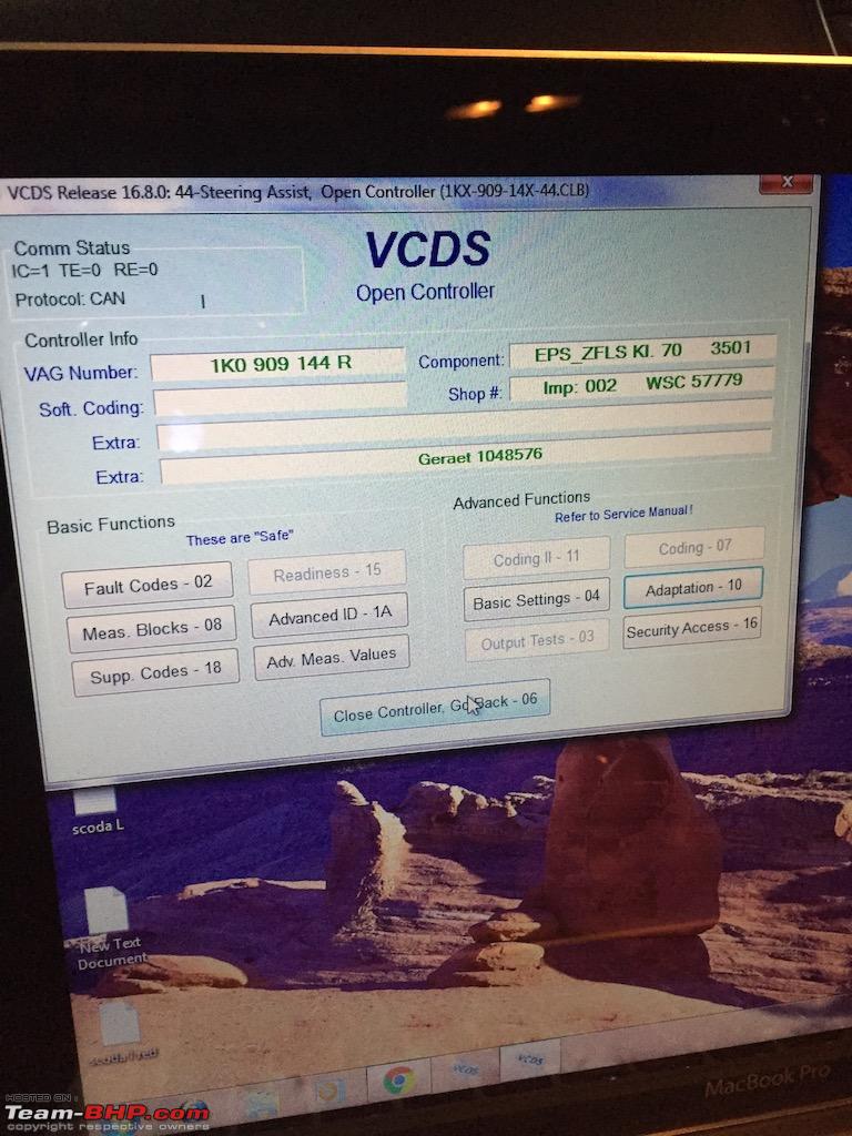
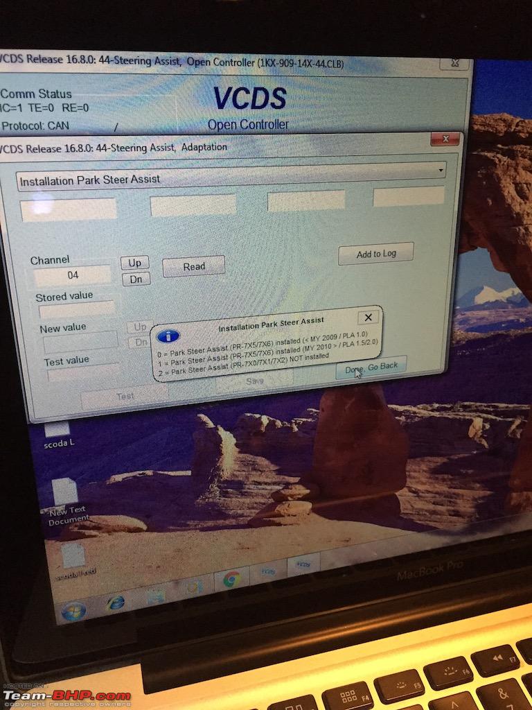
 STEERING ASSIST :
Go to
44. STEERING ASSIST under select control module.
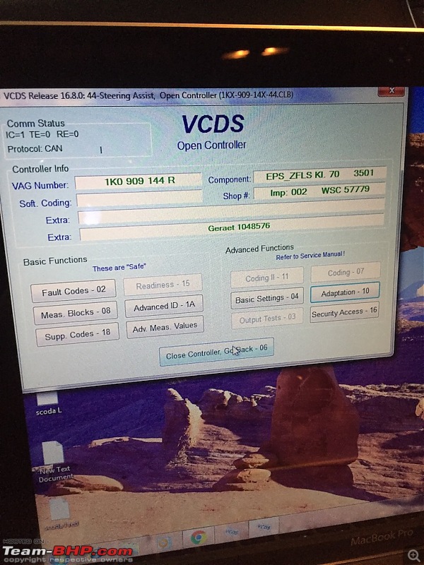
Now go to
ADAPTATION. 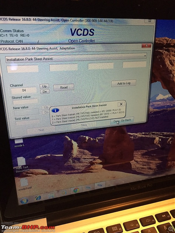
Under ADAPTATION menu, go to
INSTALLATION PARK STEER ASSIST drop down menu.
And go to
channel 4. and click on READ.
It will show you
2 as stored value.
Now put
1 as new value. Click save.
Now go back. Exit controller.
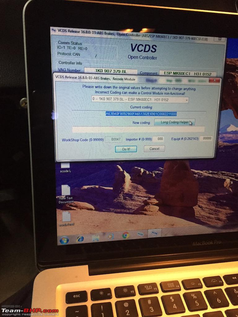
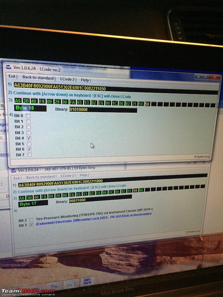
ABS CONTROLLER :
Go to
03. ABS CONTROLLER under select control module.
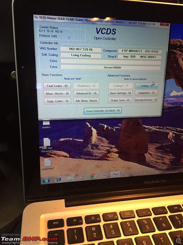
Now click on CODING.
You will see huge code. Copy it and keep it safe somewhere in case if you need it in near future.
Now click on
LONG CODING HELPER.
Now go to
Byte 17.
Check
Bit 2 if you want to install
TPMS.
Check
Bit 3 if you want to install
XDS.

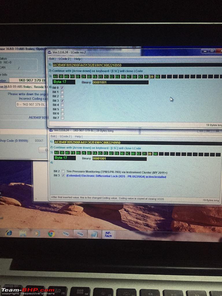
Now click on
Lcode 2.
Go to
Byte 17.
Check
Bit 0.
Check
Bit 3. 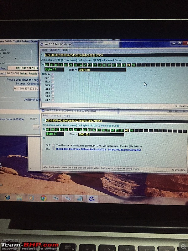
Now go to
Byte 18.
Check
Bit 4.
Check
Bit 6. 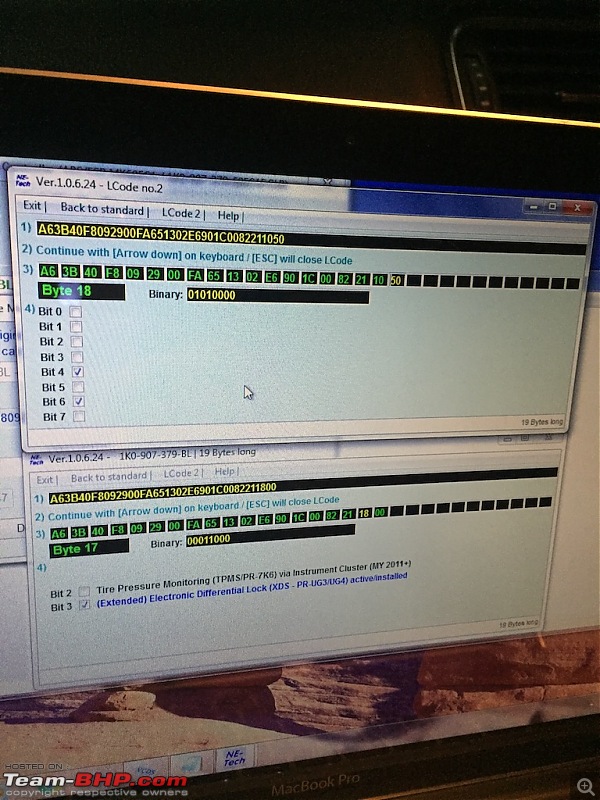
Click
Exit.
Now you will see new code.
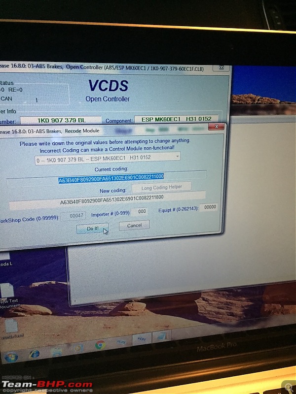
Now click
Do It. 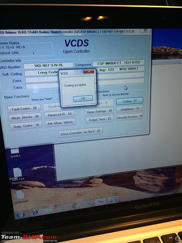
You will see
coding accepted. VOILA.
You will see that most of the fault codes have gone already. Some will be there. Don't worry we can clear them by steps below.
Now turn on car.
Rotate steering fully to the right.
Rotate steering fully to the left.
Now you will see that steering angle sensor error has gone. (ESP light will go off from instrument cluster)
Tell someone to walk around your car for Park assist calibration and 360 OPS.
Now roll up and down all the windows 2 to 3 times.
After driving for about 100 metres you will notice that all warning lights from instrument cluster has gone.
After scanning with VCDS, you will see no errors. phewwww.
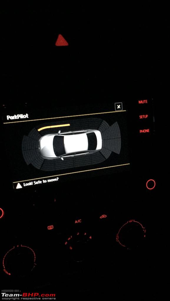
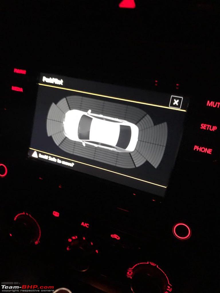
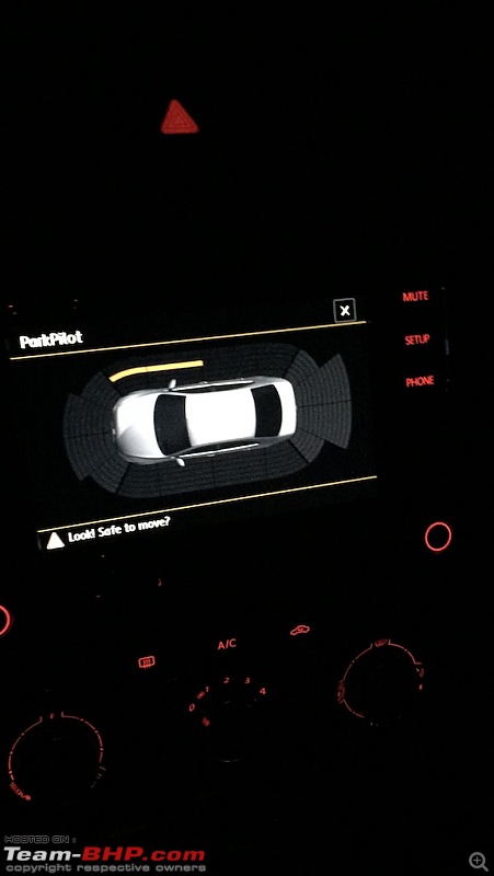
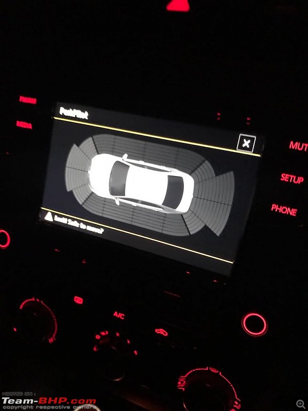
360 OPS :
It will automatically turn on after coding.
Remember it will turn on only if any object is nearby.
THANKSGIVING :
If you have done everything right then congratulations. You have successfully pulled off this difficult task. It's tiring and time taking installation, but outcome is surely delicious.
I would like to thank our local technician
Rajubhai for assembling and dismantling all the interior parts carefully.
I would also like to thank our local electrician
Shoyeb for doing all electrical job and letting us work in his shop.
I would also like to thank our tech support
Vishesh - AVS TUNING for answering all the queries regarding coding and wiring stuff.
I would also like to thank
Tanveer - Team-BHP handle for all the inputs and inspiring us to pull off this tricky mod.
I would also like to thank
GTO and all moderators for always motivating me and for providing such a huge platform for car enthusiasts. clap:
And finally I would like to thank my best friend
Mehboob Siddique for agreeing on doing this mod and obviously letting his car for this mod. :)
Good lord! That is some amazing work. Well done sir.
Wow! That's some serious DIY,
Oh god this is serious stuff. Pretty awesome. Its not a DIY its a DIYIE (Do it yourself if an expert) clap:
Does the park pilot require throttle input or is it completely automated.
Wow... This is awesome. What patience and knowledge. Respect. The other day it took me 2 hours to assemble my son's hot wheels set. And that too with some serious inputs from my 5 year old.
Thanks for sharing this amazing DIY maddyguage. It was a very difficult job, equally beautifully done. Your planning and execution is top of the mark. The detailed step by step guide with very informative and clear pictures will assist many of us in our planned DIYs.clap:
Wow, Thats passion at work :).
Attention to detail and also effort to pen down detailed instruction (which many OEM instruction manual may not have) is much appreciated.
Awesome step by step instructions. End result video too good.clap:
| All times are GMT +5.5. The time now is 21:05. | |