Team-BHP > Technical Stuff > DIY - Do it yourself
Register New Topics New Posts Top Thanked Team-BHP FAQ


Reply
  Search this Thread
5,113 views
Old 1st May 2020, 22:46   #1
BHPian
 
HimuraKenshin's Avatar
 
Join Date: Mar 2009
Location: Mumbai/London
Posts: 287
Thanked: 327 Times
HM Ambassador MPFI DIY - Ignition Amplifier

There is a certain part that goes into the ignition system of my HM ambassador knows as the ignition amplifier. Without it, the car will no start. Nowadays, it is quire difficult to procure, and where available, retailers are quoting an arm and a leg.
The original MRP was around 1900.
My car has sadly gone through 2 of these units, and i do not want to purchase another one, hence thought of reverse engineering it and making the circuit more robust.

Would like to thank fellow forum member Ilango, who has helped me with every query i had and has been an immense support. I doubt i'd have reached so far in this project without his invaluable help.

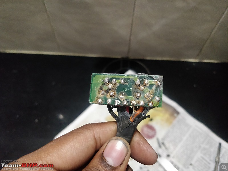
The first challenge was the fact that the unit is sealed with potting compound. The usual method of boiling in hot water and worked with little success, and i almost destroyed taking it apart. Soaking it in acetone/ mekp didn't help either.
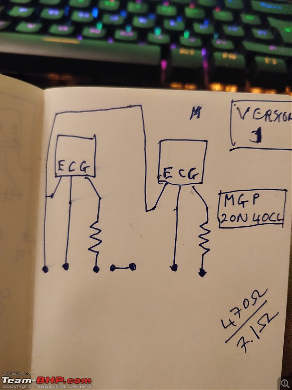
Once the circuit was out, i was able to trace it to the following diagram.
The circuit was fairly simple, with each IGBT receiving an input from the ECM and then firing the coil.

HM Ambassador MPFI DIY - Ignition Amplifier-img_20191225_154222.jpg

HM Ambassador MPFI DIY - Ignition Amplifier-img_20191225_155458.jpg

HM Ambassador MPFI DIY - Ignition Amplifier-img_20191225_160911.jpg

Since i took apart 2 units, the circuit was slightly different for the two.
They both used 2 different IGBTS, and one used re-settable fuses in the circuit as well. PFB the 2 different circuits.
Circuit 1- Using NGP8203N and the re-settable fuse MF-RX185 and a 470 ohm 1/2 watt resistor.
HM Ambassador MPFI DIY - Ignition Amplifier-version-1.jpg

Circuit 2- Using MGP20N40CL and a 470 ohm 1/2 watt resistor.
HM Ambassador MPFI DIY - Ignition Amplifier-version-2.jpg

I drew up the circuit and exported the required GERBER files for printing. post which i sent them to be etched and printed from a vendor in gujrat.
Circuit layout: Q1 and 2 are the IGBTs, RF1 and 2 are re-settable fuses, and R1 and 2 are 470 ohm 1/2 watt resistors.
HM Ambassador MPFI DIY - Ignition Amplifier-automotive-ignition-amplifier-mountiung.jpg

I need your help with thje following:

1. Since both the IGBTs are end of lifecycle components, which IGBT should i go for, which will be more robust/ reliable than the current one?
2. Should i use the re-settable fuse in the circuiut?
3. Where should i purchase the components from? Lamington road? or are there any service providers online that do this. I tried element 14, but apparently you need a GST number to order from them. I do not want to buy from ali express.

Also attached below are the data sheets of the 2 IGBTS.
MGP20N40CL_MotorolaInc.pdf
Attached Files
File Type: pdf NGP8203N_ONSemiconductor.pdf (170.5 KB, 241 views)
HimuraKenshin is offline   (11) Thanks
Old 3rd May 2020, 09:13   #2
Distinguished - BHPian
 
Join Date: Oct 2012
Location: Delhi
Posts: 8,098
Thanked: 50,831 Times
Re: HM Ambassador MPFI DIY - Ignition Amplifier

Great bit of DIY, excellent.

I really can’t help you with where to get these in India. Here in the Netherlands I would just use the internet to find a replacement and or talk to the shop in question and ask them for advice. I just don’t know enough about these components, so I will need to trust somebody else judgement.

I am wondering why you have already gone through two of these? Is this a known common problem? If not, it is very likely there is another problem. e.g. damaged wire loom, or something.

Normally these are extremely reliable components I would think.

Good luck, keep us posted how you get on!

Jeren
Jeroen is online now   (1) Thanks
Old 3rd May 2020, 10:10   #3
Distinguished - BHPian
 
R2D2's Avatar
 
Join Date: Oct 2008
Location: Pune
Posts: 3,231
Thanked: 5,742 Times
Re: HM Ambassador MPFI DIY - Ignition Amplifier

Quote:
Originally Posted by HimuraKenshin View Post
There is a certain part that goes into the ignition system of my HM ambassador knows as the ignition amplifier. Without it, the car will no start. Nowadays, it is quire difficult to procure, and where available, retailers are quoting an arm and a leg. The original MRP was around 1900. My car has sadly gone through 2 of these units, and i do not want to purchase another one, hence thought of reverse engineering it and making the circuit more robust.
Very interesting DIY. Have you tried Mouser for the IGBTs? They deliver to India in fact they have an office in Bangalore I believe.

Was the failure caused due to heat and or corrosion? That PCB looks corroded. Do these IGBTs need heat sinks and more robust sealing from heat dust and moisture using a silicone compound for e.g.?

Last edited by R2D2 : 3rd May 2020 at 10:16.
R2D2 is offline   (1) Thanks
Old 3rd May 2020, 15:49   #4
BHPian
 
HimuraKenshin's Avatar
 
Join Date: Mar 2009
Location: Mumbai/London
Posts: 287
Thanked: 327 Times
Re: HM Ambassador MPFI DIY - Ignition Amplifier

Quote:
Originally Posted by Jeroen View Post
Great bit of DIY, excellent.


I am wondering why you have already gone through two of these? Is this a known common problem? If not, it is very likely there is another problem. e.g. damaged wire loom, or something.

Normally these are extremely reliable components I would think.

Good luck, keep us posted how you get on!

Jeren
My ignition coil was failing when hot, and hence i suspect that caused the previous 2 modules to fail. I hence changed that as well
HimuraKenshin is offline  
Old 3rd May 2020, 19:23   #5
Senior - BHPian
 
Join Date: Jul 2009
Location: Calcutta
Posts: 4,668
Thanked: 6,217 Times
Re: HM Ambassador MPFI DIY - Ignition Amplifier

Quote:
Originally Posted by Jeroen View Post

Normally these are extremely reliable components I would think.
Quote:
Originally Posted by HimuraKenshin View Post
My ignition coil was failing when hot, and hence i suspect that caused the previous 2 modules to fail. I hence changed that as well
I think you are on the right track.

Had both a Contessa and a couple of Ambys, one of them a MPFI. The Contessa was carb. Don't remember its ignition system. Because it never gave trouble. No trouble from the MPFIs ign system also. So no need to reengineer the ign system.

Source your ign coils properly. Check your alternator voltage.

The IGBTs - fail open, fail short?

Regards
Sutripta
Sutripta is offline  
Old 4th May 2020, 14:21   #6
Distinguished - BHPian
 
Join Date: Oct 2012
Location: Delhi
Posts: 8,098
Thanked: 50,831 Times
Re: HM Ambassador MPFI DIY - Ignition Amplifier

Quote:
Originally Posted by HimuraKenshin View Post
My ignition coil was failing when hot, and hence i suspect that caused the previous 2 modules to fail. I hence changed that as well
The most common reason for ignition coils failing tends to be problems with your spark cables and or the common cable between coil and distributor.

A bad spark plug ignition cable will have a much higher than normal resistance. This high resistance causes a very high amount of voltage to be generated from your ignition coil's secondary winding. This excessive voltage creates a high amount of heat which consequently melts the coil's wire insulation.

You better check your spark cables as well. Check for corrosion on both ends and check the resistance with an ohm meter.

Conversely, if your sparks are in a bad shape, or not properly gapped, again the coil might get damaged. Even the timing (pre-ignition) and fuel mixture does have an effect on how much voltage is on the cables and thus coming from the coil.

I would definitely check all of the above, if you haven’t already. I don’t understand coils and the ignition amplifier failing this much, unless it is just a poor design and or poor quality products.

Good luck, lets us know how you get on. Very interested to see your final more robust version!

Jeroen
Jeroen is online now  
Old 4th May 2020, 15:12   #7
BHPian
 
Join Date: Dec 2005
Location: bang
Posts: 878
Thanked: 3,117 Times
Re: HM Ambassador MPFI DIY - Ignition Amplifier

i normally don't comment on car DIY since i am a total noob in that area, but this concerns industrial electronics and i am known to fiddle around with them. IGBT's generally have much higher current carrying/switching capacities and are used extensively by indian railways for all their motor drive chopper circuits and also for their headlight UPS circuits. If you know someone from railway electronic dept they can easily point out the source to you. i am assuming that this part is an OEM from HM.

One tip: Ground the emitter of the IGBT's independently and avoid loops.
srini1785 is offline   (1) Thanks
Old 6th May 2020, 16:55   #8
Team-BHP Support
 
Jaggu's Avatar
 
Join Date: May 2004
Location: Bangalore
Posts: 20,215
Thanked: 15,906 Times
Re: HM Ambassador MPFI DIY - Ignition Amplifier

Very interesting, this question is for Electronics engineers out there. Keenly watching the thread for progress. Wishing you the best.
Jaggu is offline  
Old 6th May 2020, 19:44   #9
BHPian
 
Join Date: Apr 2013
Location: Detroit,MI/UP70
Posts: 27
Thanked: 29 Times
Re: HM Ambassador MPFI DIY - Ignition Amplifier

Quote:
Originally Posted by HimuraKenshin View Post

I need your help with thje following:

1. Since both the IGBTs are end of lifecycle components, which IGBT should i go for, which will be more robust/ reliable than the current one?
2. Should i use the re-settable fuse in the circuiut?
3. Where should i purchase the components from? Lamington road? or are there any service providers online that do this. I tried element 14, but apparently you need a GST number to order from them. I do not want to buy from ali express.
Man! you have put some great effort tracking down the components and drawing the PCB. Since you have drawn the PCB yourself I suggest widening the IGBT Collector and Emitter traces. It appears from the layout that they are approx equal to the pad hole diameter which for TO-220 is around 40-50 mils. This will make the PCB much more rugged.

1 & 3. For the IGBT, use any Ignition IGBT with a >400 V and >20 A rating. If you use a TO-220 package, please mount it on a heatsink (precut available everywhere for peanuts) to make sure that it can withstand higher operating and ambient temperatures. You can find for the components on digikey.com and mouser.com. Shipping to India might take some time because of the COVID though.

2. Please use the resettable fuse. It is for the IGBT protection from thermal, over current and over voltage.

Wishing you good luck for a successful DIY
rachitagarwal is offline   (1) Thanks
Old 8th May 2020, 22:26   #10
BHPian
 
HimuraKenshin's Avatar
 
Join Date: Mar 2009
Location: Mumbai/London
Posts: 287
Thanked: 327 Times
Re: HM Ambassador MPFI DIY - Ignition Amplifier

Quote:
Originally Posted by rachitagarwal View Post

1 & 3. For the IGBT, use any Ignition IGBT with a >400 V and >20 A rating. If you use a TO-220 package, please mount it on a heatsink (precut available everywhere for peanuts) to make sure that it can withstand higher operating and ambient temperatures. You can find for the components on digikey.com and mouser.com. Shipping to India might take some time because of the COVID though.

2. Please use the resettable fuse. It is for the IGBT protection from thermal, over current and over voltage.

Wishing you good luck for a successful DIY
Hi! thanks for your reply!
Could you help me pick between the two: (Both are my ON/Fairchild)

FGP3040G2-F085
ISL9V5036P3-F085

If there is some other IGBT you can recommended, that would be great a well.
There is also a NPN power Darlington transistor numbered "BU931T" can this be used? (datasheet attached)

Also, should i use a 1.85 A or 2.5A resettable fuse? The one originally was 1.85

thanks,
Shom
Attached Files
File Type: pdf BU931T.pdf (656.9 KB, 175 views)
HimuraKenshin is offline  
Old 13th May 2020, 11:50   #11
BHPian
 
Join Date: Dec 2005
Location: bang
Posts: 878
Thanked: 3,117 Times
Re: HM Ambassador MPFI DIY - Ignition Amplifier

Quote:
Originally Posted by HimuraKenshin View Post
There is also a NPN power Darlington transistor numbered "BU931T" can this be used? (datasheet attached)
For using an NPN transistor, you need to connect the coils to the emitter and collector to 12v. It depends on how your car is wired. Most wiring circuits that i have seen, ground the negative of the battery which means you can only switch PNP. The circuit that you have shown is also for PNP switching.
srini1785 is offline   (1) Thanks
Old 8th September 2020, 10:40   #12
BHPian
 
HimuraKenshin's Avatar
 
Join Date: Mar 2009
Location: Mumbai/London
Posts: 287
Thanked: 327 Times
Re: HM Ambassador MPFI DIY - Ignition Amplifier

So I've successfully made the prototype.
I've used the ON Semiconductor - ISL9V5036P3- IGBT which has a much higher rating compared to the stock one supplied with the car.
Other components such as the resistors and re-settable fuses have been beefed up as well.
I would like to immensely thank Ilango, which im sure most of you guys know, for helping me and answering all my silly questions
Pics and video as below:


Last edited by HimuraKenshin : 8th September 2020 at 10:47.
HimuraKenshin is offline   (2) Thanks
Old 12th September 2020, 19:48   #13
Senior - BHPian
 
Join Date: Jul 2009
Location: Calcutta
Posts: 4,668
Thanked: 6,217 Times
Re: HM Ambassador MPFI DIY - Ignition Amplifier

Car under lockdown for last few months?

Sutripta
Sutripta is offline  
Old 12th September 2020, 20:47   #14
BHPian
 
HimuraKenshin's Avatar
 
Join Date: Mar 2009
Location: Mumbai/London
Posts: 287
Thanked: 327 Times
Re: HM Ambassador MPFI DIY - Ignition Amplifier

Quote:
Originally Posted by Sutripta View Post
Car under lockdown for last few months?

Sutripta

Indeed! just driving it around for grocery errands.
HimuraKenshin is offline  
Reply

Most Viewed


Copyright ©2000 - 2024, Team-BHP.com
Proudly powered by E2E Networks