Team-BHP > Technical Stuff > DIY - Do it yourself
Register New Topics New Posts Top Thanked Team-BHP FAQ


Reply
  Search this Thread
83,882 views
Old 17th July 2020, 21:36   #16
Senior - BHPian
 
Join Date: Jul 2009
Location: Calcutta
Posts: 4,668
Thanked: 6,217 Times
re: DIY: Metal model engine building UPDATE: build complete (page 16)!

The dimensions mean that the bearing is 6000.
The component layout makes me think that you'll have to slide the shaft through for 2/3 of its length through one of the bearings - a thumb push fit. Which is not ideal. I would have suggested 10 mm silver steel rod (these are ground), but fit in bearing is likely to be tighter. Check.

The bearing pedestals are likely to be difficult to machine. The bore is not through. and height of centre above base has to be the same for both. And considering the pedestal castings are part of the kit, you don't get do overs. Your advantage is that it only has to run for a few minutes over its entire life!

One gets honed seamless tubes. But in such miniscule quantities, I don't know.

I would start work from the crank/ flywheel end.

Sutripta
Sutripta is offline   (2) Thanks
Old 18th July 2020, 00:28   #17
Distinguished - BHPian
 
Join Date: Oct 2012
Location: Delhi
Posts: 8,092
Thanked: 50,777 Times
re: DIY: Metal model engine building UPDATE: build complete (page 16)!

Quote:
Originally Posted by Thad E Ginathom View Post
How is buying from China for you these days? From India it has become impossible as they can no longer effectively use ordinary post, so AliExpress is off our screens
I don’t buy anything myself directly from China. I have bought a few things on AliExpress in the past. The problem is it takes weeks, if not months to arrive.

As I mentioned, stores like HBM get most of their stock from China, on a continuous basis. But they have been suffering and are still not up to normal stock levels.

Quote:
Originally Posted by Sutripta View Post
The dimensions mean that the bearing is 6000.
Thanks. How do you go from dimension to a number? Is there some sort of table. What about the type of bearing, e.g. axial/radial/sealing etc. Again, I want something that has the least resistance possible

Quote:
Originally Posted by Sutripta View Post
The component layout makes me think that you'll have to slide the shaft through for 2/3 of its length through one of the bearings - a thumb push fit. Which is not ideal. I would have suggested 10 mm silver steel rod (these are ground), but fit in bearing is likely to be tighter. Check.
yes, I have steel, but silver steel is most likely better.

Quote:
Originally Posted by Sutripta View Post
One gets honed seamless tubes. But in such miniscule quantities, I don't know.
Henry had an address, I havent checked them yet. I want to try the boring first.

When it comes to production: We have lift off!

I started tonight in earnest on a couple of things:

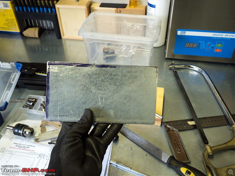
First thing the base plate. I had a piece that was almost the correct size. It is 5mm short, but that is alright. Just had to tighten it up a bit, was a bit rough;. No fancy machinery required. Just a vice, a file and some good old elbow grease

DIY: Metal model engine building UPDATE: build complete (page 16)!-p7170001.jpg

DIY: Metal model engine building UPDATE: build complete (page 16)!-p7170003.jpg

DIY: Metal model engine building UPDATE: build complete (page 16)!-p7170004.jpg

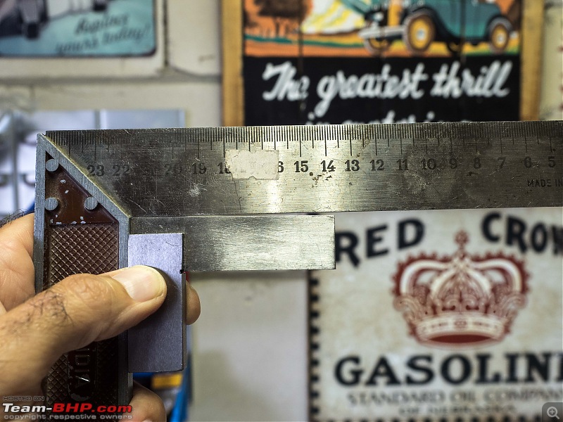
I also discovered a problem with one of my tools. this thing is not at a 90o Angle at all! I did some checking, because I bought this a few months ago and everything else I have is several decades old. But it is indeed the new tool that is buggered!

DIY: Metal model engine building UPDATE: build complete (page 16)!-p7170002.jpg

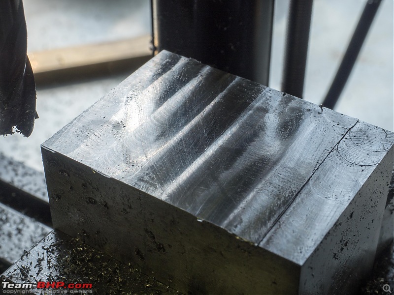
I also started machining the aluminium support for the cilinder. First thing is to bring it to the correct length. I used my mini mill. I am not satisfied with the finish at all. I used different bits (10 and 8 mm), different speeds, left-right, top bottom. But I still end up with a distinct overlap edge of each pass of the cutter.

It’s not much. Afterwards rubbing it on 1200 grid sandpaper caught rid of it quickly, but still.

Not sure what the problem is? any thoughts?

DIY: Metal model engine building UPDATE: build complete (page 16)!-p7170005.jpg

Jeroen

Last edited by Jeroen : 18th July 2020 at 00:29.
Jeroen is online now   (3) Thanks
Old 18th July 2020, 01:24   #18
Distinguished - BHPian
 
Thad E Ginathom's Avatar
 
Join Date: Jun 2007
Location: Chennai
Posts: 10,998
Thanked: 26,415 Times
re: DIY: Metal model engine building UPDATE: build complete (page 16)!

Condolences for the square that isn't. It's a good thing you soon found it out!
Thad E Ginathom is offline  
Old 18th July 2020, 09:53   #19
Senior - BHPian
 
Join Date: Jul 2009
Location: Calcutta
Posts: 4,668
Thanked: 6,217 Times
re: DIY: Metal model engine building UPDATE: build complete (page 16)!

Quote:
Originally Posted by Jeroen View Post
Thanks. How do you go from dimension to a number? Is there some sort of table. What about the type of bearing, e.g. axial/radial/sealing etc. Again, I want something that has the least resistance possible
Pretty standard single row deep groove light duty (60xx) ball bearing. Check shaft dia, then housing dia, then catalogue.
Here both the bearing and the shaft are floating. Not good, but OK I guess for what is essentially a (working) display model.

Quote:
No fancy machinery required. Just a vice, a file and some good old elbow grease
Filing accurately takes a lot of skill!

Quote:
I also discovered a problem with one of my tools. this thing is not at a 90o Angle at all!
This I cannot overemphasise - for measurement, layout and marking tools get the best you can afford. In these items the world is awash with junk now. If you go through any of the catalogues you'll find a very wide price difference of seemingly identical items. Ask yourself why. Not everything can be accounted for by 'brand tax', price gouging, or country of manufacture.

Quote:
I also started machining the aluminium support for the cilinder. First thing is to bring it to the correct length. I used my mini mill. I am not satisfied with the finish at all. I used different bits (10 and 8 mm), different speeds, left-right, top bottom. But I still end up with a distinct overlap edge of each pass of the cutter.

It’s not much. Afterwards rubbing it on 1200 grid sandpaper caught rid of it quickly, but still.

Not sure what the problem is? any thoughts?
Two things
The milling head is not trammed (squared) properly wrt the bed. Don't know if it is adjustable in your case.

Also start and end outside the workpiece.

Sutripta

Last edited by Sutripta : 18th July 2020 at 10:21.
Sutripta is offline   (1) Thanks
Old 18th July 2020, 10:12   #20
Distinguished - BHPian
 
Join Date: Oct 2012
Location: Delhi
Posts: 8,092
Thanked: 50,777 Times
re: DIY: Metal model engine building UPDATE: build complete (page 16)!

Quote:
Originally Posted by Sutripta View Post
Two things
The milling head is not trammed (squared) properly wrt the bed. Don't know if it is adjustable in your case.

Also start and end outside the workpiece.
Thanks. I am not sure about the trimmed. Because I tried going left-right, right-left, and up-down, down up. I.e. moving the bed along any direction gives the exact same result. I would think if the head is not aligned properly it would give different results in cuts perpendicular to one another?

I am going to check out a few things on my mill

Jeroen
Jeroen is online now  
Old 18th July 2020, 10:16   #21
Senior - BHPian
 
Join Date: Jul 2009
Location: Calcutta
Posts: 4,668
Thanked: 6,217 Times
re: DIY: Metal model engine building UPDATE: build complete (page 16)!

Tram, not trim.


The videos are for turret mills because the head is adjustable. Even if you can't adjust the head, it should be checked for squareness.


Sutripta

Last edited by Sutripta : 18th July 2020 at 10:19.
Sutripta is offline   (2) Thanks
Old 18th July 2020, 15:48   #22
Distinguished - BHPian
 
Thad E Ginathom's Avatar
 
Join Date: Jun 2007
Location: Chennai
Posts: 10,998
Thanked: 26,415 Times
re: DIY: Metal model engine building UPDATE: build complete (page 16)!

Quote:
Originally Posted by Sutripta View Post
This I cannot overemphasise - for measurement, layout and marking tools get the best you can afford. In these items the world is awash with junk now. If you go through any of the catalogues you'll find a very wide price difference of seemingly identical items. Ask yourself why. Not everything can be accounted for by 'brand tax', price gouging, or country of manufacture.
I bet my 4-inch Moore & Wright square, which I have had for three or four decades, is, like Jeroen's old one, also 'perfectly' (within it's tolerances: it might be a shop-floor tool, not an inspection-room tool) square. I see current price on amazon.co.uk is about 27 GBP. A 12-inch one is over 80 GBP! I guess Moore & Wright were (well, still exists) the British Starrett
Quote:
Filing accurately takes a lot of skill!
Most of the youtube machinists, even the pros, are pretty rough and ready with filing technique, but hey, the get the job done better than I would. An exception is Stefan Gotteswinter: snippets of him filing make me wish he would make a whole video about it. Jewellery: yes, I've done some neat filing. Lines that have to meet for soldering have to be straight and square --- but it isn't engineering tolerances.

I knew a silversmith. His workshop was, for a while, on my way home from work and I would drop in and chat and watch. His technique with tools was waaay off from 'textbook,' but he was still a master of his trade and his work showed it.

Last edited by Thad E Ginathom : 18th July 2020 at 15:51.
Thad E Ginathom is offline  
Old 18th July 2020, 20:44   #23
Senior - BHPian
 
Join Date: Jul 2009
Location: Calcutta
Posts: 4,668
Thanked: 6,217 Times
re: DIY: Metal model engine building UPDATE: build complete (page 16)!

Quote:
Originally Posted by Thad E Ginathom View Post
I bet my 4-inch Moore & Wright square, which I have had for three or four decades, is, like Jeroen's old one, also 'perfectly' (within it's tolerances: it might be a shop-floor tool, not an inspection-room tool) square. I see current price on amazon.co.uk is about 27 GBP. A 12-inch one is over 80 GBP! I guess Moore & Wright were (well, still exists) the British Starrett
Quote:
Originally Posted by Sutripta View Post
Mitutoyo. Absolutely standard shop equipment*. Can't go wrong with it. As is say Starrett or Moore and Wright. Steer clear of the catalogue junk.
Never had the pleasure of using one, but Browne and Sharpe is considered by many to be a grade higher than Mitutoyo, Starrett, Moore & Wright.

Sutripta
Sutripta is offline   (2) Thanks
Old 19th July 2020, 01:08   #24
Distinguished - BHPian
 
Join Date: Oct 2012
Location: Delhi
Posts: 8,092
Thanked: 50,777 Times
re: DIY: Metal model engine building UPDATE: build complete (page 16)!

Thanks for the advise!

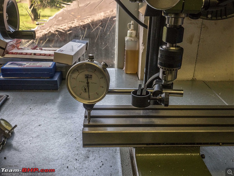
First thing I did this morning is to check some more video’s from Blondihacks on tramming and squaring.

So I checked mine:

DIY: Metal model engine building UPDATE: build complete (page 16)!-p7180001.jpg

I don’t have parallels. Would you believe HBM has been sold out for weeks/months! So I make do.

DIY: Metal model engine building UPDATE: build complete (page 16)!-p7180003.jpg

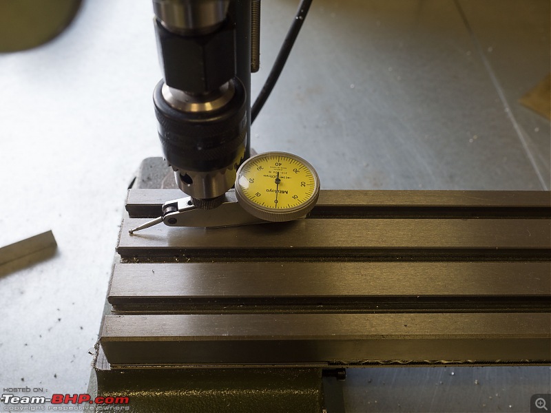
Bit of improvisation to get my dial gauge installed, but it worked. I will make a proper attachment for it too.

DIY: Metal model engine building UPDATE: build complete (page 16)!-p7180004.jpg

DIY: Metal model engine building UPDATE: build complete (page 16)!-p7180005.jpg

There was quite a bit of adjustment to be done. The only adjustment I can do on my mill is this very one. Took me a couple of hours. As you tighten the various bolts, everything moves again. But I got it set up very precisely in the end:

It is very difficult to capture these cuts properly. It looks a whole lot better, but it also feels a whole lot better! it shows more, but you can hardly feel that little ledge. Blondihack calls these water chutes.

Tried first time on a piece of spare stock

DIY: Metal model engine building UPDATE: build complete (page 16)!-p7180007.jpg

DIY: Metal model engine building UPDATE: build complete (page 16)!-p7180008.jpg

DIY: Metal model engine building UPDATE: build complete (page 16)!-p7180009.jpg

Next took, redid my cylinder support. Again, difficult to show on the photographs, but the look and feel improved considerable over what happened yesterday.

DIY: Metal model engine building UPDATE: build complete (page 16)!-p7180010.jpg

DIY: Metal model engine building UPDATE: build complete (page 16)!-p7180011.jpg

There is still some difference cutting along the X-axe versus the Y-axe. The Y is better, noticeably so.

DIY: Metal model engine building UPDATE: build complete (page 16)!-p7180014.jpg

DIY: Metal model engine building UPDATE: build complete (page 16)!-p7180015.jpg

I also experimented with cutting direction, conventional and climb milling:


I could not find any difference really. I can’t do very deep cuts anyway.

Popped over to HBM to exchange the square. They are always very accommodating, did not have the receipt. Problem is they did not have the 50 or the 75mm anymore. So for now I got myself this one:

DIY: Metal model engine building UPDATE: build complete (page 16)!-p7180016.jpg

DIY: Metal model engine building UPDATE: build complete (page 16)!-p7180017.jpg

Also, got myself some more 10mm bits. Just to see if it would make a difference.
Proxxon has its own system with metric collets. Largest one is 10mm.

DIY: Metal model engine building UPDATE: build complete (page 16)!-p7180018.jpg

Found this one, and although it is really supposed to be fastened differently I figured it would do fine in my collet too, which it did. And it made a considerable difference too!

DIY: Metal model engine building UPDATE: build complete (page 16)!-p7180019.jpg

DIY: Metal model engine building UPDATE: build complete (page 16)!-p7180020.jpg

DIY: Metal model engine building UPDATE: build complete (page 16)!-p7180021.jpg

The finish is getting better and better. Still cuts in the Y direction leave a better finish than in the X-direction. There are no adjustments on my mill as far as I can tell. I have mailed to the Proxxon service department in Germany, showing them some of these photographs. Lets see what they say.

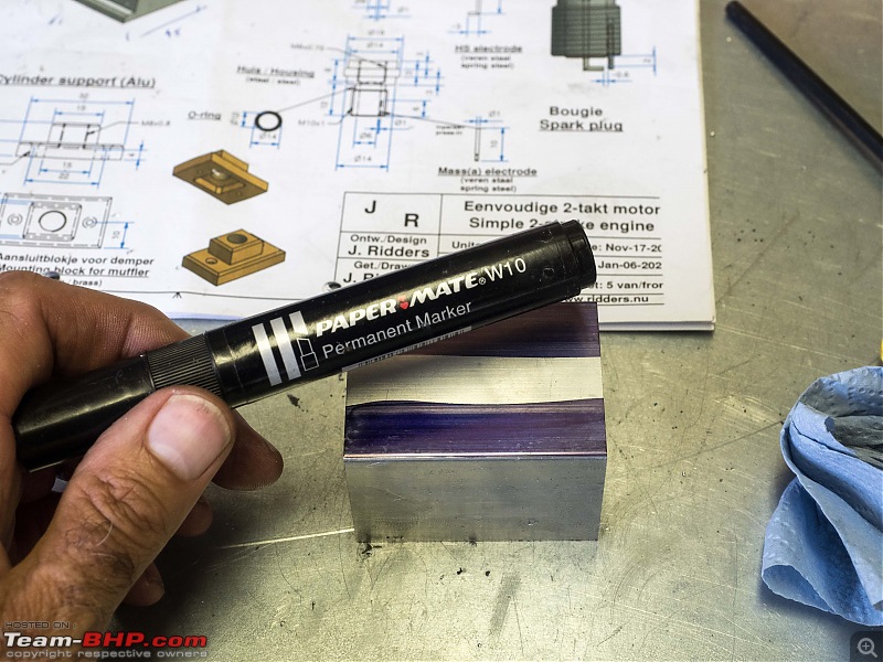
I am getting good enough finish to keep going, so I started the second cut on the cilinder support. Careful measuring and marking. I use one of these marker as marking dye. Works really well!

DIY: Metal model engine building UPDATE: build complete (page 16)!-p7180023.jpg

Almost half way into this cut. Done for the day!

DIY: Metal model engine building UPDATE: build complete (page 16)!-p7180024.jpg

DIY: Metal model engine building UPDATE: build complete (page 16)!-p7180025.jpg

DIY: Metal model engine building UPDATE: build complete (page 16)!-p7180026.jpg

i hope Proxxon comes back with some suggestion. This mill has a head that can be swung, but that is the only adjustment that can be made. I studied the drawings of the mill as well, but I can’t see anything else. So lets see.

The lady who runs the modelbuild shop where I ordered most of the materials, called this afternoon. She has almost everything ready to be shipped! So I should have it this coming week.


Jeroen

Last edited by Jeroen : 19th July 2020 at 01:23.
Jeroen is online now   (5) Thanks
Old 19th July 2020, 05:13   #25
Distinguished - BHPian
 
Thad E Ginathom's Avatar
 
Join Date: Jun 2007
Location: Chennai
Posts: 10,998
Thanked: 26,415 Times
re: DIY: Metal model engine building UPDATE: build complete (page 16)!

Jeroen, that looks very hard work, but very rewarding and lots of learning.
Quote:
Originally Posted by Sutripta View Post
Browne and Sharpe
American. I was trying to find something good about Britain. It's tough these days
Thad E Ginathom is offline  
Old 19th July 2020, 06:14   #26
Senior - BHPian
 
Join Date: Jul 2009
Location: Calcutta
Posts: 4,668
Thanked: 6,217 Times
re: DIY: Metal model engine building UPDATE: build complete (page 16)!

Conventional milling is follow milling. Climb milling needs a very rigid setup, and a 0backlash screw. But if your machine can handle it, climb milling is preferred. With the coming of VMCs climb milling became the norm.

Probably because it has a siwelling head your machine is not rigid enough when taking cuts in the x direction.

Tools have different geometries optimised for different purposes. Read up on those. Use the correct one. Doubt if you can use insert + shell + Arbor in your case but Proxxon might have a special solution.

Sutripta
Sutripta is offline   (1) Thanks
Old 19th July 2020, 18:41   #27
Distinguished - BHPian
 
Thad E Ginathom's Avatar
 
Join Date: Jun 2007
Location: Chennai
Posts: 10,998
Thanked: 26,415 Times
re: DIY: Metal model engine building UPDATE: build complete (page 16)!

Had just come from watching Adam Booth (Abom79) taking 1/4 inch off a piece of steel like that, in one pass, with what I think (milling terminology confuses me) is called a shell mill.

Looked scary to me... but then I didn't grow up in a metal-working shop.
Thad E Ginathom is offline  
Old 19th July 2020, 19:21   #28
Senior - BHPian
 
Join Date: Jul 2009
Location: Calcutta
Posts: 4,668
Thanked: 6,217 Times
re: DIY: Metal model engine building UPDATE: build complete (page 16)!

Quote:
Originally Posted by Jeroen View Post
So for now I got myself this one:

Attachment 2032041

Attachment 2032042
The square has a serial number. Which is a good sign. Did you get a calibration certificate mentioning this serial number?
Any indication of where it is made? Europe is supposed to be supplied by its factory in Italy. Rest of the world from China.

Quote:
I am getting good enough finish to keep going, so I started the second cut on the cilinder support. Careful measuring and marking. I use one of these marker as marking dye. Works really well!
How are you marking? I don't think you have a surface plate.

I can see now that the crank/ flywheel support is machined from solid. In which case might have been a better idea to buy bearings already assembled in pillow cases. Maybe even selfaligning ones. I would.

Cover the T slots, if possible.

Quote:
Originally Posted by Thad E Ginathom View Post
I was trying to find something good about Britain. It's tough these days
Wait for Brexit to be fully completed!

Last edited by Sutripta : 19th July 2020 at 19:27.
Sutripta is offline  
Old 20th July 2020, 11:26   #29
Distinguished - BHPian
 
Join Date: Oct 2012
Location: Delhi
Posts: 8,092
Thanked: 50,777 Times
re: DIY: Metal model engine building UPDATE: build complete (page 16)!

Quote:
Originally Posted by Sutripta View Post
The square has a serial number. Which is a good sign. Did you get a calibration certificate mentioning this serial number?
Any indication of where it is made? Europe is supposed to be supplied by its factory in Italy. Rest of the world from China.
Yes, it has a number (00439) but no calibration certificate, nor indication where it is made. These days they also have a facility in Los Angeles, for the USA and South America.

Quote:
Originally Posted by Sutripta View Post
How are you marking? I don't think you have a surface plate.
I don’t have a surface plate and I don’t think I will be getting one soon. I use the old trusted technique of putting the measurement in the caliper and running is along the piece! Real terrible I know, but even Blondihacks uses this technique. And contrary to popular technique it has not worn down to tool at all!

Although it is important to get the marking done precisely, you still need to check and recheck when working on the mill I find. I am getting some edge finders though. They look very handy!

Quote:
Originally Posted by Sutripta View Post
I can see now that the crank/ flywheel support is machined from solid. In which case might have been a better idea to buy bearings already assembled in pillow cases. Maybe even selfaligning ones. I would.
That might be a good option. Having pillow bearing would simplify the support and it would be easier to calling the bearings I reckon. I am going for the original design for now, if that fails I will try for this.

I found the edge finders on this website:

https://www.arceurotrade.co.uk/Catal...C3-Mini-Lathes

I have ordered from them before. Nothing like this with Sieg accessoire exists in the Netherlands. Even the guy I bought the Sieg from referred me to it.

I am thinking of ordering the 4 chuck jaw and one of the quick change tool posts:

https://www.arceurotrade.co.uk/Catal...-Tool-Post-Set

They have a little instruction video how to fit it. Very straight forward. In the video they also mention a bearing and they claim that would bring more rigidity? I am not sure I understand, I would think metal to metal would be more rigid then adding a bearing into the equation? What do you think?

Their edge finders are perfect for my mini mill as they come with a 10mm shaft.

https://www.arceurotrade.co.uk/Catal...l-Edge-Finders

Some more milling to be done tonight I hope!

Jeroen
Jeroen is online now   (2) Thanks
Old 20th July 2020, 17:06   #30
Senior - BHPian
 
Join Date: Jul 2009
Location: Calcutta
Posts: 4,668
Thanked: 6,217 Times
re: DIY: Metal model engine building UPDATE: build complete (page 16)!

Quote:
Originally Posted by Jeroen View Post
I don’t have a surface plate and I don’t think I will be getting one soon.
If you are halfway serious about metalwork, you will need it.


Quote:
I use the old trusted technique of putting the measurement in the caliper and running is along the piece! Real terrible I know, but even Blondihacks uses this technique. And contrary to popular technique it has not worn down to tool at all!
Can't make out what you are doing.
Aluminium or brass will not wear hardened steel. But precision instruments should not be abused.

Quote:
I am getting some edge finders though. They look very handy!
Without a precision marked handwheel, or a DRO, IMO not of much use.


Quote:
I am thinking of ordering the 4 chuck jaw and one of the quick change tool posts:
Four jaw chuck is a must.
A quick change toolpost is production oriented. Nice to have. Not essential.
Good to see that it is the expanding wedge type rather than the piston type.


Quote:
They have a little instruction video how to fit it. Very straight forward. In the video they also mention a bearing and they claim that would bring more rigidity? I am not sure I understand, I would think metal to metal would be more rigid then adding a bearing into the equation? What do you think?
Where is the video?

Sutripta
Sutripta is offline   (1) Thanks
Reply

Most Viewed


Copyright ©2000 - 2024, Team-BHP.com
Proudly powered by E2E Networks