Team-BHP > Technical Stuff > DIY - Do it yourself
Register New Topics New Posts Top Thanked Team-BHP FAQ


Reply
  Search this Thread
83,905 views
Old 20th July 2020, 17:18   #31
Distinguished - BHPian
 
Join Date: Oct 2012
Location: Delhi
Posts: 8,093
Thanked: 50,800 Times
re: DIY: Metal model engine building UPDATE: build complete (page 16)!

Quote:
Originally Posted by Sutripta View Post
If you are halfway serious about metalwork, you will need it.
let’s see how it goes

Quote:
Originally Posted by Sutripta View Post
Without a precision marked handwheel, or a DRO, IMO not of much use.
Would love to have a DRO, but it is what it is. I’m just going to use the marking on the handwheels of my mill, with are 0,05mm per division. The precision finders are relatively cheap, so interesting to see how useful it is

Quote:
Originally Posted by Sutripta View Post
Four jaw chuck is a must.
A quick change toolpost is production oriented. Nice to have. Not essential.
Good to see that it is the expanding wedge type rather than the piston type.
Yes, and as I was ordering some stuff, it makes sense to order as much as I can in one go to save some money on transportation from the UK to NL. (or that is what I keep telling my wife!)

The change tool post is as you say, production orientated. But I find it very tedious having to change bits and aligning them every time. I have also added a tool post that will hold my brand-new boring bars.

Quote:
Originally Posted by Sutripta View Post
Where is the video?
https://arceurotrade.wistia.com/medias/wncqk78thb

I spoke to them this morning. They confirmed it doesn’t really do anything for rigidity, more about convenience/ease of use.

I mailed Dasqua, this morning about the certification/calibration certificate

Here is there reply

Quote:
Dear Mr Br Jeroen,

Very glad to hear from you! thanks for choosing Dasqua measuring tools!

Regarding your question, let me explain why we don't have calibration certificate:

First, according to international practice, 90° Square is actually not provided with individual calibration certificate, this is the regular and international practice.
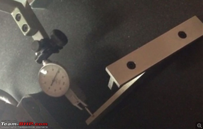
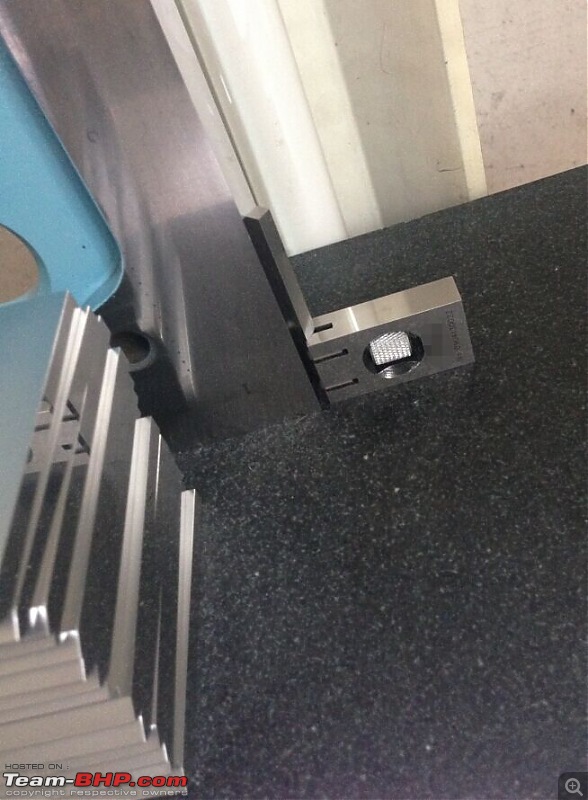
Second, all Dasqua products are strictly inspected and tested, such as 90° Square, our inspectors not only inspect the parallelism, straightness (see attachment), but also inspect each product by using LED light, ensure no light goes through between 90°Square and Standard inspection block (see attachment), so you don't worry about our product quality, we can give our customers 2 year quality guarantee, so we have confidence on our product quality.
These were the images attached to their mail:

DIY: Metal model engine building UPDATE: build complete (page 16)!-1.jpg

DIY: Metal model engine building UPDATE: build complete (page 16)!-2.jpg

DIY: Metal model engine building UPDATE: build complete (page 16)!-3.jpg

DIY: Metal model engine building UPDATE: build complete (page 16)!-4.jpg

I have also got an answer from Proxxon, I am going to take some more measurement and mail them back tonight

Jeroen

Last edited by Jeroen : 20th July 2020 at 17:20.
Jeroen is offline   (2) Thanks
Old 20th July 2020, 18:06   #32
Senior - BHPian
 
Join Date: Jul 2009
Location: Calcutta
Posts: 4,668
Thanked: 6,217 Times
re: DIY: Metal model engine building UPDATE: build complete (page 16)!

An individual calibration certificate bumps up costs tremendously. It is for this reason that for lower end shopfloor use equipment it is often more economical to periodically buy these from reputed manufacturers with manufacturers certificates than getting these recalibrated/ recertified every year or two.

But there should be a manufacturers certificate stating the standards to which it has been manufactured, and that it meets all the manufacturers standards, and somewhere on the manufacturers website these standards should be mentioned.

In the picture of the squareness test, I don't know what the spacer is doing. Beats the very purpose of the test. A little known fact, because it is observable only with the highest quality equipment, is that when the edges are just about to meet, the light will change colour to blue! (Don't know what happens with LED lights which do not have full spectrum).

Since you are getting into all this now, how you would draw/ make, ab initio, the perfect straight line. And prove it was a straight line.

Sutripta
Sutripta is offline   (2) Thanks
Old 20th July 2020, 18:45   #33
Senior - BHPian
 
Join Date: Jul 2009
Location: Calcutta
Posts: 4,668
Thanked: 6,217 Times
re: DIY: Metal model engine building UPDATE: build complete (page 16)!

^^^
DIN 875 marked on the blade. You are good to go!

If you don't mind, how much did it cost. Trying to equate it with costs in India.

Sutripta
Sutripta is offline   (2) Thanks
Old 20th July 2020, 19:27   #34
Distinguished - BHPian
 
Thad E Ginathom's Avatar
 
Join Date: Jun 2007
Location: Chennai
Posts: 10,999
Thanked: 26,418 Times
re: DIY: Metal model engine building UPDATE: build complete (page 16)!

Jeroen, for a task such as machining that block to size, how about a quick side project: a fly cutter?

Sutripta: advisable?
Thad E Ginathom is offline  
Old 20th July 2020, 20:23   #35
Distinguished - BHPian
 
Join Date: Oct 2012
Location: Delhi
Posts: 8,093
Thanked: 50,800 Times
re: DIY: Metal model engine building UPDATE: build complete (page 16)!

Quote:
Originally Posted by Thad E Ginathom View Post
Jeroen, for a task such as machining that block to size, how about a quick side project: a fly cutter?
Thad,
I did think about a fly cutter and some of my Dutch Model forum advise such as well. I have not gone that way for several reasons:

It doesn’t solve the problem of the allignement. If it is tramming, a fly cutter will cut a nice surface, but it won’t square up with the other sides.

Blondihack does a great video on her (initial) fly cutter problems and talks through all the various checks.


Making a good, we’ll balanced fly cutter is no small task. A project in itself, Blondihack has a two part video on it. Takes a lot of work. I could try and buy one, but then I run into the problem of my mill only taking these special collets and most fly cutters have different shafts. I am sure I could solve that too.

I might still go that way as I might have to do some more machining of fairly large surfaces on the supports. For now I want to try to get the alignment as precise as possible. I am making some very simple attachment so I can set up y dial better and more rigid than last time. And I’m going to take all the readings and a few more very precisely, see what I can adjust and what not. Mail that lot to Proxxon and see what they say.

I found some Youtube video’s on this very mill and it looks other folks are doing some pretty good machining, also in steel. So I’m convinced my could be doing a lot better. Truth be told, even on this cilinder support it doesn’t make a whole bunch of difference. These ever so slight water chutes are on the bottom and it’s perfectly square. Most of all the other cuts are going to be a lot less wide. And I have already experimented a bit with polishing away those last little bumps.

Still, I like to see how could I can get it, before proceeding. If the worst comes to the worst, who knows I might have to send the mill in for servicing. Once my other stock arrives I can get going on the lathe for quite a while.

Jeroen
Jeroen is offline   (1) Thanks
Old 20th July 2020, 20:25   #36
Senior - BHPian
 
Join Date: Jul 2009
Location: Calcutta
Posts: 4,668
Thanked: 6,217 Times
re: DIY: Metal model engine building UPDATE: build complete (page 16)!

Quote:
Originally Posted by Thad E Ginathom View Post
Jeroen, for a task such as machining that block to size, how about a quick side project: a fly cutter?

Sutripta: advisable?
Will need to be rigid and balanced. And will need variable speed (slow) with enough torque.

A lot depends on Proxxon supplying specialised attachments/ tools for its machines.

Sutripta
Sutripta is offline   (1) Thanks
Old 20th July 2020, 21:08   #37
Distinguished - BHPian
 
Thad E Ginathom's Avatar
 
Join Date: Jun 2007
Location: Chennai
Posts: 10,999
Thanked: 26,418 Times
re: DIY: Metal model engine building UPDATE: build complete (page 16)!

I guess it is important to get your mill set up as well as possible for any precision work in the future.

Ace Eurotrade is a nice site to browse . I wish I could find physical shops like that to visit in London area. I can find some pretty good general tool shops, and specialist jewellery tools, but I'd like somewhere where I can drool over the engineering stuff. Used to be more, But then, used to be more engineering factories to give them custom. One once-great street I used to know is now full of sari, gold, and Indian/Sri-Lankan-food shops! Well, I can't complain: I only know its current state because of friends living there. And I love the Siva temple
Thad E Ginathom is offline  
Old 21st July 2020, 12:19   #38
Distinguished - BHPian
 
Join Date: Oct 2012
Location: Delhi
Posts: 8,093
Thanked: 50,800 Times
re: DIY: Metal model engine building UPDATE: build complete (page 16)!

Quote:
Originally Posted by Thad E Ginathom View Post
I wish I could find physical shops like that to visit in London area.
The closest you have in the UK to my HBM here in the Netherlands is Machine Mart I guess. Not bad, they do have a large collection of all sorts of tools and specialised tools. Whenever we are in the UK, I always pop in

Quote:
Originally Posted by Sutripta View Post
^^^
DIN 875 marked on the blade. You are good to go!

If you don't mind, how much did it cost. Trying to equate it with costs in India.
Just under Euro 20.

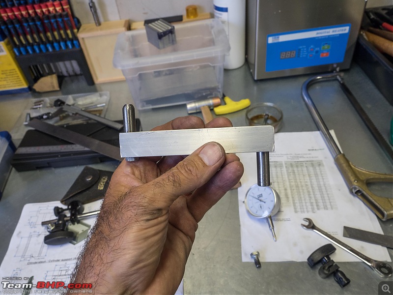
Last night I got going on re-doing the mill allignement. First thing, make sure I can take proper measurement. So I quickly put together this little tool, using a bit of Aluminium U profile and round bar I had lying around.

It will fit into the 10mm collet on the mill and it is plenty rigid!

DIY: Metal model engine building UPDATE: build complete (page 16)!-p7200001.jpg

Next I took two measurements, on the outer left and outer right of the table

DIY: Metal model engine building UPDATE: build complete (page 16)!-p7200002.jpg

DIY: Metal model engine building UPDATE: build complete (page 16)!-p7200003.jpg

As you can see, they are way off! About 0,25 mm across the full width of the table (260mm). Not sure what happened here first time. Maybe my measuring rig wasn’t stable/rigid enough, maybe I got the readings wrongs, maybe I did not tighten up the screws sufficiently. Most likely all of the above and some more.

One thing though; you can’t fix this quickly, unless you are very lucky. I tried quickly, before taking my wife out for dinner. Only made it worse. It is a delicate job, made worse by the fact that in order to swivel the head/column you obviously need to loosen up some bolts, which makes the reading go wonky. So the theory is you reduce the error by 50% into the direction of the error till you get close to zero on both readings. Well, it takes time. I will have another go tonight or tomorrow night. I want to try a few other measurements too.

Jeroen

Last edited by Jeroen : 21st July 2020 at 12:30.
Jeroen is offline   (4) Thanks
Old 21st July 2020, 14:06   #39
Senior - BHPian
 
Join Date: Jul 2009
Location: Calcutta
Posts: 4,668
Thanked: 6,217 Times
re: DIY: Metal model engine building UPDATE: build complete (page 16)!

Welcome to the joys of shall we call it thrifty machining.

One of the standard (thrifty) procedure used to be to buy a hefty but not too accurate vice, and machine it to ones standards. Plenty more like this. Your choice of time + skill vs money upfront! You are doing the same with your mill!

Suggest you get some basic things like V Blocks (sizes to match expected work), 123 blocks (both in pairs), Compass, Jenny, calipers (I prefer firm joint over spring), a carbide tipped scriber, marking block, and odds and ends as you need them. Once again, don't pick up junk.

You are picking up some bad habits. Like holding circular items between parallel jaws! Starts off as a necessity, but then becomes a self perpetuating. (I've done it thousands of times in the past etc.)

Oh, and for the surface plate, the Indian juggad is float glass. For home shop use, I prefer (aged seasoned) cast iron over granite.

Sutripta
Sutripta is offline   (3) Thanks
Old 22nd July 2020, 13:07   #40
Distinguished - BHPian
 
Join Date: Oct 2012
Location: Delhi
Posts: 8,093
Thanked: 50,800 Times
re: DIY: Metal model engine building UPDATE: build complete (page 16)!

Quote:
Originally Posted by Sutripta View Post
Welcome to the joys of shall we call it thrifty machining.
Me and my credit card are looking forward to that!


Quote:
Originally Posted by Sutripta View Post
Oh, and for the surface plate, the Indian juggad is float glass. For home shop use, I prefer (aged seasoned) cast iron over granite.
Yes, I have seen glass being used/suggested on some of youtube video’s too.

Managed to get some more alignment done last night:

I am also getting a lot of suggestion and support on my Dutch hobby forum. One guy has made me a very simple sort fly cutter. Should have that in a few days.

All in Dutch, but you will spot it here:

https://www.modelbouwforum.nl/thread....272629/page-2

I also got some tips on putting an adjustment screw on the head of my mill to facilitate the alignment. Have a look here:

https://www.modelbouwforum.nl/attach...01-jpg.385257/

But my mini mill is a lot smaller, so I need to think this through some more:

DIY: Metal model engine building UPDATE: build complete (page 16)!-p72100042.jpg

So I did manage to line up the milling head pretty precisely.

DIY: Metal model engine building UPDATE: build complete (page 16)!-p7210002.jpg

DIY: Metal model engine building UPDATE: build complete (page 16)!-p7210003.jpg

It’s definitely better than before, although admittedly difficult to tell from images

DIY: Metal model engine building UPDATE: build complete (page 16)!-p72100062.jpg

DIY: Metal model engine building UPDATE: build complete (page 16)!-p72100072.jpg

These little ridges, although visible, can hardly be felt. I ran my dial gauge over them too, just to get some idea on how big/small they are

DIY: Metal model engine building UPDATE: build complete (page 16)!-p72100082.jpg

DIY: Metal model engine building UPDATE: build complete (page 16)!-p72100092.jpg

Some different cuts:

DIY: Metal model engine building UPDATE: build complete (page 16)!-p72100102.jpg

DIY: Metal model engine building UPDATE: build complete (page 16)!-p72100112.jpg

Depending on the direction of the cut, I am measuring 0,01-0,02mm respectively 0,02-0,03mm. That is with a depth of 0,4-0,5mm. I am sure it will improve with a lighter cut. So I am getting a pretty good idea how to make the final cuts.

I have also mailed these final results to Proxxon, see what they say.

Materials are in the mail and so are some more goodies I ordered over the weekend!

Jeroen
Jeroen is offline   (1) Thanks
Old 22nd July 2020, 13:38   #41
Senior - BHPian
 
Join Date: Jul 2009
Location: Calcutta
Posts: 4,668
Thanked: 6,217 Times
re: DIY: Metal model engine building UPDATE: build complete (page 16)!

Quote:
Originally Posted by Jeroen View Post
I also got some tips on putting an adjustment screw on the head of my mill to facilitate the alignment. Have a look here:

https://www.modelbouwforum.nl/attach...01-jpg.385257/
IMO, that adjustment/ stopper setup is simply not rigid enough. Placebo.

Sutripta
Sutripta is offline  
Old 22nd July 2020, 14:29   #42
Distinguished - BHPian
 
Join Date: Oct 2012
Location: Delhi
Posts: 8,093
Thanked: 50,800 Times
re: DIY: Metal model engine building UPDATE: build complete (page 16)!

Quote:
Originally Posted by Sutripta View Post
IMO, that adjustment/ stopper setup is simply not rigid enough. Placebo.
Having spend, twice, about an hour and a half to try and straighten the mill head I think it could be useful. It is not about absolute rigidity perse.

This head swivels and is only held clamped with one bolt. You loosen it, it can swivel. I found it very difficult to loosen the bolt to the extend I could still swivel the head accurately. You still need a certain amount of friction. I tried different methods, slight tapping, attaching a big lever, to make it move etc.

So something that would have given me a better edge holding it towards a particular position would have been useful. You take the two readings, loosen the bolt, the reading changes considerable. From there on you need to put the adjustment in, re-tighten, take new readings etc. Especially when the adjustment become really small, such a simple device would have come into it’s own

Obviously, the more rigid, the better. But all I have now is the friction on the swivel mechanism controlled through the bolt.

Anyway, all academic now, as I did manage to get it almost spot on. But I can see having to do this multiple times over the months to come.

The cilinder support also has angled edges. I can mill those by either finding a way to clamp down the piece at the appropriate angle, or by swivelling the head.

Jeroen
Jeroen is offline   (1) Thanks
Old 22nd July 2020, 16:03   #43
Distinguished - BHPian
 
Thad E Ginathom's Avatar
 
Join Date: Jun 2007
Location: Chennai
Posts: 10,999
Thanked: 26,418 Times
re: DIY: Metal model engine building UPDATE: build complete (page 16)!

Quote:
Originally Posted by Jeroen View Post
I found it very difficult to loosen the bolt to the extend I could still swivel the head accurately. You still need a certain amount of friction.
This is a tilt head on mymonopod. Notice the white washers in the adjustment mechanism. This gives it a pseudo-fluid-head feel: the tension is adjustable. I wonder if a large washer like this between your mill head and its stand would help. Tight is certainly tight for the purpose shown here, but I am wondering if fully-tight would be tight enough for the mill head.

DIY: Metal model engine building UPDATE: build complete (page 16)!-monopodhead.jpg

No clue about plastics, so no idea of the material.
Thad E Ginathom is offline  
Old 22nd July 2020, 20:28   #44
Senior - BHPian
 
Join Date: Jul 2009
Location: Calcutta
Posts: 4,668
Thanked: 6,217 Times
re: DIY: Metal model engine building UPDATE: build complete (page 16)!

Quote:
Originally Posted by Jeroen View Post
So something that would have given me a better edge holding it towards a particular position would have been useful. You take the two readings, loosen the bolt, the reading changes considerable. From there on you need to put the adjustment in, re-tighten, take new readings etc. Especially when the adjustment become really small, such a simple device would have come into it’s own
Might work for fine adjustment if stiction does not defeat it. You'll need one on each side though. And the fixed end should have two widely spaced bolts holding it.

Does Proxxon have motors as accessories for the X and Y traverse/ feed?

Sutripta

Last edited by Sutripta : 22nd July 2020 at 20:30.
Sutripta is offline  
Old 23rd July 2020, 09:55   #45
Senior - BHPian
 
Join Date: Jul 2009
Location: Calcutta
Posts: 4,668
Thanked: 6,217 Times
re: DIY: Metal model engine building UPDATE: build complete (page 16)!

Quote:
Originally Posted by Jeroen View Post
These little ridges, although visible, can hardly be felt. I ran my dial gauge over them too, just to get some idea on how big/small they are
That;s a test indicator.
Neither a test indicator or a dial gauge will show surface roughness.

Quote:
Originally Posted by Jeroen View Post
The cilinder support also has angled edges. I can mill those by either finding a way to clamp down the piece at the appropriate angle, or by swivelling the head.
For the time being I'd just leave it square. The beautifying can be done later.
Don't see how angling the head will help you in this case.

Sutripta
Sutripta is offline   (1) Thanks
Reply

Most Viewed


Copyright ©2000 - 2024, Team-BHP.com
Proudly powered by E2E Networks