Team-BHP > Technical Stuff > DIY - Do it yourself
Register New Topics New Posts Top Thanked Team-BHP FAQ


Reply
  Search this Thread
83,817 views
Old 31st August 2020, 11:59   #106
Distinguished - BHPian
 
Join Date: Oct 2012
Location: Delhi
Posts: 8,080
Thanked: 50,641 Times
re: DIY: Metal model engine building UPDATE: build complete (page 16)!

Quote:
Originally Posted by Akash.D View Post
Since you have already spent some money in getting the tools, why not get a face milling cutter as well? The surface quality should drastically improve.
Thanks. I might look into that in the near future. The biggest challenge is my mini-mill. With the emphasis on mini. Those cutters might need a more powerful and rigid mill. I still have a fly cutter a friend of mine made for me. I still need to test it. Lets see how that goes first.

Jeroen
Jeroen is online now  
Old 3rd September 2020, 01:23   #107
Distinguished - BHPian
 
Join Date: Oct 2012
Location: Delhi
Posts: 8,080
Thanked: 50,641 Times
re: DIY: Metal model engine building UPDATE: build complete (page 16)!

A little bit more progress and some more (small) issues with Debbie.

So this evening I thought I would drill the various holes in the cylinder head, the cylinder bottom plate and the cylinder

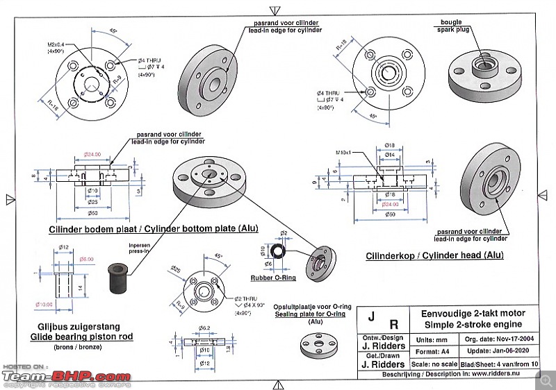
Have a look at the drawing. The thread in the cylinder needs to be M4, I have already bought the required hex bolts. End these need to be sunk / recessed (is that the correct term) into the cylinder head/bottom plate.

DIY: Metal model engine building UPDATE: build complete (page 16)!-debbie-sheet-4-cyliinder-plate.jpeg

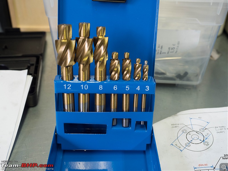
To this purpose I had bought a special set of hex bolt recess cutters (what is the proper English term for these). Anyway, when I opened them, they were the wrong kind. Correct packing, correct number, correct price, but the wrong bits!

This is what I got:

DIY: Metal model engine building UPDATE: build complete (page 16)!-p9020002.jpg

And this is what I thought I had bought:

https://www.hbm-machines.com/product...rzinkfrezenset

The reason I wanted to use these, is that it makes it somewhat more easy to keep the cutter properly centred on the drill hole.

I will need to exchange, if they havent got the proper ones, i will just use one of my 7mm cutter from my mini mill. Will work as well.

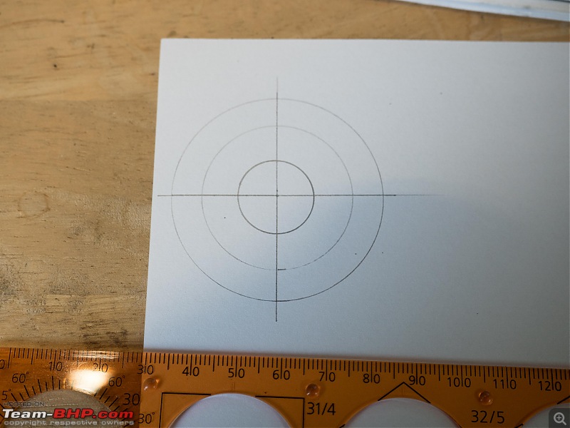
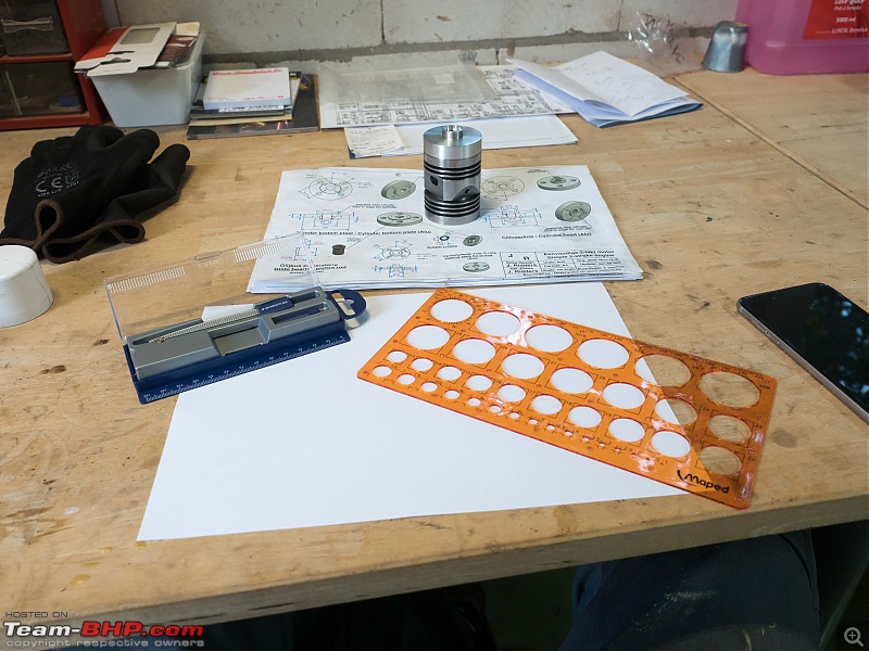
So I made my paper template

DIY: Metal model engine building UPDATE: build complete (page 16)!-p90200022.jpg

DIY: Metal model engine building UPDATE: build complete (page 16)!-p90200012.jpg

Some very carefully measuring and cutting. (or rather tapping. Just put the paper on the part gently tap with a aluminium/copper hammer around the edges that need to come out. Similar to how we used to make packings onboard the ships I used to sail on.

DIY: Metal model engine building UPDATE: build complete (page 16)!-p90200032.jpg

DIY: Metal model engine building UPDATE: build complete (page 16)!-p9020004.jpg

Centre holes are pretty accurate as far as I can tell and measure!

DIY: Metal model engine building UPDATE: build complete (page 16)!-p9020005.jpg

Also got started on the sealing plate for the O-ring. Fairly straightforward. Just the little recess that holds the O-ring was a bit of a fiddle to get right

DIY: Metal model engine building UPDATE: build complete (page 16)!-p9020006.jpg

DIY: Metal model engine building UPDATE: build complete (page 16)!-p9020007.jpg

I could not finish it. The whole needs to be 6,2mm and I don’t have that size. I tried 6,1mm which is the closest I had. But I am not entirely happy with it. The piston rod is going to be 6mm. So just 0,1mm clearance is a little on the low side. So I will order some new drill bits. Drill the hole and face of the part later.

Jeroen
Jeroen is online now   (4) Thanks
Old 3rd September 2020, 05:09   #108
Distinguished - BHPian
 
Thad E Ginathom's Avatar
 
Join Date: Jun 2007
Location: Chennai
Posts: 10,990
Thanked: 26,379 Times
re: DIY: Metal model engine building UPDATE: build complete (page 16)!

Quote:
bolt recess cutters (what is the proper English term for these)
Are they called countersink bits?
Thad E Ginathom is offline   (2) Thanks
Old 3rd September 2020, 13:39   #109
BHPian
 
Akash.D's Avatar
 
Join Date: Jun 2020
Location: JRH
Posts: 67
Thanked: 435 Times
re: DIY: Metal model engine building UPDATE: build complete (page 16)!

Quote:
Originally Posted by Jeroen View Post
... these need to be sunk / recessed (is that the correct term) ...
Jeroen
The technical term is countersinking.

As already mentioned above, they are countersink milling cutters.

Last edited by Akash.D : 3rd September 2020 at 13:42.
Akash.D is offline   (1) Thanks
Old 3rd September 2020, 13:59   #110
Senior - BHPian
 
Join Date: Jul 2009
Location: Calcutta
Posts: 4,668
Thanked: 6,217 Times
re: DIY: Metal model engine building UPDATE: build complete (page 16)!

The HBM catalogue calls these countersinks, but these are piloted counterbores. Best to use an Allen bolt, otherwise you have to give the clearance for a socket wrench. Does not look nice.
Can't figure out why you think you have got the wrong product.

For the end cap (and similar), it is best to lightly mark out the PCD while on the lathe. The problem with your approach is that the endcap is supposed to have rotational symmetry, but will in all probability will not.

O Ring groove - HSS has some advantages over carbide - you can form it on your bench grinder. (Use a soft white wheel. Though Indian juggadmasters will confidently tell you that the green wheels can grind/ form carbide).

Sutripta
Sutripta is offline   (1) Thanks
Old 6th September 2020, 12:21   #111
Distinguished - BHPian
 
Join Date: Oct 2012
Location: Delhi
Posts: 8,080
Thanked: 50,641 Times
re: DIY: Metal model engine building UPDATE: build complete (page 16)!

Quote:
Originally Posted by Sutripta View Post
The HBM catalogue calls these countersinks, but these are piloted counterbores. Best to use an Allen bolt, otherwise you have to give the clearance for a socket wrench. Does not look nice.
Can't figure out why you think you have got the wrong product.
The little pilot stub is way to large a diameter. Its almost 5mm. Since I have found out these sort of counterbores come in three distinct sizes:

https://www.toptools-ede.nl/producte...verzinkfrezen/

Sorry for the Dutch: Fijnpassing (fine), Mediumpassing (medium) and kerngat (not even sure how to translate it). The difference being the diameter of the pilotstub.

Quote:
Originally Posted by Sutripta View Post
For the end cap (and similar), it is best to lightly mark out the PCD while on the lathe. The problem with your approach is that the endcap is supposed to have rotational symmetry, but will in all probability will not.
I might give that a go next time. Getting the correct diameter on the lathe is not that easy either. I am not too worried though. There is going to be a little clearance due to clearances of the four little bolts holding it in place anyway.


Quote:
Originally Posted by Sutripta View Post
O Ring groove - HSS has some advantages over carbide - you can form it on your bench grinder. (Use a soft white wheel. Though Indian juggadmasters will confidently tell you that the green wheels can grind/ form carbide).
Yes, on my Dutch model building forum there are some purist who have separate drills, taps everything for different materials. But for hobby usage one needs to improvise a bit here and there.

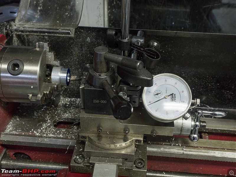
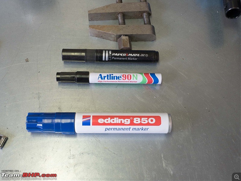
I finished the end cap lathe work yesterday. I have also been experimenting a bit with different felt pens. I recently got myself this very large one and it works very well for marking:

DIY: Metal model engine building UPDATE: build complete (page 16)!-p9050002.jpg

DIY: Metal model engine building UPDATE: build complete (page 16)!-p9050003.jpg

DIY: Metal model engine building UPDATE: build complete (page 16)!-p9050004.jpg

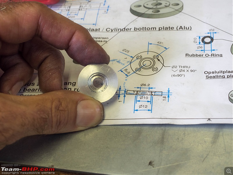
All ready for parting off. When I was nearly done, I suddenly realised I still need to drill the hole to 6.2mm. It was 6mm and I had ordered the 6.2mm drill bit and it had arrived in the mail earlier. So stopped the parting and managed to drill the hole to the correct diameter of 6.2mm.

DIY: Metal model engine building UPDATE: build complete (page 16)!-p9050005.jpg

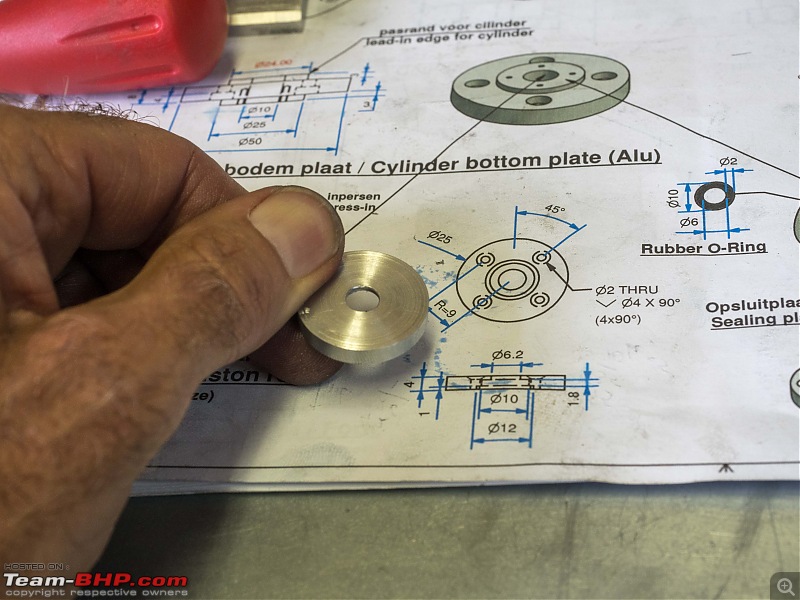
Looks fine and the sizing is pretty accurate too. Parting is going better and better. I did pause a few times to let the aluminium cool down a bit. Even with copious amount of cutting fluid the material heats up very quickly. I can sort of hear when the blades start getting stuck in between the groove. Just pull back, let everything settle and cool down and try again. That way when cutting it goes very smoothly, no judder, no drama!

DIY: Metal model engine building UPDATE: build complete (page 16)!-p9050007.jpg

DIY: Metal model engine building UPDATE: build complete (page 16)!-p9050008.jpg

Here it is put on top of the cylinder bottom plate.

DIY: Metal model engine building UPDATE: build complete (page 16)!-p9050009.jpg

Another template for the four bolt holts (did this before I read your post)

DIY: Metal model engine building UPDATE: build complete (page 16)!-p9050010.jpg

DIY: Metal model engine building UPDATE: build complete (page 16)!-p9050011.jpg

I also had to adjust the door of our shed. It was sagging a bit, so I fixed that. I keep a different set of tools in the shed. Whilst rummaging through it I came across this machinist clamp.

DIY: Metal model engine building UPDATE: build complete (page 16)!-p9050001.jpg

It needs a good cleaning/oiling. Its got a bit of very light surface rust. This clamp I made myself in 1976-1977. First year at naval engineering college. It was just about the first little project everybody had to do. All done to get everybody going on filing and threading. (No milling allowed).

I will clean it up, it might come in handy with my modelling.

Jeroen

Last edited by Jeroen : 6th September 2020 at 12:30.
Jeroen is online now   (3) Thanks
Old 6th September 2020, 13:06   #112
Senior - BHPian
 
Join Date: Jul 2009
Location: Calcutta
Posts: 4,668
Thanked: 6,217 Times
re: DIY: Metal model engine building UPDATE: build complete (page 16)!

Quote:
Originally Posted by Jeroen View Post
The little pilot stub is way to large a diameter. Its almost 5mm. Since I have found out these sort of counterbores come in three distinct sizes:

https://www.toptools-ede.nl/producte...verzinkfrezen/

Sorry for the Dutch: Fijnpassing (fine), Mediumpassing (medium) and kerngat (not even sure how to translate it). The difference being the diameter of the pilotstub.
OK. Get what you mean. Keep forgetting the size of the object you are dealing with!
Given the small sizes, countersink rather than counterbore might be a better idea. (You have to specify the countersink angle. Though many people seem to think 118 deg is a magical one size fits all number!)

You also get counterbores with interchangeable pilots.

Quote:
Getting the correct diameter on the lathe is not that easy either. I am not too worried though.
Mark, measure, correct. Assuming the handwheel is not a sloppy affair.


Quote:
Yes, on my Dutch model building forum there are some purist who have separate drills, taps everything for different materials.
No, I was saying form your own tools. Highly possible with HSS. Not really possible with carbide.


Quote:
All ready for parting off. When I was nearly done, I suddenly realised I still need to drill the hole to 6.2mm. It was 6mm and I had ordered the 6.2mm drill bit and it had arrived in the mail earlier. So stopped the parting and managed to drill the hole to the correct diameter of 6.2mm.
Hope you do know that a drilled hole is normally oversize! Though better on a lathe (work rotating) than on a drillpress (drill rotating).

Quote:
Even with copious amount of cutting fluid the material heats up very quickly.
Favoured 'cutting fluid' for Al is kerosene.

Quote:
I can sort of hear when the blades start getting stuck in between the groove. Just pull back, let everything settle and cool down and try again. That way when cutting it goes very smoothly, no judder, no drama!
As I've said the other problem is when a the chip wedges itself betwee the blade and the work. Much like stone chips in a brake caliper.

Quote:
Another template for the four bolt holts (did this before I read your post)
Much like say filing, layout and marking accurately with basic tools (the equivalent of geometric construction with compass and straightedge) is a very necessary skill/ knowledge, whether you actually use it or not. Workshop textbooks should help.

Was wondering in your part of the world, what access a hobbyist has to services which a professional takes for granted. Like say tool sharpening, heat treatment, hard chrome plating etc.

Sutripta
Sutripta is offline   (1) Thanks
Old 6th September 2020, 13:52   #113
Distinguished - BHPian
 
Join Date: Oct 2012
Location: Delhi
Posts: 8,080
Thanked: 50,641 Times
re: DIY: Metal model engine building UPDATE: build complete (page 16)!

Quote:
Originally Posted by Sutripta View Post
Was wondering in your part of the world, what access a hobbyist has to services which a professional takes for granted. Like say tool sharpening, heat treatment, hard chrome plating etc.
a
To a large extend you could probably find these sort services if you need them. The biggest problem for hobbyist would be cost. The minute you need to pay commercial rates for the work it tends to become very very expensive. A commercial rate for a workshop mechanic is easily € 65 - 75 per hour.

Some of these services are well known to the classic car enthusiast. E.g. all kinds of plating processes. And they are easily available. Cost is a different factor on car to model building. When you are restoring a car you would consider originality versus new and the cost associated. I have had some of my Spider parts rechromed, because I prefer the original parts to getting new ones. Cost wise there isn’t that big a price difference either. And when getting it re-chromed I get to pick and choose the type of chroming proces used, quality etc.

I know of some guys who had to get a few DIY gear box parts heat treated and they managed to find a small specialised shop that helped them out.

So what really helps is to know people that can introduce you to professional companies that might be happy to help out the occasional hobbyist at a fair price.

There are still lots of relatively small outfits that undertake all kinds of highly specialised jobs/services. So it is really about finding them and finding a way to engage with them, without breaking the bank.

Slightly different topic:

You might find this Blondihack project interesting; Some weeks ago she started this project on building a steam engine from a casting kit. I had been looking at these kits before. I was under the misunderstanding that it would be relative easy. (As you will see, big mistake! These casting kits are not for the novel model engine builder I think)

She into her fifth episode already. Love the detail she is showing on how she goes about it, plans it out, makes mistakes:

Jeroen is online now   (2) Thanks
Old 12th September 2020, 20:02   #114
Distinguished - BHPian
 
Join Date: Oct 2012
Location: Delhi
Posts: 8,080
Thanked: 50,641 Times
re: DIY: Metal model engine building UPDATE: build complete (page 16)!

Finally got around to drilling and tapping the first set of holes

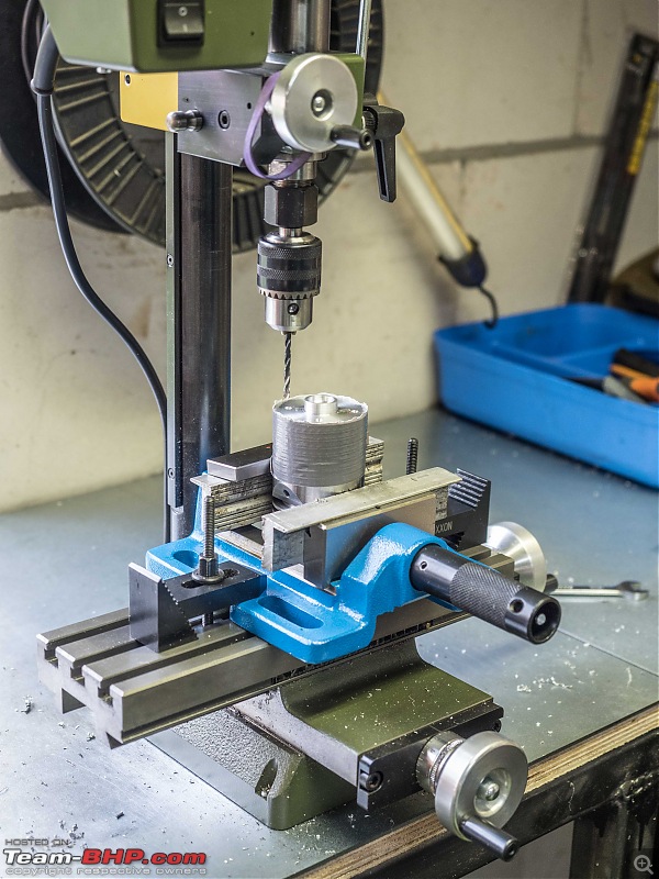
Also, first time I got to use my new machine clamp.

DIY: Metal model engine building UPDATE: build complete (page 16)!-p9110001.jpg

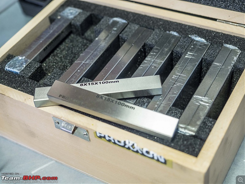
Also, first time I got to use this fancy set of parallel bars!

DIY: Metal model engine building UPDATE: build complete (page 16)!-p9110002.jpg

Got this countersink bore, one with exact dimensions I was looking for:

DIY: Metal model engine building UPDATE: build complete (page 16)!-p9110003.jpg

Bit of thread tapping

DIY: Metal model engine building UPDATE: build complete (page 16)!-p9110004.jpg

Done! Cilinder head looks quite nice!

DIY: Metal model engine building UPDATE: build complete (page 16)!-p9110005.jpg

DIY: Metal model engine building UPDATE: build complete (page 16)!-p9110006.jpg

Jeroen
Jeroen is online now   (4) Thanks
Old 17th September 2020, 01:45   #115
Distinguished - BHPian
 
Join Date: Oct 2012
Location: Delhi
Posts: 8,080
Thanked: 50,641 Times
re: DIY: Metal model engine building UPDATE: build complete (page 16)!

Managed to make quite a bit of progress over the last few days:

In order to drill the holes for the four tiny bolts in the sealing plate, to align properly with the holes in the cylinder, I secured the sealing plate to the cylinder bottom plate with a bolt, some washers and a nut.

DIY: Metal model engine building UPDATE: build complete (page 16)!-p9150001.jpg

Next drilled them right through with the appropriate drill, 1.6mm as the thread is M2. I wanted the little bots countersunk, but I don’t have anything this small, so a normal drill bit had to suffice

DIY: Metal model engine building UPDATE: build complete (page 16)!-p9150002.jpg

the tapping of the M2 thread was a bit nerve wrecking. You do not want to break the tap! And believe me M2 is tiny tiny!

DIY: Metal model engine building UPDATE: build complete (page 16)!-p9150003.jpg

End result, pretty satisfied!

DIY: Metal model engine building UPDATE: build complete (page 16)!-p9150004.jpg

First time the cylinder bottom plate with the sealing plate for the O-ring on the piston rod, assembled with the cylinder!

DIY: Metal model engine building UPDATE: build complete (page 16)!-p9160006.jpg

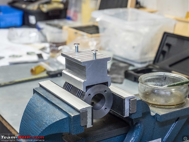
Next I still had to tap the thread into injecting gas mix hole of the cylinder. Just for reference I wanted it properly clamped into my vice. So using one of my parallel bars to get the correct orientation

DIY: Metal model engine building UPDATE: build complete (page 16)!-p9160007.jpg

DIY: Metal model engine building UPDATE: build complete (page 16)!-p9160008.jpg

DIY: Metal model engine building UPDATE: build complete (page 16)!-p9160009.jpg

And here the M6 tap goes in (in fact I used three taps)

DIY: Metal model engine building UPDATE: build complete (page 16)!-p9160012.jpg

When I am working late at night in my garage I like to drink some coffee, in all honesty I am quite the coffee junk. So coffee is served in very appropriate, very manly Nurnburgring cups!

DIY: Metal model engine building UPDATE: build complete (page 16)!-p9160011.jpg

Next I wanted to drill the intake and compression hole on the cylinder. But there was a problem!

DIY: Metal model engine building UPDATE: build complete (page 16)!-p9160013.jpg

My new machine clamp is too big! Or as I told my wife, my mini mill is to little!

So a bit of improvisation and this worked fine. Drilling with good new sharp drill bits in this pearlitic cast iron goes very smoothly.

I use this long rod to line up the cylinder, I can take a few measurements as well.
Works good enough

DIY: Metal model engine building UPDATE: build complete (page 16)!-p9160014.jpg

Following the same method I also drilled two more holes and tapped them (M5) to mount the cylinder onto the Cylinder support. The bolts will be going through the foundation plate as well. So I might still have to cut them to the correct length.

DIY: Metal model engine building UPDATE: build complete (page 16)!-p9160016.jpg

It means all the holes in the cylinder are now done. Except the two little ones for the mounting block of the muffler. These will be two more M2s holding it together. I want to make the mounting block first and use it for orientation where to drill these last two little holes. These are not through and through.

So I can give the cylinder another good honing. Next the piston and piston rod and the glide bearing piston rod!

Jeroen
Jeroen is online now   (3) Thanks
Old 20th September 2020, 20:58   #116
Distinguished - BHPian
 
Join Date: Oct 2012
Location: Delhi
Posts: 8,080
Thanked: 50,641 Times
re: DIY: Metal model engine building UPDATE: build complete (page 16)!

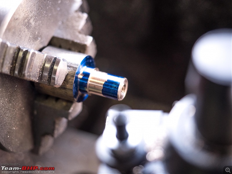
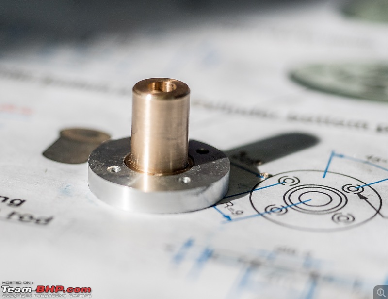
Friday night I got going on the glide bearing for the piston rod. It’s made out of bronze. I had plenty!

DIY: Metal model engine building UPDATE: build complete (page 16)!-p9190001.jpg

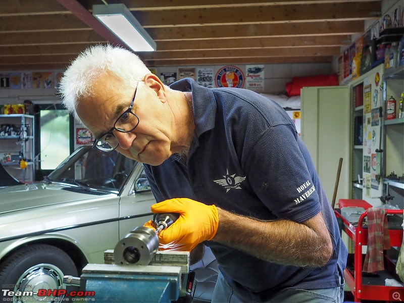
Some carefully measuring on the lathe. Lots of critical measurements on this one!

DIY: Metal model engine building UPDATE: build complete (page 16)!-p9190003.jpg

Very pleased with how it turned out:

DIY: Metal model engine building UPDATE: build complete (page 16)!-p9190004.jpg

It is a perfect fit into the recess I made earlier in the cylinder bottom plate. Initially it was sitting a fraction high, but I just used a bit of polishing paste to get it perfect!

DIY: Metal model engine building UPDATE: build complete (page 16)!-p9190005.jpg

Next it needs pressing into the cylinder head. Once it is properly fitted into the cylinder head I will drill and ream the hole to required 6mm for the piston rod

Jeroen

Last edited by Jeroen : 20th September 2020 at 21:00.
Jeroen is online now   (3) Thanks
Old 20th September 2020, 21:12   #117
Team-BHP Support
 
Gannu_1's Avatar
 
Join Date: Apr 2013
Location: Madras
Posts: 7,174
Thanked: 20,219 Times
re: DIY: Metal model engine building UPDATE: build complete (page 16)!

Got to give it to you for painstakingly documenting each step of the machining process with the snaps and write-ups!

Good luck for the build. Looking forward for the model engine.
Gannu_1 is offline   (2) Thanks
Old 24th September 2020, 13:18   #118
Distinguished - BHPian
 
Join Date: Oct 2012
Location: Delhi
Posts: 8,080
Thanked: 50,641 Times
re: DIY: Metal model engine building UPDATE: build complete (page 16)!

Last night some more progress and one small set back. I also received a spark plugs and some o-rings from a fellow model engine builder from my Dutch forum. I have been receiving all kinds of help and items, he kindly posted these to me.

DIY: Metal model engine building UPDATE: build complete (page 16)!-p9230001.jpg

My drawings do include a spark plug and I have also all the materials. Even so, producing this model engine is one thing, getting it to actually run is going to be another thing together. I have been in touch with two guys who made this model, looks really good, but they could not get it to run. So I figure I will try it with a proper ready made spark plug first. If I do, eventually get it to run, I will then fabricate the DIY spark plug. One less variable to worry about.

We were supposed to meet up this Saturday as we had both enrolled for this workshop soldering. Alas, the workshop got cancelled. Not enough interest, personally, I think it is still Covid related. I see the same with my RPS Photography club. People love the virtual meets, will show up for meetings outside, but workshop inside is to much for most. I will have to cancel our next RPS Photography as well. Shame, very interesting topic and we had an excellent photographer lined up.

Back to model engines:

I pressed the glide bearing into the cylinder plate. I put the cylinder plate in my wife’s oven at 85oC and the bearing in the freezer at -18oC. Left them for 30 minutes, took them out and put them together. Very little force was needed!

DIY: Metal model engine building UPDATE: build complete (page 16)!-p9230002.jpg

Looks really good, very pleased with this so far:

DIY: Metal model engine building UPDATE: build complete (page 16)!-p9230003.jpg

DIY: Metal model engine building UPDATE: build complete (page 16)!-p9230004.jpg

Then back into the lathe for the final boring and reaming. All done. I checked the fitment of the sealing plate, with the O-ring and the bearing in place. Looks good, so on to the next job: Honing

As I had drilled some more holes into the cylinder I needed to do some more honing on the cilinder. Out comes the honing device and my electric drill.

DIY: Metal model engine building UPDATE: build complete (page 16)!-p9230006.jpg

I spend about 30 minutes honing and as far as I can tell by eye and by feel this is as good as it gets. Next the piston. This is where things went wrong. Not sure what I did wrong, but I managed to turn the round bar to a too small diameter. Not by much. The tolerance of the piston in the cylinder is supposed to be around 0,03 - 0,05 mm. And I have already more and that is before I started polishing.

DIY: Metal model engine building UPDATE: build complete (page 16)!-p9230010.jpg

Luckily I have another piece of this round bar left. Should just manage to cut a piston head out of it.

Jeroen
Jeroen is online now   (2) Thanks
Old 24th September 2020, 16:34   #119
Distinguished - BHPian
 
Thad E Ginathom's Avatar
 
Join Date: Jun 2007
Location: Chennai
Posts: 10,990
Thanked: 26,379 Times
re: DIY: Metal model engine building UPDATE: build complete (page 16)!

Thanks for the ongoing story and the great photos.

I'm amazed that anyone would actually make the spark plug themselves. What would be the material for the insulator? I'm guessing that there is not a machinable ceramic? Well, I could be wrong: I suppose there are many weird ceramics. Like the ones they make machine tools out of.
Thad E Ginathom is offline  
Old 24th September 2020, 18:56   #120
Distinguished - BHPian
 
Join Date: Oct 2012
Location: Delhi
Posts: 8,080
Thanked: 50,641 Times
re: DIY: Metal model engine building UPDATE: build complete (page 16)!

Quote:
Originally Posted by Thad E Ginathom View Post
I'm amazed that anyone would actually make the spark plug themselves. What would be the material for the insulator? I'm guessing that there is not a machinable ceramic? Well, I could be wrong: I suppose there are many weird ceramics. Like the ones they make machine tools out of.
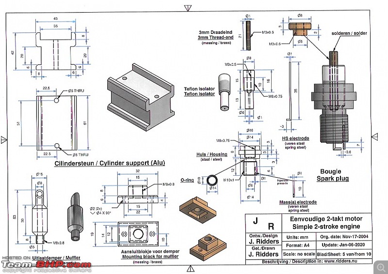
The insulator is just teflon. See this drawing:

DIY: Metal model engine building UPDATE: build complete (page 16)!-debbie-sheet-5-spark-plug.jpeg

I guess I could even make the insulator out of Delrin? In my fiddling with cars thread I have shown the High Voltage adapter for my Sourieau Engine Analyser. The outside (insulator) I made out of Delrin too.

Not sure what would be easier to machine teflon or Delrin. Never tried machining Teflon yet. We will see once we get there. Still a long way to go before I start worrying about the DIY spark plug!

Jeroen
Jeroen is online now   (2) Thanks
Reply

Most Viewed


Copyright ©2000 - 2024, Team-BHP.com
Proudly powered by E2E Networks