Team-BHP > Shifting gears > Gadgets, Computers & Software
Register New Topics New Posts Top Thanked Team-BHP FAQ


Reply
  Search this Thread
34,667 views
Old 9th August 2020, 01:27   #46
Newbie
 
Join Date: Jun 2020
Location: Bangalore
Posts: 8
Thanked: 34 Times
Re: DIY - UPS for the router

Quote:
Originally Posted by fordday View Post
Above mentioned board is not available. Do you think this board will work ? Link
The board should work in my opinion. The maximum current output is 25A. However,the router will take what is needed. Normally, routers are of 12V2A max. Haven't come across a one which needs more power.
cooljais is offline  
Old 9th August 2020, 09:20   #47
BHPian
 
whitewing's Avatar
 
Join Date: Oct 2012
Location: Bangalore
Posts: 561
Thanked: 1,584 Times
Re: DIY - UPS for the router

Quote:
Originally Posted by Route66 View Post
.....
Then came the first power cut. Router did not restart and my laptop was showing connected to WiFi. But internet would not work. It happened again when power came back.

I started trouble shooting and found that the Switch installed by the ISP in our apartment building is not connected to backup power. So the switch restarts every-time there is a power cut and when power comes back. In the end, money and time wasted and I was back to square one.
Had exactly the same experience, on following up with the ISP (ACT broadband) found out that though their router has provision for hooking up to battery backup, but they had not installed the battery. A few followups/tickets later, a tech came over and slotted in a lead acid battery. The battery was hooked to the router itself.
whitewing is offline   (1) Thanks
Old 7th September 2020, 20:28   #48
BHPian
 
Join Date: Aug 2014
Location: DEL, SFO
Posts: 901
Thanked: 2,838 Times
Re: DIY - UPS for the router

I bought one of these tiny router UPSs from Zinq technologies via Amazon. It looks exactly like the resonate one. On using it with my fiber modem which is 12V, 2A just as per the specification of the UPS, I have discovered a strange situation. If I manually turn off the power at the switch or by pulling out the power connector, the UPS holds the modem fine. I even tried it for ten minutes. However during an actual power failure, the UPS doesn’t retain power to the modem. I simulated a power failure by shutting the circuit breaker as well with the same result. I wonder what could be the reason? Could it be that the current flows back towards the adapter?
Lobogris is offline  
Old 8th September 2020, 10:21   #49
BHPian
 
Join Date: Dec 2005
Location: bang
Posts: 878
Thanked: 3,117 Times
Re: DIY - UPS for the router

Hmm..Interesting. If you could share some photos of the UPS along with data sheets it would be useful. Probably there are some setting switches or something.

Quote:
Originally Posted by Lobogris View Post
If I manually turn off the power at the switch or by pulling out the power connector, the UPS holds the modem fine
If you are pulling out the adapter wire which runs between the power adapter ( AC/DC) and the UPS, it wont affect the the UPS OUTPUT line to the Modem since the battery is built into UPS. It would run continuously till battery runs out i.e more than 10mins.

Quote:
However during an actual power failure, the UPS doesn’t retain power to the modem. I simulated a power failure by shutting the circuit breaker as well with the same result. I wonder what could be the reason?
Pl check the documentation. If this is to be used as a stand alone unit during working without the adaptor.


Quote:

Could it be that the current flows back towards the adapter?
I don't think so. You can also check if the female jack on the USP AC/DC power adapter IN line, is having any terminal voltage when power adapter is pulled out and is also supplying the modem. Just take any multi and check the voltage between the center pin and the cylindrical base surrounding it. To confirm you can also connect a load say 12V Bulb using a male connector. If it has a terminal voltage i am not sure what to make of it.

Anyway as i said please check the documentation for any clues.

P.S Zing Technologies : Chinese?.

Last edited by srini1785 : 8th September 2020 at 10:24.
srini1785 is offline   (1) Thanks
Old 8th September 2020, 11:02   #50
BHPian
 
Join Date: Aug 2014
Location: DEL, SFO
Posts: 901
Thanked: 2,838 Times
Re: DIY - UPS for the router

Quote:
Originally Posted by srini1785 View Post
P.S Zing Technologies : Chinese?.
It claims made in India and is supposedly made by a company in Delhi but is obviously rebadged Chinese. It looks exactly like Resonate and many other brands. Exactly same box, same connectors and everything else. After speaking to their customer service, I have requested a replacement.
Lobogris is offline   (1) Thanks
Old 17th September 2020, 12:45   #51
BHPian
 
Join Date: Aug 2014
Location: DEL, SFO
Posts: 901
Thanked: 2,838 Times
Re: DIY - UPS for the router

Quote:
Originally Posted by Lobogris View Post
It claims made in India and is supposedly made by a company in Delhi but is obviously rebadged Chinese. It looks exactly like Resonate and many other brands. Exactly same box, same connectors and everything else. After speaking to their customer service, I have requested a replacement.
To provide an update, the replacement came within two days and is working fine.
Lobogris is offline   (2) Thanks
Old 14th January 2021, 10:08   #52
BANNED
 
Join Date: Mar 2007
Location: Kolhapur
Posts: 1,717
Thanked: 1,901 Times
Re: DIY - UPS for the router

What's the best place to get a 18650 battery? Most places seem to sell fake ones. I am looking for an authentic Sony vtc6 or something of a similar quality?
carboy is offline  
Old 14th January 2021, 10:23   #53
BHPian
 
bejoy's Avatar
 
Join Date: Mar 2004
Location: Bangalore
Posts: 924
Thanked: 1,405 Times
Re: DIY - UPS for the router

Quote:
Originally Posted by carboy View Post
What's the best place to get a 18650 battery? Most places seem to sell fake ones. I am looking for an authentic Sony vtc6 or something of a similar quality?
I have had good success with Robu.in in getting good quality batteries.

https://robu.in/product/samsung-inr1...i-ion-battery/
bejoy is offline   (1) Thanks
Old 13th April 2023, 16:26   #54
BHPian
 
Join Date: Dec 2020
Location: Chennai
Posts: 52
Thanked: 344 Times
Re: DIY - UPS for the router

This is an old thread, but wanted to share my build for the Router UPS.

The entire build costs about Rs. 700 and you get 1 extra 18650 Li-ion Cell.

I got the circuit idea from this YouTube video.
I adapted the circuit to work on a 2S2P pack.(7.4V and 4000mAh)
The pack gives me about 8 hours of backup for a D-Link DIR 819 (needs 12v at 0.7A).
It gets charged in about 3-4 hours. (I haven't modified the TP 5100 module to set my charging current at C/10. The default is 2000mAh, which is around C/2 and I have continued using the same.)

I apologise for the poorly modified schematic, but I hope it's well readable.

DIY - UPS for the router-fz7wsmmkt1iezyz.png
The modified schematic.

BOM:

1* TP 5100 Rs.70
1* HX-2S-A2 Rs. 50
1* XL6009E1 Rs.75
1* Power MOSFET IRF9540 Rs. 45
4* IN 5822 Diode Rs. 40
1* DC barrel jack Male & Female (or whatever adapter your router input uses) Rs. 40
Fuses, Resistors Wires & other misc. Rs. 50
10000 mAh powerbank Rs.400 (I buy Rock powerbanks during online sales and get 5 2000 mAh cells. This build uses 4 and leaves me with 1 more for another project.)


DIY - UPS for the router-img20230413wa0010.jpg
The TP 5100 module

The TP 5100 is a charging module which can be used for both 1S and 2S packs. It has a wide input voltage of 5-15V, which in our cases fits most router adapters. The charging voltage can be set by creating a solder bridge between the 2 solder pads marked SET. It has a max charging current of 2A which is also the default but can be changed by changing the Rprog resistor. It also has a bi-LED which shows the charging status.

DIY - UPS for the router-img20230413wa0013.jpg
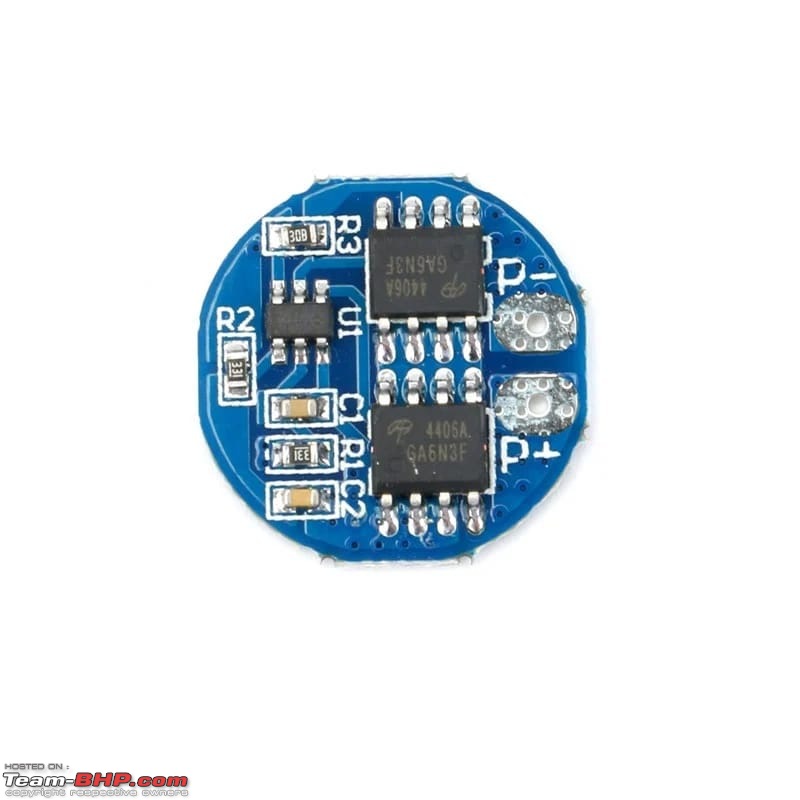
HX-2S-A2 2S BMS module

The HX-2S-A2 module is a 2S BMS. It is not a CHARGING MODULE. It is suited for low power 2S applications where the max current draw is around 5-6A, and is perfect for this use case.


DIY - UPS for the router-img20230413wa0014.jpg
XL 6009E1 Boost converter

The XL6009E1 is the boost converter. It requires a minimum input voltage of 5V to work. Websites such as Robu,eBay and others have the input voltage as 3V which is wrong.
Giving it an input voltage below 5V, it will be possible to set the output voltage to required level under no load conditions. Once load is attached, the voltage will drop or will give out the magic smoke and fail spectacularly in a few hours time.

The IRF 9540 MOSFET is used for the switching application. That is when power from Mains is available, it supplies both the router and the charging module, when mains power is lost, it switches from the mains to the battery pack. This is essential because most charging modules are not to be used with the load connected to the battery pack, since when in CV mode (Constant Voltage) the resting voltage of the batteries will never truly be acheived and the charger will keep pushing the higher voltage to the cell, which isn't very good for cell health in the long run.

Instead of using a MOSFET, you can use a Switch, but that would mean you need to switch it on and off each time and it wouldn't be quite automatic.

The IN 5822 diodes are to prevent backflow of current, both the Mains and the UPS. These diodes have a low forward drop voltage and hence are better suited and can also handle higher current.

The fuse is to prevent the battery pack from either receiving or giving too much current and in the process burning up.

Right now, I have housed the entire build in a random plastic box which hangs via a thread from the screws drilled into the wall for the router.
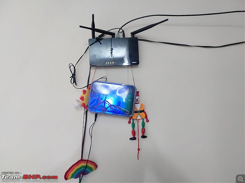

DIY - UPS for the router-img20230413wa0012.jpg
please excuse the poor quality of the photo and the accompaniments on the side. I know it looks absolutely hideous.

But I am planning on getting a 3d printed case soon. I have been forbidden from drilling holes into the wall and I doubt regular double sided tape will hold the weight, so I have decided to use command hooks with indents on the back of the case to hold it in position.


Why use 2S, why not use 3S as in the video or a 1S pack?

The reason I did not use a 3S pack was because I have not been able to find a 3S charging module. Most builds use a CC/CV module which is more expensive and is rated for more higher current and in my opinion would be wasted in this build.

As for 1S, the first time I tried building this, I used a 1S3P pack, but for some reason the router would keep restarting. On checking voltages, the no load voltage from the XL6009 boost converter was 12V, however on connecting the router, this dropped to 6V. It was then that I found the minimum input voltage of the XL6009. I could have substituted the Boost module for a MT3608 which can indeed handle the 3.7V, but by then I had ordered the BMS and charging module and hence stuck to that. But yes, a 1S pack will work well when the Boost converter is changed to MT3608. However, please note that the MT 3608 can only source 2A, while this should be enough for most midrange routers, please make sure you read the input current for your router before you go down this road and note that a small heatsink would be a must in this case.

I have a problem with the MOSFET, for which if someone can point me in the right direction, I would be grateful.

The MOSFET when switching from UPS to Mains (ie, power comes back on) does so immediately (ie. no router restart) but when switching from Mains to UPS (power goes off), causes the router to restart. I wonder why this occurs. I did read the datasheet of the IRF 9540 but the switching speed seems to be very fast, so I don't seem to understand why this occurs.

Hope this helps.

Regards,
alphamike_1612
alphamike_1612 is offline   (3) Thanks
Old 13th April 2023, 16:47   #55
BHPian
 
Join Date: Dec 2005
Location: bang
Posts: 878
Thanked: 3,117 Times
Re: DIY - UPS for the router

Quote:
Originally Posted by alphamike_1612 View Post
but when switching from Mains to UPS (power goes off), causes the router to restart. I wonder why this occurs. I did read the datasheet of the IRF 9540 but the switching speed seems to be very fast, so I don't seem to understand why this occurs.
Connect a 15V capacitor at the terminal end of the UPS. During switching ON/OFF this would help maintain the terminal voltage. It would eat up come current i'm afraid.
srini1785 is offline   (1) Thanks
Old 13th April 2023, 23:19   #56
BHPian
 
Join Date: Dec 2020
Location: Chennai
Posts: 52
Thanked: 344 Times
Re: DIY - UPS for the router

Quote:
Originally Posted by srini1785 View Post
Connect a 15V capacitor at the terminal end of the UPS. During switching ON/OFF this would help maintain the terminal voltage. It would eat up come current i'm afraid.
Thank you @srini1785.
I did try this with a 1000 uf capacitor, however, the effect is still the same. There is a restart when switching between Mains and UPS.
I was thinking it was related to the MOSFET switching, since the input of both the adapter and the battery is connected to the Step Up module.
Am I going down the wrong path?

Last edited by alphamike_1612 : 13th April 2023 at 23:22.
alphamike_1612 is offline  
Old 14th April 2023, 13:47   #57
BHPian
 
Join Date: Dec 2005
Location: bang
Posts: 878
Thanked: 3,117 Times

Quote:
Originally Posted by alphamike_1612 View Post
Thank you @srini1785.
I did try this with a 1000 uf capacitor, however, the effect is still the same. There is a restart when switching between Mains and UPS.
I can think of three possible remedies, one of which you have already tried. If you have a oscilloscope, measure the volts when you switch between points A and B. Whether during switching it goes below or above 12V which causes the router to restart.
DIY - UPS for the router-capacitor.jpg

The second is to use a Zener diode which when properly biased would maintain the terminal volts across its ends.
DIY - UPS for the router-zener.jpg

The third is to use a LC filter circuit which would limit the spikes that appear on the output. This is a bit more complicated and keep this to the last.
DIY - UPS for the router-lc-filter.jpg

Quote:
I was thinking it was related to the MOSFET switching, since the input of both the adapter and the battery is connected to the Step Up module.
Am I going down the wrong path?
I am not familiar with the Mosfet model that you are using. It may be that the voltage at the source is dropping when switched to the drain.You can equally try a Transistor of same capacity or just ditch all these semiconductors and try out a simple relay.

PS: Try checking with that diode removed (IN5822).

I just realized that for the Zener to work, its terminal volts should be greater that 12V. So its probably ruled out.

Mods : Pl mearge with previous post if possible.

Last edited by navin : 14th April 2023 at 16:20.
srini1785 is offline   (2) Thanks
Old 26th April 2023, 01:30   #58
BHPian
 
Join Date: Dec 2020
Location: Chennai
Posts: 52
Thanked: 344 Times
Re: DIY - UPS for the router

Quote:
Originally Posted by srini1785 View Post
I can think of three possible remedies, one of which you have already tried.

Thank you @srini1785 for those amazing workarounds.

However my problem seems to have been a rookie mistake, infact, it feels a little foolish to say this, but my MOSFET seems to have been faulty (must have been due to exposing it to too much heat while soldering).
I realised it only after I found out the MOSFET was heating up to abnormally high levels and eventually failed entirely.

Replacing the MOSFET and adding a 1000uf cap after the diodes ensured there was no reset.
alphamike_1612 is offline   (1) Thanks
Reply

Most Viewed


Copyright ©2000 - 2024, Team-BHP.com
Proudly powered by E2E Networks