Team-BHP > Technical Stuff
Register New Topics New Posts Top Thanked Team-BHP FAQ


Reply
  Search this Thread
77,939 views
Old 28th December 2005, 15:38   #1
Team-BHP Support
 
Rehaan's Avatar
 
Join Date: Feb 2004
Location: Bombay
Posts: 24,039
Thanked: 34,069 Times
Pics: Carbon Fiber Seat - How it was handmade for FSAE

Okay,

It has been a long time since i was supposed to put this thread up, but better late than never!

A bit of background
Formula SAE is basically an engineering competition, where each of the ~150 engineering schools that take part build a racecar within the rather comprehensive set of rules set down by the competition.
Teams are judged on four events - skidpad, acceleration, endurance, and autocross, as well as on other factors like cost report, design and presentation.


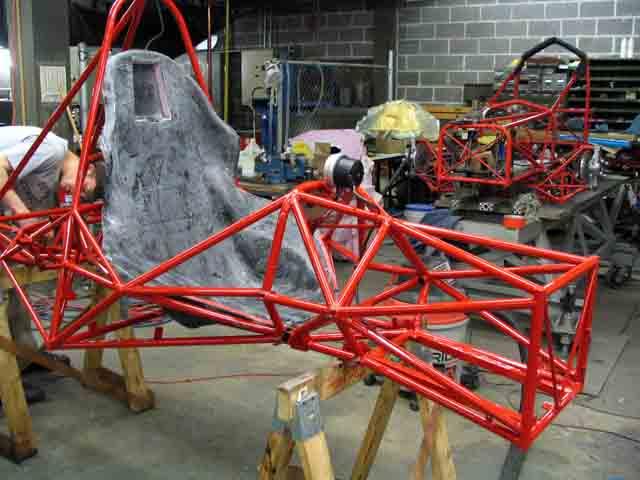
One of the things i was part of with the Brown University FSAE team was fabricating a seat for the car.

A friend and i were given the CAD drawings of the frame that was already designed and told to integrate a seat however we wanted.


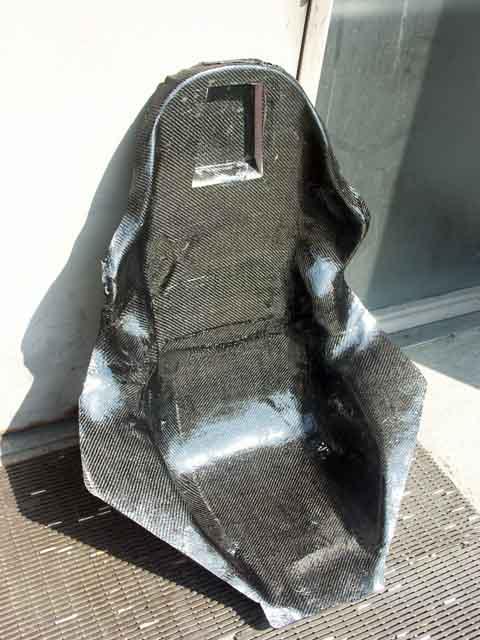
The seat was to be made from carbon fiber, for its clear advantages in terms of strength and weight. As you can see from the picture above, we decided to take a non-conventional approach and extend the "wings" of the seat all the way to the tubing. Originally we planned to bond the seat directly onto the chassis. However, the seat needed to be removable for inspecting the engine, so then we played with the idea of a two part seat.
In the end, we fixed upon a single piece seat which would be removable (not bonded to the chassis, but bolted).


Even though this massive winged seat would me marginally heavier than a typical "go-kart" like seat, it would have a much larger weight saving overall, due to the fact that it eliminates two things -
1. The floorpan
2. The firewall (Rules say that no part of the driver should be in direct line of sight with any part of the fuel, lubrication or cooling systems.)

So as you can see in the image above, the final seat was constructed in CAD. We then proceeded to cut the computer model into 2" sections and printed out the cross section of the seat at those 2" intervals.
We then cut 2" sheets of polystyrene foam along those profiles, and then glued them all together to form one big rough seat.


Then was the "fun" part of sanding it down. Keeping a close eye on symmetry. (Luckily i was out of town during this part of the mould making )


Then, there were several options as to how we could proceed to make the seat itself.

1. Lots of work but best quality - Currently we have a female mould. We would then proceed to make a male mould (aka a "plug") out of fiberglass and then layup the CF over the plug. The advantage of this was that it would provide a much nicer front surface of the seat (the part that everyone would get to see). It would also allow us to re-enforce the seat with ribbing or foamcore while it is still on the plug. As well as roll over/fold over the outer edges of the carbon fibre which would give the seat more strength. Oh, and also the positive mould would allow this setup to be vacuum bagged which would be a huge advantage.
Keep in mind that when making a mould, the quality of the mould surface is a very important factor in the final quality of your moulded peice. Huge amount of surface detail are picked up off the mould. The less time you spend on the mould, the more time you will end up spending on fixing your peice.

2. The quicker way - The second option was to simply do the wet layup in the female mould itself. The disadvantage of this would be that all the epoxy would collect at the lowest point in the mould, and since we would be working in concave shapes, it would be more difficult to manage the material, and folding over the edges would not really be possible. However the advantage was that it would save us a huge amount of time and effort.

We decided to go with option 2, the simple way since we were really running out of time.


We prepped the female mould by coating it with a couple of layers of white gesso (which is basically like acrylic paint if im not mistaken?), then sanding it down. This gave us a nice finish on the inside of the mould.

Another issue was preventing the carbon fibre from sticking to the mould. We originally planned to use PVA mould release, but we were running out of time and we didnt have the stuff, nor did we have the time to pre-test it. So we made do with what we had, which was old-school mylar tape (the brown shiny packaging tape) and a bit of wax mould release (which i dont really think helped).

The pic above shows us at the halfway point in terms of covering the mould with tape.


Yikes.
Thats all carbon fibre.
We were a little scared based on the fact that we were planning to use about 75% of the carbon fibre in the shop, and neither of us had ever done a CF layup before, or even a fibreglass one for that matter!
(The carbon fibre had been "gifted" to Brown by a sponsor, so luckily no-one had any idea as to the value of it...made our job a little less stressful!)
Rhode Island has a lot of yacht makers, especially around Newport, and most of them use CF nowadays for making masts etc. Given the width of the spools they require its not too strange to find huge amounts of left over/unusable CF in their workshops

So a bit about Carbon Fibre layups, from my limited knowledge.
It seems when i asked about this earlier, the most common question was "dont you need a huge oven??", so let me clarify...

There are a few ways to layup CF:
1. Wet layup - the dry CF-cloth is placed on the mould and then the two-part epoxy is poured on and spread (and then preferably vacuum bagged)
2. Induction - The dry cloth is placed in the mould, and then placed in a vacuum bag, and then the resin is sucked in by the vacuum.
3. Pre-preg - This is the fastest, lightest, least wasteful way. (Used by car manufacturers like Koenigsegg for example) The carbon cloth itself comes pre-impregnated with a thin layer of resin. This cloth usually needs to be kept at a rather low temperature to keep it from hardening/bonding, and then when it is layed up and heated it hardens and bonds with the other layers of CF.

So needless to say we went with the wet-layup.
We wanted to use a vacuum bag (basically a big plastic bag that goes over the mould and the vacuum causes it to deflate and press the CF firmly against the mould), but given the fact that we were using a female mould, a vacuum bag would be impossible, or very tricky.
The more air squeezed out of the resin and fibres, the stronger the CF will be when set


So on we go, precut the CF peices to size, did a dry run, mixed the 2-part epoxy in sufficient quantities, angled the mould so we wouldnt get too much expoy collecting in the low points and wet layup away!
Our poor substitute for vacuum bagging was "sand bagging", ie we put plastic bags filled with sand on top of the CF to keep it in place on the mould and have some pressure on it.


Above is the product of 3 layers of CF in one wet layup session (given 24hours to cure).
We had no idea how strong 3 layers was going to be, considering CF is regarded as this amazing material.
However, what we came to learn was that a huge amount of the strength of the CF comes from the structure/form in which it is moulded. A 4-layered flat piece will snap and break in half as easily as a 3-layered curved piece (shaped kinda like a shin-guard or such).

The seat was relatively strong, but nowhere near confidence inspiring. Especially since the seat was all that there would be between the driver's butt and the ground going by at 80km/h. So we decided we would put on another 3 layers and sandwich some foam in between the layers to give it some more structure, and therefore strength.


Notice how the back side of the seat has a pretty nice surface (since it was in contact with the mould). Its not visible in a picture this size, but you could also see the outline of every individual piece of tape that was used on the mould, just to give you an idea of mould detail being transferred.

So the red stripes of tape indicate where we wanted strips of the foam core.


I used a heat gun to bend the foam into the required shapes, and then just stuck them on temporarily with some hot melt glue.

Then proceeded to wet layup the next 3 layers of carbon fibre, put a sheet of non-stick plastic over it and dumped some sand bags on for the pressure and let it cure for 24hours.


There we go. (340sq.ft. of CF..hmmm)


Placed the seat in the chassis that had just come back from powdercoating, marked the areas that needed to be trimmed (since we had made the wings a little larger than necessary), and then cut them off with a pneumatic rotary cutter.
The front of the seat had been sanded down to get rid of a few bumps and ridges.


To get from the rough sanded look to this shiny finish, all it took was one tiny drop of epoxy that was rubbed on the surface (filling all the tiny scratches caused by the sanding) and hence giving it that shiny surface.


Another area of much confusion was how we should mount the seat onto the car.
Eventually we ended up drilling holes through the front part of the bottom of the seat and bolting onto tabs on the frame. Two narrow tubes were welded onto the frame under the butt area of the seat for additional support, and square aluminum plates with a tapped cylinder welded onto the back of them were bonded onto the seat behind the drivers shoulders and bolted onto the frame. You can see them just below the headrest in the pic below.


And this is me driving the car >
(boy did it pay off!)


cya
R

Last edited by Rehaan : 5th December 2011 at 13:32. Reason: typos
Rehaan is offline   (12) Thanks
Old 28th December 2005, 16:41   #2
BHPian
 
manaa45's Avatar
 
Join Date: Dec 2004
Location: nerul, navi mum
Posts: 357
Thanked: 49 Times
mind blowing

excellent work rehaan, it gives a lot of insight into making of carbon fibre products. grt team work too i think. in fact i m looking for manufacturer of carbon fibre products in India. this write up of yours will surely help me to explain the details of other carbon fibre products i m looking for.

Ultimately all i have to say is Mind blowing

shubbhi
manaa45 is offline   (1) Thanks
Old 28th December 2005, 16:46   #3
Joz
BHPian
 
Join Date: Jul 2005
Location: Dubai
Posts: 247
Thanked: 2 Times

Awesome stuff Rehaan!!! For once, i wish i had listened to my dad and taken studies a little more seriously. I remember you asking on another thread about making CF seats, never realised it was for something this tricked out. Most of the technical stuff went above my head, but a few questions.
1. How long did the entire process take ?
2. Any post usage comments - after actually using it on the track? How road worthy is this?
3. What is the approximate cost of the seat done by this method?
4. How differently do the profesionals do this - in terms of process?

Never knew moulding carbon fibre can be managed with such rudimentary set up.

ps: Was the head rest part cut out? Looks like that part was cut and reworked on. Also, could post some pics of the sand bagging being done.

Last edited by Joz : 28th December 2005 at 17:02.
Joz is offline  
Old 28th December 2005, 18:05   #4
Team-BHP Support
 
Rehaan's Avatar
 
Join Date: Feb 2004
Location: Bombay
Posts: 24,039
Thanked: 34,069 Times

Hi Manaa45 & Joz,

I will reply to your queries soon, but till then check out these videos.

Make sure your sound is turned up! Right click and "save target as..."
Me driving the car (10MB)
Driving, and then some more driving after the car broke (7.6MB)

cya
R
Rehaan is offline  
Old 5th January 2006, 13:49   #5
Team-BHP Support
 
Rtech's Avatar
 
Join Date: Apr 2004
Location: Bombay
Posts: 5,770
Thanked: 359 Times

Hey Rehaan,
Very informative post here! noticed that in the chassis, it seems there is an identical (or not?) chassis in the background. Did you'll build 2 at the same time figuring if one got "damaged" you had the other ready to go ASAP?
Rtech is offline  
Old 6th January 2006, 16:37   #6
Team-BHP Support
 
Rehaan's Avatar
 
Join Date: Feb 2004
Location: Bombay
Posts: 24,039
Thanked: 34,069 Times

Quote:
Originally Posted by Joz
1. How long did the entire process take ?
2. Any post usage comments - after actually using it on the track? How road worthy is this?
3. What is the approximate cost of the seat done by this method?
4. How differently do the profesionals do this - in terms of process?

ps: Was the head rest part cut out? Looks like that part was cut and reworked on. Also, could post some pics of the sand bagging being done.
Hi Joz,
Thanks for the great set of Qs

1. Seat took a very long time to complete, mostly because we kept changing the design and process we were planning to use because of other factors. Initially we planned to have the foam mould CNCd out of a massive block of polyurethane foam (since one of the guys dads has a CNC shop), but even with the discounts that worked out ridiculously expensive so we decided to scrap that. And as i mentioned above the choice of how to mount the seat was another huge issue as noone knew how strong or reliable the mountings would be and we just had trouble figuring out what we thought would be the best option, not to mention the fuel tank (which is under the seat) had to be factored in, as well as anchor points for the 5point harness, and a million other things. Lets just say the whole process from concept to product took 10times longer than we expected. Literally. (i cant even guess as to how many man hours! sorry)

2. In terms of actual usage, the comment about the seat was that it was TOO comfortable. :P I think a few people on the team just wanted a tighter fitting seat in order to feel more connected to the car, but we had a rather large variation in body sizes to deal with. Originally the seat was supposed to have a foam cushioning, but my aim was always to make it comfortable enough that it doesnt really require it, which is what happened in the end.

3. Cost of seat, no idea! As i said the CF was all a donation, the price was probably worked out in the cost report, but i am blissfully unaware of it! Lets just say - its not worth it. It was all in the name of learning...

4. The proffessional way to do this would be to have a two part mould (unlike our one part mould + sand bags!). And probablly prepreg CF (and an oven?) which works out lighter, cleaner, possibly stronger and more cost effective. Also, the CF cloth would probably be cut to the correct shapes for the mould by a plotter-cutter type of thing like this >

which minimizes waste etc.

Its also possible that after the CF cures, the rough edges of the peices (that were sticking out of the parting line in the mould are cut off by a 5axis CNC machine.


As for the headrest being cut and reworked, theres a rule that says that when a straight line is drawn from the main rollhoop to the front rollhoop, the closest part of the helmet when worn by the tallest driver should be atleast 2" from that line.


Another rule states that there has to be ~45 sq. in. of area of a 1.5" thick foam behind the drivers helmet.

The problem was that when we placed this foam on the seat, the drivers helmet was being pushed forwards way to close to that "line" that it had to be 2" away from. So instead we just inset the foam into the seat

Sadly i dont have any pictures of the actual layup coz it was a very messy process and i love my camera too much. But for the pics of sand bagging, its nothing special, just imagine the seat in the mould with wet epoxy and a non-stick plastic sheet over it, with plastic bags filled with sand just piled on top of it!


Rtech,
The chassis in the background is the 2003chassis. Rules require you to build an entirely new chassis every year!
The `05 chassis (in the foreground) was a bit overengineered . It had 4times the torsional rigidity of the last years chassis, and was triangulated beyond belief, which in turn became a pain to cut and notch the tubes for and weld them, with upto 8tubes intersecting at places. This years chassis will be simpler!!

Some teams (with a lot of people and $$) do carry extra engines to the competition just in case. Havent really heard of an entire chassis being kept around just in case (keep in mind they have to be built ground up by the participants themselves) so its a lot of work. Not to mention the time taken to move all the components off the damaged chassis onto the new one!

cya
R
Rehaan is offline   (3) Thanks
Old 9th January 2006, 14:30   #7
RJK
Senior - BHPian
 
RJK's Avatar
 
Join Date: Feb 2004
Location: Bombay
Posts: 1,139
Thanked: 697 Times

Awesome stuff, Rehaan! hmm....I should shed some of my laziness & get into SAE for my univ too.....
RJK is online now  
Old 9th January 2006, 14:46   #8
Joz
BHPian
 
Join Date: Jul 2005
Location: Dubai
Posts: 247
Thanked: 2 Times

Thanks Rehaan for the answers. The Roll Hoop rule is something which is set for this competition specifically right? Once again, great stuff!!
Joz is offline  
Old 27th March 2006, 23:59   #9
BHPian
 
Join Date: Oct 2005
Location: bangalore
Posts: 27
Thanked: 0 Times

incredible!!!!!!!this was like a whole class in carbon fibre moulding!!!!
inmate is offline  
Old 1st April 2006, 09:18   #10
Team-BHP Support
 
Rehaan's Avatar
 
Join Date: Feb 2004
Location: Bombay
Posts: 24,039
Thanked: 34,069 Times

Quote:
Originally Posted by Joz
The Roll Hoop rule is something which is set for this competition specifically right?
The diagram i posted is specific to this competition, though other competitions/etc have rather similar rules when it comes to safety.


Quote:
this was like a whole class in carbon fibre moulding!!!!
Its not really a class, more like something a group of students chose to do on their own time using the universities facilities...

cya
R

Last edited by Rehaan : 1st April 2006 at 22:44.
Rehaan is offline  
Old 1st April 2006, 10:26   #11
Team-BHP Support
 
navin's Avatar
 
Join Date: Mar 2004
Location: Mumbai
Posts: 25,176
Thanked: 9,264 Times

The SAE is a great place to learn I was involved in 85-86 at my college. We made an amphibious vehicle for Baja East.
navin is offline  
Old 1st April 2006, 12:25   #12
Team-BHP Support
 
Rtech's Avatar
 
Join Date: Apr 2004
Location: Bombay
Posts: 5,770
Thanked: 359 Times

Quote:
Its not really a class, more like something a group of students chose to do on their own time using the universities facilities...
I think he meant that this thread of your's was like a course on carbon fibre!
Rtech is offline  
Old 1st April 2006, 22:43   #13
Team-BHP Support
 
Rehaan's Avatar
 
Join Date: Feb 2004
Location: Bombay
Posts: 24,039
Thanked: 34,069 Times

Quote:
Originally Posted by Rtech
I think he meant that this thread of your's was like a course on carbon fibre!

Ooh! sorry,

Thanks.
I was a bit sleep deprived as i had just got back from a 27hour drive from miami!

cya
R
Rehaan is offline  
Old 15th May 2008, 15:40   #14
BANNED
 
Join Date: May 2008
Location: Hyderabad
Posts: 28
Thanked: Once

Nice writeup and effort rehaan. One thing for sure which makes composites of CF apart from fiber glass in composite industry is techniques used. By now you must be wondering handlayup is quite messy and you couldnt take it after your first 100 sq ft of laying. Are you sure you used 27 yards of cloth. For each layer I guess it should be around max 1 yard, I meant 50" standard rolls. I m not 100% sure but by the pictures the seat im thinking below 10 yards if im not mistaken.

according to you if its 340 sq ft , thats 27 yards of 3x3 twill should cost 1350usd + 300usd for a topclass resin. atleast 150 bucks for a low quality one. = 1650USD.

get a mold release wax, use it 6 times over the tool in 2 hrs then a fine spray of pva should do the trick. Professionally we use a lot of things in these phases apart from those 2.The problem with open molds is this headache. In india every one does use a closed heated mold, costly but limits all these headaches.
Davis.K is offline  
Old 22nd May 2008, 10:33   #15
Team-BHP Support
 
Rehaan's Avatar
 
Join Date: Feb 2004
Location: Bombay
Posts: 24,039
Thanked: 34,069 Times

Hi Davis,

I think you might be right that we did not use all the CF for the seat (contents of the roll was 340sq.ft) - i wrote this thread quite a few months later. However, we did use more than 1 yard per layer (probably 2/layer, but still doesnt quite end up at 27 unless we really wasted a lot!)

We used West Systems epoxy.

For another (group) project i was involved in my classmates did a wet layup, but this time we got the mould CNCd and it was vaccum bagged as well. It was for a recumbant bicycle frame (i will try to post pics later).

I did also get a chance to see some large heated moulds (for car body panels) as well as the CNC cloth cutters, pretty cool.

Would love to see some info/pics of the work you do and have seen, especially what happens in india as i havent seen or heard of much! Do start a thread if you can.

cya
R
Rehaan is offline  
Reply

Most Viewed


Copyright ©2000 - 2024, Team-BHP.com
Proudly powered by E2E Networks