Team-BHP > Vintage Cars & Classics in India
Register New Topics New Posts Top Thanked Team-BHP FAQ


Reply
  Search this Thread
44,233 views
Old 17th October 2011, 12:16   #1
KPS
Distinguished - BHPian
 
KPS's Avatar
 
Join Date: Nov 2009
Location: Bangalore
Posts: 2,756
Thanked: 11,502 Times
Automobile Technologies of the Past - A Revisit

This Thread is started to share knowledge of the automobile technologies used in the past. Some of these technologies have limited relevance but most have not survived as better technologies were developed.

With this thread one hopes that people will share technologies they have discovered in their vintage and classic cars (hopefully limited to 1960). This will help people with similar cars to appreciate their cars better. Many a times the originality of a car is compromised as many do not understand how a particular system works and in the absence of this understanding modifications happen.

One of the most interesting systems developed by Chrysler Corporation was the FLUID DRIVE technology which was introduced in the 1939. One may have seen a few DPCD cars with Fluid Drive on the horn ring, rear bumpers etc. Sadly getting a car with the fluid drive intact is quite difficult these days as lot of them got modified. Currently we are restoring a 1946 Chrysler Windsor which has a fluid drive system and I am sharing what I have seen and read.

Let us understand the system first which I googled

The Fluid Drive torque converter

The important part for understanding this system from the above link is as below

Quote:
These moving parts are merely two bowl-shaped shells of steel almost identical in appearance, into which a series of evenly spaced blades or fins are welded. Imagine an orange cut into halves and you have the picture, except that the "halves" of Dodge Fluid Drive measure about thirteen inches in diameter. One 'of these halves is mounted at the end of the engine crankshaft, its open end facing toward the rear. This is called the driver or impeller. The second half, or runner, is mounted on the propeller shaft, its open end facing the impeller-almost, but not quite, touching it. A tightly sealed, close-fitting steel housing surrounds these two Fluid Drive parts. The interior is filled with two gallons of a special grade of oil with very low viscosity, so that the impeller and runner are completely submerged.
I have stated that a small gap exists between these two parts. Now picture what happens when the engine is running. The impeller naturally turns because it is fixed on the crankshaft. This rotating action throws the oil by centrifugal force against the fins of the runner, causing them to rotate in the same direction. It is exactly like one electric fan forcing a current of air against another idle fan and setting the latter in motion-just as a breeze turns a windmill. Only the medium of motion is oil in this case-NOT AIR.
After the engine has picked up speed, the car moves much as it would if this "fluid coupling" were mechanical. One important and very noticeable difference is that you experience no jarring or jerking. Not only in starting, but in driving and stopping, the motion is emphatically smoother.

Fluid drive advantages are:
1. The car can be driven by declutching and shifting in the normal fashion, starting in 1st, shifting to 2nd, and then to 3rd.
2. Downshifts from 3rd to 2nd are greatly reduced.
3. In stop-and-go traffic, the car may be left in 2nd gear with the driver starting and stopping merely by applying the foot brake and accelerator pedals, as is done in a car equipped with a modern automatic transmission.
4. Acceleration from 5 MPH up in 3rd gear is entirely acceptable under most level-road conditions.
5. Ascending moderately steep hills does not require downshifting.
6. Under light loads and relatively flat road conditions, the car may be started from rest in 2nd gear with entirely satisfactory acceleration results and without putting any strain on driveline/clutch parts.
7. Starting on hills is greatly facilitated. The car may be placed in 1st gear, the clutch engaged, and the car held motionless by application of the foot brake only. When it is time to start, the driver merely steps on the accelerator. There is no need to coordinate the clutch/brake/accelerator with the inevitable engine over-revving and clutch slipping that are the hallmark of manual-shift car hill starts.
8. Wear on clutch parts is greatly reduced because there is no need to “slip” the clutch for smooth starts from rest.
9. Fluid drive cars have a lower numerical rear axle ratio, thereby reducing constant speed engine RPMs.

There are also disadvantages:
1. When starting from rest in 1st gear, “off the line” acceleration suffers because of the “slipping” action of the fluid coupling. This is largely overcome at the point where the car attains a speed of 10-15 MPH, however.
2. Leaving the transmission in gear with the engine off does not lock the rear wheels. A fluid coupling car left in gear with the engine off will roll just as if it were left in neutral. Therefore, maintaining the emergency/parking brake is paramount, and care should be taken when parking the car when anything but absolutely level road conditions are encountered.
Here are the pictures from our car as we opened up the same for inspection

The most important part is the Fluid Fly Wheel which is known as the Torque Converter.

This is the rear part showing the clutch cover in place
Automobile Technologies of the Past - A Revisit-fluid-drive.jpg

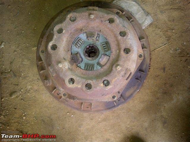
In this picture one see the clutch plate exposed as the cover is removed
Automobile Technologies of the Past - A Revisit-fluid-drive-1.jpg

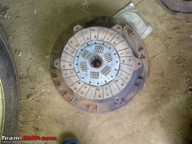
With the clutch plate removed one see the Runner clearly
Automobile Technologies of the Past - A Revisit-fluid-drive-2.jpg

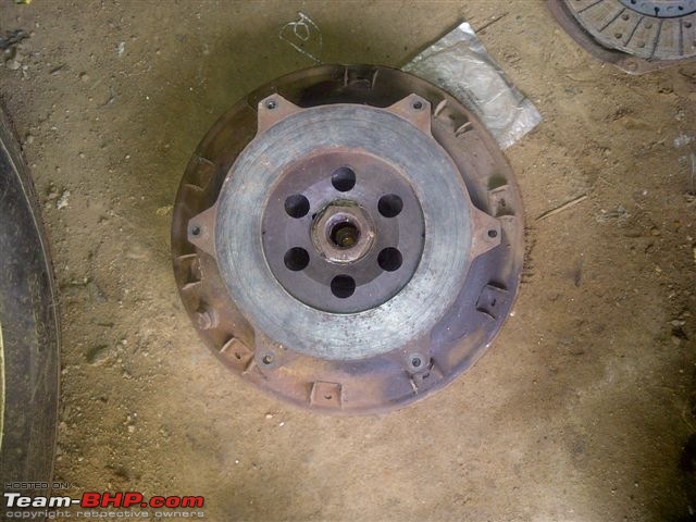
Here one sees how big the Fluid Flywheel actually is. The size of this results in the housing to be larger than ususal
Automobile Technologies of the Past - A Revisit-fluid-drive-3.jpg

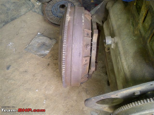
The drain plug for the 10 grade oil. The oil is supposed to be for life.
Automobile Technologies of the Past - A Revisit-fluid-drive-5.jpg

The front part which attached to the crank shaft and is called driver
Automobile Technologies of the Past - A Revisit-fluid-drive-4.jpg


I do hope that the stalwarts in the Forum will share their knowledge with pictures so that every one can understand better.

Cheers

KPS
KPS is offline   (8) Thanks
Old 18th October 2011, 08:40   #2
KPS
Distinguished - BHPian
 
KPS's Avatar
 
Join Date: Nov 2009
Location: Bangalore
Posts: 2,756
Thanked: 11,502 Times
Re:Transvere Engine in the Mini

Here is a design which is still in vogue with some modifications though. I am discussing on the Transverse Mounted Engine.

In 1959 the Mini was the first car to have the Transverse Mounted Engine with front wheel drive.

More details are found in the following thread
http://en.wikipedia.org/wiki/Mini

The above link is quoted below for easy reference

Quote:
The Mini is a small car that was made by the British Motor Corporation (BMC) and its successors from 1959 until 2000. The original is considered a British icon of the 1960s,and its space-saving front-wheel-drive layout (which allowed 80% of the area of the car's floorpan to be used for passengers and luggage) influenced a generation of car-makers. The vehicle is in some ways considered the British equivalent to its German contemporary, the Volkswagen Beetle, which enjoyed similar popularity in North America. In 1999 the Mini was voted the second most influential car of the 20th century, behind the Ford Model T.
Quote:
The Mini used a conventional BMC A-Series four-cylinder water-cooled engine, but departed from tradition by mounting it transversely, with the engine-oil-lubricated, four-speed transmission in the sump, and by employing front-wheel drive. Almost all small front-wheel-drive cars developed since have used a similar configuration, except with the transmission usually separately enclosed rather than using the engine oil. The radiator was mounted at the left side of the car so that the engine-mounted fan could be retained, but with reversed pitch so that it blew air into the natural low pressure area under the front wing. This location saved precious vehicle length, but had the disadvantage of feeding the radiator with air that had been heated by passing over the engine. It also exposed the entire ignition system to the direct ingress of rainwater through the grille.
Here are our pictures of the 1959 Morris Mini Estate Woody we owned at some point. This car fortunately is still in Bangalore and in very good hands

The picture of the car during one of the Bangalore rallies in 2001
Automobile Technologies of the Past - A Revisit-dsc00982.jpg

The engine bay is seen here. Note the Transverse Mounted engine. Note the position of the radiator on the right side. Cooling was not one of its strengths. The engine and gear box shared the same oil hence the gear box had to be handled carefully.
Name:  DSC00983.JPG
Views: 7164
Size:  69.0 KB

Cheers

KPS

Last edited by Rehaan : 23rd December 2011 at 10:57. Reason: Adding direct link
KPS is offline   (2) Thanks
Old 22nd October 2011, 12:35   #3
Senior - BHPian
 
harit's Avatar
 
Join Date: Nov 2008
Location: Mumbai
Posts: 4,033
Thanked: 3,281 Times
re: Automobile Technologies of the Past - A Revisit

Two more systems which come to my mind were the Magnetto and the Autovac. The first gave sparks to engines, later replaced by the distributor. The second pumped fuel to the engine using a vacuum technique, now w e have fuel pumps. Both need care to repair and maintain.

Cheers harit
harit is offline  
Old 22nd October 2011, 13:47   #4
BHPian
 
mbz180's Avatar
 
Join Date: Jan 2010
Location: Kolkata
Posts: 893
Thanked: 1,023 Times
re: Automobile Technologies of the Past - A Revisit

In the early years of the 'Motor Car' (short for Motorized Carriage), Georges Bouton, Albert Di-Dion and Charles Trepardoux invented what came to be known as the 'De-Dion' axle.

This was a revolutionary suspension set up for the rear axle, which made the 2 sides of the axle move independently from each other. This was at a time when most if not all cars used a solid, fixed beam axle, something that continued in a lot of marques till decades later. Their car company, which was initially known as De-Dion et Trepardoux and later as De-Dion Bouton, used this technology right to the end of their company's car production.

More than a 100 years later, the Di-Dion axle is considered as one of the better independent suspension set ups.

Two pics of my 1958 Mercedes Benz 180 A shows this set up, which was used in all the Ponton model Mercs and those that followed.


Best Regards
Prithvi
Attached Thumbnails
Automobile Technologies of the Past - A Revisit-rdiff.jpg  

Automobile Technologies of the Past - A Revisit-fdiff.jpg  

mbz180 is offline   (5) Thanks
Old 8th November 2011, 16:03   #5
KPS
Distinguished - BHPian
 
KPS's Avatar
 
Join Date: Nov 2009
Location: Bangalore
Posts: 2,756
Thanked: 11,502 Times
re: Automobile Technologies of the Past - A Revisit

In the era of carburettors there were basically three kinds, namely updraft, side draft and down draft carburettors.

The updraft carb are those where the air enters from below the carb and exits from the top. The diagram below gives an easy explanations
Name:  FUELF14.gif
Views: 7350
Size:  21.5 KB

The advantage of this system is that engine never got flooded as the extra fuel would fall out of the carb as apposed to into the intake manifold. However this system used up a lot of space.

Here are pictures from our Plymouth showing an updraft carb. The air intake from the bottom can be clearly seen

Automobile Technologies of the Past - A Revisit-img2011110600115.jpg

Automobile Technologies of the Past - A Revisit-img2011110600116.jpg

Cheers

KPS
KPS is offline   (4) Thanks
Old 8th November 2011, 16:39   #6
Senior - BHPian
 
wasif's Avatar
 
Join Date: Jan 2009
Location: Abu Dhabi (for now)
Posts: 2,957
Thanked: 414 Times
re: Automobile Technologies of the Past - A Revisit

What is that contraption affixed to teh intake manifold justabove and to the carb ?

Is it some kind of a brake booster ?
wasif is offline  
Old 8th November 2011, 19:25   #7
KPS
Distinguished - BHPian
 
KPS's Avatar
 
Join Date: Nov 2009
Location: Bangalore
Posts: 2,756
Thanked: 11,502 Times
re: Automobile Technologies of the Past - A Revisit

Quote:
Originally Posted by wasif View Post
What is that contraption affixed to teh intake manifold justabove and to the carb ?
Is it some kind of a brake booster ?
That actually is an automatic clutch control as explained beautifully by vintageman


Quote:
Hello KPS ,
The automatic clutch control mechanism is mounted on the engine and connected to the clutch operating lever. It is operated by the vaccum in the intake manifold. The control plunger activated by the button on the dash activates / deactivates the system.

The unit permits the automatic disengagement of the clutch when the accelerator is completely released ; the clutch is again engaged when the accelerator is depressed. Thus permitting gear changes without using the clutch pedal.
Regards
Cheers
KPS is offline  
Old 8th November 2011, 21:24   #8
Senior - BHPian
 
Join Date: Aug 2005
Location: BOMBAY
Posts: 1,821
Thanked: 2,005 Times

Quote:
Originally Posted by KPS

That actually is an automatic clutch control as explained beautifully by vintageman

Cheers
Similar was seen in a Chrysler airflow 1947 . The automatic clutch control. It really makes he drive fantastic on a straight.
kasli is offline  
Old 15th November 2011, 18:07   #9
KPS
Distinguished - BHPian
 
KPS's Avatar
 
Join Date: Nov 2009
Location: Bangalore
Posts: 2,756
Thanked: 11,502 Times
re: Automobile Technologies of the Past - A Revisit

Braking in cars is normally done using friction brakes. Typically all of us are used to seeing either drum brakes or disc brakes. The older cars sported Band Brakes, some as the primary braking and others as secondary braking

Wiki explains Band Brakes as follows

Quote:
A band brake is a primary or secondary brake, consisting of a band of friction material that tightens concentrically around a cylindrical piece of equipment to either prevent it from rotating (a static or "holding" brake), or to slow it (a dynamic brake).
Here are pictures of a band brake for a better understanding.

This is the hand brake set up in a Chrysler Windsor featuring a band brake in its secondary braking mode
Automobile Technologies of the Past - A Revisit-t-brake.jpg
Automobile Technologies of the Past - A Revisit-t-brake-1.jpg

The next set is from a 1928 Willis Overland where the Band Brake was a primary brake

Automobile Technologies of the Past - A Revisit-clasp-brake-1.jpg
Automobile Technologies of the Past - A Revisit-clasp-brake-2.jpg
Automobile Technologies of the Past - A Revisit-clasp-brake-3.jpg

Cheers

KPS
KPS is offline   (2) Thanks
Old 15th November 2011, 18:20   #10
Senior - BHPian
 
wasif's Avatar
 
Join Date: Jan 2009
Location: Abu Dhabi (for now)
Posts: 2,957
Thanked: 414 Times
re: Automobile Technologies of the Past - A Revisit

The earliest form of braking was achieved by the externally contracting brake bands as posted by you.

Then things went internal to keep the surfaces clean and make thinsg last a buit longer.

And now its again external contracting disc brakes ....wheel has come full circle
wasif is offline  
Old 15th November 2011, 19:04   #11
Senior - BHPian
 
manishalive's Avatar
 
Join Date: Apr 2009
Location: Bangalore
Posts: 2,514
Thanked: 1,079 Times
re: Automobile Technologies of the Past - A Revisit

Band brakes were also used for hand brakes in Fiat and other vehicles where the drun was mounted on the gearbox output shaft.
manishalive is offline  
Old 27th November 2011, 20:35   #12
KPS
Distinguished - BHPian
 
KPS's Avatar
 
Join Date: Nov 2009
Location: Bangalore
Posts: 2,756
Thanked: 11,502 Times
re: Automobile Technologies of the Past - A Revisit

Exhaust Control Heat Control Valve is a important system in very cold climate. When the engine's cold it directs most of the exhaust to the bottom of the intake manifold and helps to warm it up. The shaft has a valve, flapper inside that opens and closes as the engine warms up. As the engine warms up it opens and directs the exhaust to the exhaust manifold directly.

This systems helps the engine warm up in very cold places.

Here are the pictures taken taken from 1954 Dodge which I am restoring.

Automobile Technologies of the Past - A Revisit-img2011111900137.jpg

Automobile Technologies of the Past - A Revisit-img2011111900160.jpg

Cheers

KPS
KPS is offline   (5) Thanks
Old 20th December 2011, 11:19   #13
KPS
Distinguished - BHPian
 
KPS's Avatar
 
Join Date: Nov 2009
Location: Bangalore
Posts: 2,756
Thanked: 11,502 Times
re: Automobile Technologies of the Past - A Revisit

Trafficators always fascinates us and the only risk we carry when we demonstrate is that the person seeing it for the first time tends to fold it back resulting in it going kaput!

Wiki defines as below
Quote:
Trafficators are semaphore signals which, when operated, protrude from the bodywork of a motor vehicle to indicate its intention to turn in the direction indicated by the pointing signal. Trafficators are often located at the door pillar.
Here are pictures taken from a Citroen showing trafficator in the open position (please note that the light is not working)
Automobile Technologies of the Past - A Revisit-cit-trafficator.jpg

The next picture is the trafficator switch in a Citroen. Other British cars mostly had it on the steering wheel.
Automobile Technologies of the Past - A Revisit-cit-trafficator-swtich.jpg

Cheers

KPS
KPS is offline   (2) Thanks
Old 22nd December 2011, 14:26   #14
KPS
Distinguished - BHPian
 
KPS's Avatar
 
Join Date: Nov 2009
Location: Bangalore
Posts: 2,756
Thanked: 11,502 Times
re: Automobile Technologies of the Past - A Revisit

We are used to using the dip sticks to check the engine oil level. In the old days there was huge space in the engine bays and access to the engine was from both sides. Now a days with transverse mounted engines and limited space, the dip sticks are must for checking engine oil levels.

Here is a unique system in a 1947-48 Citroen which has no dip stick but an oil level indicator. The picture is courtesy of Adkol's car.

Automobile Technologies of the Past - A Revisit-cit-oil-level-indicator.jpg

Cheers

KPS
KPS is offline   (3) Thanks
Old 26th December 2011, 14:17   #15
KPS
Distinguished - BHPian
 
KPS's Avatar
 
Join Date: Nov 2009
Location: Bangalore
Posts: 2,756
Thanked: 11,502 Times
re: Automobile Technologies of the Past - A Revisit

The Seven Passenger/Seater Vintage and Classic cars always have a Wow factor as these cars usually had top of the line trim levels. Secondly seven passenger cars were more expensive and thus their owners were rich people and normally there would be some history with the owner and car.

Here is picture of the rear seating in typically arrangement of a seven passenger seating. Thus 2 in the front, 2 in the middle and 3 in the rear could be accommodated in such a seating pattern. There are some minor variations like in some cases the additional seats come from the back rest of the front seats.

Automobile Technologies of the Past - A Revisit-dsc02959.jpg

Cheers

KPS
KPS is offline   (1) Thanks
Reply

Most Viewed


Copyright ©2000 - 2024, Team-BHP.com
Proudly powered by E2E Networks