News
DIY Installation: How I automated the 'courtesy honk' in my car


I have noticed that almost 98% of my horn usage is actually to make very quick and short chirps.
BHPian clevermax recently shared this with other enthusiasts.
This thread will detail how I automated the "Courtesy Honk" or the 'Friendly Honk' in my car. I got the idea from my daughter - she watched a YouTube video demonstrating the courtesy honk, and she asked me if I can implement it.
So this is my own implementation of the courtesy honk. Wrote my own microcontroller code and did my own electronic circuit design.
First of all, what is a 'Courtesy Honk'?
Going by the western definition of it, a courtesy honk is used to get the attention of other drivers in a non-emergency scenario. It's two quick chirps of the horn that is friendly sounding, and not very irritating as a longer or continuous honk.
In the Indian context, this has more use cases for sure. For example, you're cruising on a highway and you sense that the two-wheeler guy in the front is showing symptoms of an unannounced right turn or a lane change. You can then trigger this in order to grab the attention of the rider with two quick chirps instead of a longer honk.
Why Automate it?
Two reasons.
- First reason: One can always press the horn pad two times in succession with a very short interval in between. However, you won't be able to consistently reproduce the pattern all the time. Sometimes, you will end up honking a little longer and that will sound irritating to other road users. The horn pad is a bit 'hard-to-press' in many cars and this makes it nearly impossible to do a very consistent courtesy honk all the time.
- Second reason: If I can automate it, then why not?
I do understand that good driving manners include extremely minimal usage of the horn. But on our roads, sometimes a honk can save a life - this can be an absent-minded rider in front of you taking a right turn without indicators, or someone who is crossing the road without checking if there are oncoming vehicles. The courtesy honk will grab their attention but at the same time, it won't be very irritating. I have noticed that almost 98% of my horn usage is actually to make very quick and short chirps.
There may be commercially off-the-shelf horn solutions out there with different types of horn patterns and sounds, but I did this for the fun and satisfaction that a DIY project can give. I hope the DIY'ers on the forum will find it interesting and useful.
Disclaimer: It is over-engineered for the need! The upside is that there is a microcontroller inside the car now, which can be used for a few other purposes as well, in the future.
When I started thinking about a solution, the first thing that struck my mind was the Arduino which was lying around, unused. So I decided to use it as the controller. As I mentioned in the first post, will this be an over-engineered solution for the need? Of course yes. Will it be fun? Yes!
The design considerations were:
- The design should not have any impact on the existing horn functionality. When the steering horn pad is pressed, the horn should sound just like before.
- The design should not introduce any new points of failure for the existing horn circuitry.
- It should not drain the car's battery when the car is parked.
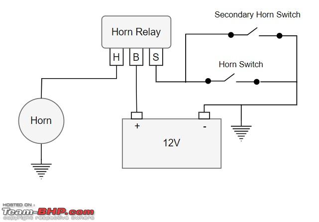
This shows a typical horn circuit.

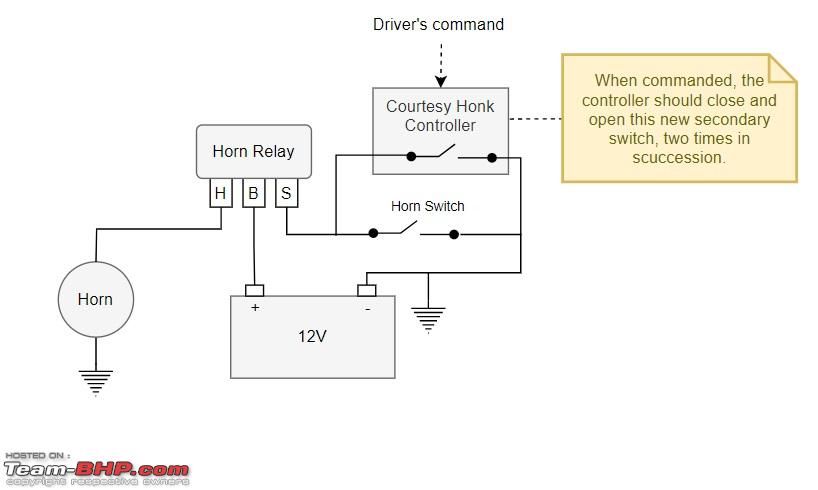
If you had to have a second horn switch for the same horn, without impacting the existing system, this is how you could achieve it.
From this, it is very easy to visualize the high-level design of the required system. We just need to visualize a controller controlling the secondary switch, that can produce any pattern of honking as programmed. In this particular case, the pattern will be the courtesy honk pattern - two quick chirps.
This stage has two parts.
- Microcontroller programming
- Driver circuit design for driving the horn's relay
Microcontroller programming
The microcontroller board that I had (Arduino UNO) has several GPIO pins, but for this project, we only need to use two pins. One of the pins is to be set as an input pin, where the command from the driver's command button (a tactile switch) is to be sensed. The other pin will be a digital out pin, which should be used to drive the horn's relay.
Since the button press has to be sensed almost instantaneously, I decided to make use of the ISR (Interrupt Service Routine) capability of the Arduino. ISR will trigger a hardware interrupt to stop whatever the microcontroller is doing, to process the command button press instantly. This is essential since the horn should instantly when you press it.
In order to develop the code, I made a PoC circuitry using a breadboard, where the digital output pin will directly operate an active buzzer. This gave me the platform to play around with while coding the microcontroller.

Here's the final source code, which underwent a few iterations to perfect the delays and the beep timings.
Here is a video of how the buzzer circuit worked after this stage.
The Horn Relay Driver Circuit
Now, it was time to look at how I will hook up the microcontroller with the car's horn relay system. The car's electricals work with a 12 volts system and that includes the horn's relay as well. The Arduino GPIO has a max output voltage of 5 volts. Moreover, the horn's relay is ground-based, and it is not expecting a voltage to drive it. Instead, it needs to be grounded to trigger the horn. The relay consumed about 300-350 mA of current when the horn is triggered, so the project needed a grounding mechanism that could handle at least 500mA of current.
This called for designing a driver circuit, which will ground the horns relay with the input from the microcontroller. Using another relay to drive the horn's relay was out of the question since I didn't want to use a relay to drive another relay. The simplest circuit I could think of was to use a capable PNP transistor that could effectively ground the line when its base is grounded. I also wanted to electrically isolate the microcontroller's GPIO from the driver circuitry, so I decided to use a combination of an optocoupler and a transistor.
The idea was to drive the optocoupler from the output line of the Arduino, which in turn will trigger the transistor which will 'ground' the horn's relay line.
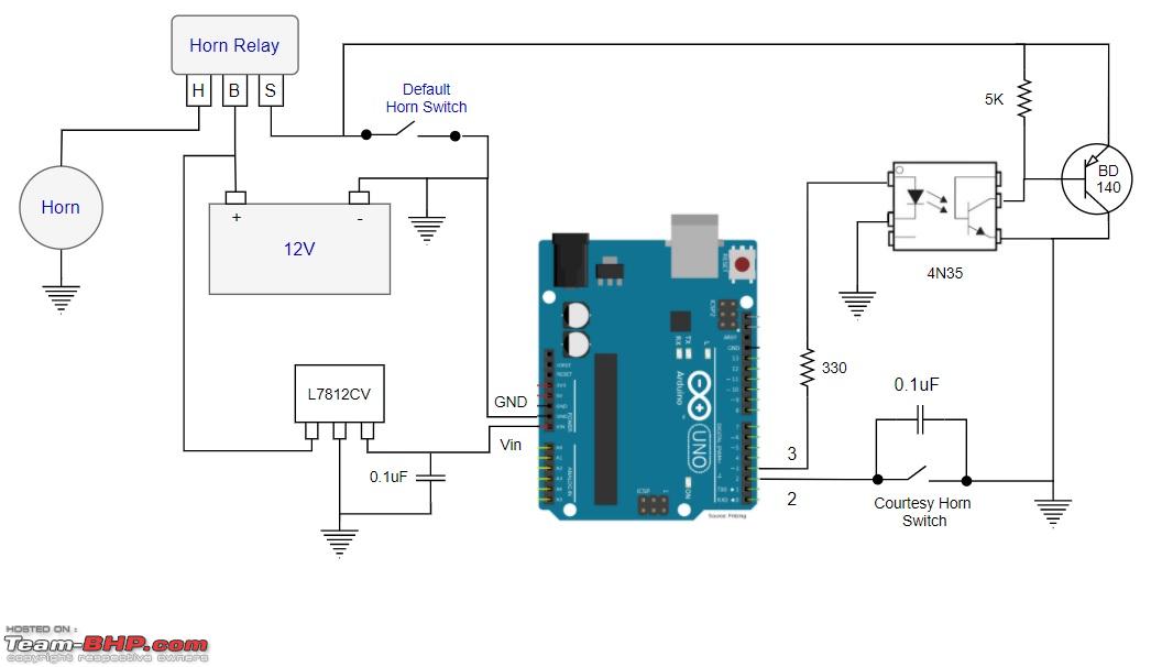
The other question was on powering the Arduino. The documentation says that it can work with a 12v input on its Vin pin, however, the car's battery voltage will go up to more than 14 volts while the engine is running. So I decided to use a voltage regulator to limit the maximum input voltage to the Arduino to 12 volts.
After considering all these factors, here is the schematic of the final circuit that I came up with. Of course, this required a few iterations on the breadboard to iron out a couple of bugs, including the unpredictable behaviour from the tactile switch which resulted in an unwanted double triggering. The capacitor placed in parallel with the tactile switch solved this issue perfectly.
A video of the breadboard test.
Continue reading BHPian clevermax's DIY process for more insights and information.
- Tags:
- Indian
- Member Content
- DIY
- car horn
Find Car News
Just News


About Us


Buy & Sell
USED CARS