News
DIY: Upgraded the Body Control Module (BCM) on my VW Polo 1.0 TSI


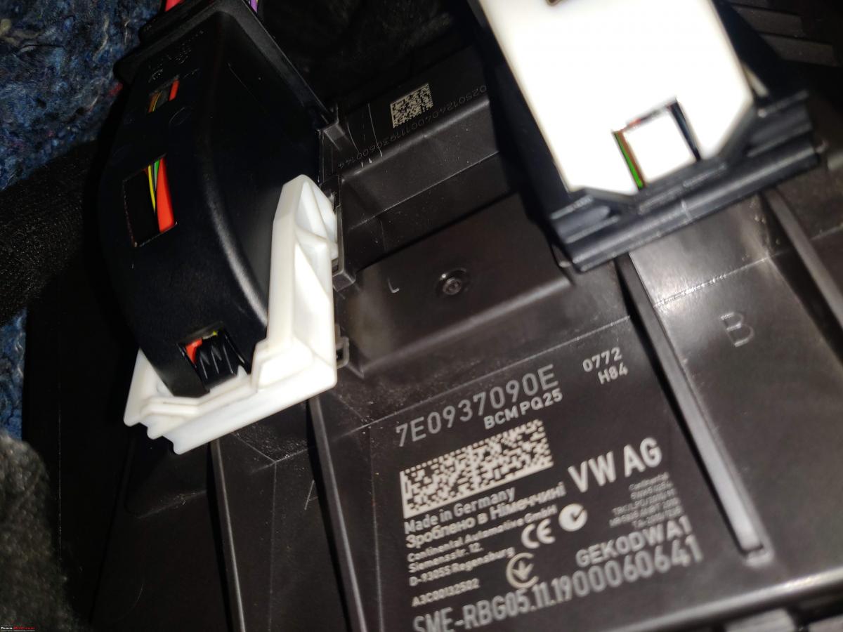
I cross-checked and labelled wiring harness to ensure I would be touching the right wires. Even if you have been given instructions, it's always better to do your own homework.
BHPian fluidicjoy recently shared this with other enthusiasts.
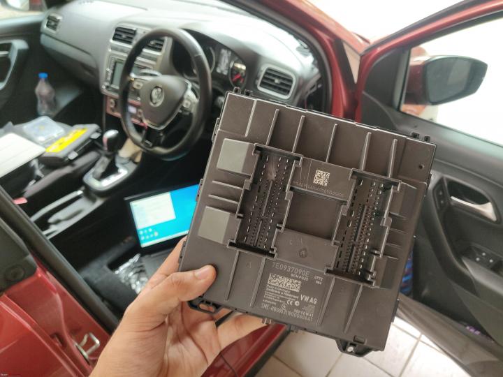
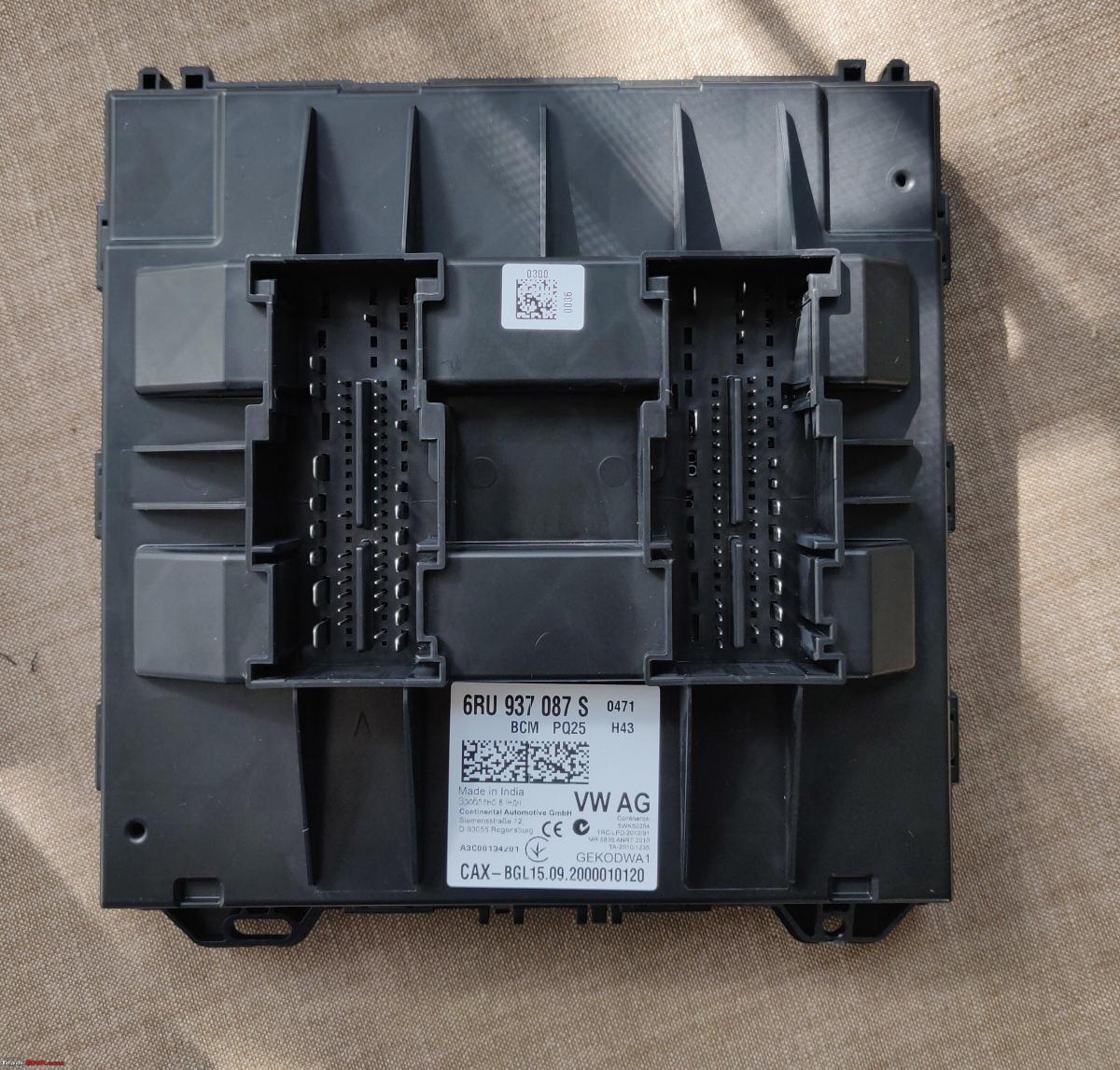
The BCM on my Highline+ 1.0 TSI Automatic Polo was a BCM 6R0937087S and to be fair, the 87S BCM supports quite a lot of features to be honest. Other than Automatic Headlights and Factory style Coming Home and Leaving Home headlights, there doesn’t seem to be a strong reason to necessitate a BCM upgrade. The BCM on what is perhaps this last lot of PQ25 Polo and Vento cars is Made in India by Continental:
The swap from BCM 087S to 7E0937090E for Polo Highline+ guys is not a straight swap and needs quite a few wiring changes. So what’s fundamentally different between the two BCMs is how they handle the power and control signals for the headlight terminals. In the present Polo configuration, the headlights are controlled by the light switch. In the newer BCM, the headlights are BCM Controlled. This ability of the lights being BCM controlled is what allows the car to enable Automatic Lights based on the input from the Rain and Light Sensor.
The second main difference is that the BCM Max runs on an independent CAN line. The Powertrain CAN line runs the Engine, Gearbox control units, Optical Parking Sensor (OPS) module etc, while the Radio and Auto-AC runs on CAN Convenience. To the best of my knowledge, quite a few Skoda Rapids and the Vento Highline+ come with 7E0 937 089 D which is not exactly BCM Max, but is a high version of the BCM which is wired from the factory to have Headlight Control. Swapping to BCM Max for these particular cars could be a fairly straight swap, but only experienced folks can tell if there’s any more changes that need to be done:

Pros of a BCM Upgrade (From My Point Of View, A Polo Guy With A Hunger for Upgrades):
- Factory-level functionality of OEM Headlight Upgrade options.
- Automatic Headlights based on factory fit Rain and Light Sensor (RLS).
- Coming Home and Leaving Home Lights without any aftermarket Chinese module.
- Factory support for OEM LED License Plate Lights.
- Supports Interior Brightness Illumination Dimmer Switch
- Opens door to a host of next generation features like Direct TPMS, Blindspot Monitoring, Fatigue Detection, Keyless Entry to name a few.
Cons:
- Definitely a warranty killer for the Polo since it involves rerouting quite a lot of factory wires which cannot be achieved without wire cutting and relay modification.
- Time consuming.
- Expensive affair.
- Limited support available if things go wrong.
- Not a simple retrofit kit unlike majority of plug and plug accessories available.
Tools I used:
- Wire Strippers.
- Electrical Automotive Terminal Removal Tools.
- Plastic Trim Removal Tools.
- Multimeter
- Automotive Tape.
- VCDS.

I won’t be covering the entire upgrade since it has already been covered by BHPian Graaja a few years back when he installed OEM Bi-Xenon Headlights on his Polo. You can read about it here. Additionally, you might also want to refer to this nice thread on a BCM upgrade by Moderator Gannu for some basic fundamentals about a BCM change, but this thread will not be a detailed guide to wiring modification to the BCM loom.
I’ll try and share new insights with respect to my installation. Unlike many others who have attempted a similar installation in the past, I must say that the task was slightly shorter for me since the recent Polos do come with a factory fitted Rain and Light Sensor, so I did not have to worry about fitting and wiring that in.
Pre-Task Research:
So, before I started, I gathered all of my tools and put them in a tray for easy access. I took photographs of the wiring harnesses and labelled them on my iPad to ensure I knew which wire was to go in where. On many instances, I was liberally using the iPad's camera and relying solely on the iPad screen, and it was similar to an endoscopic surgery:
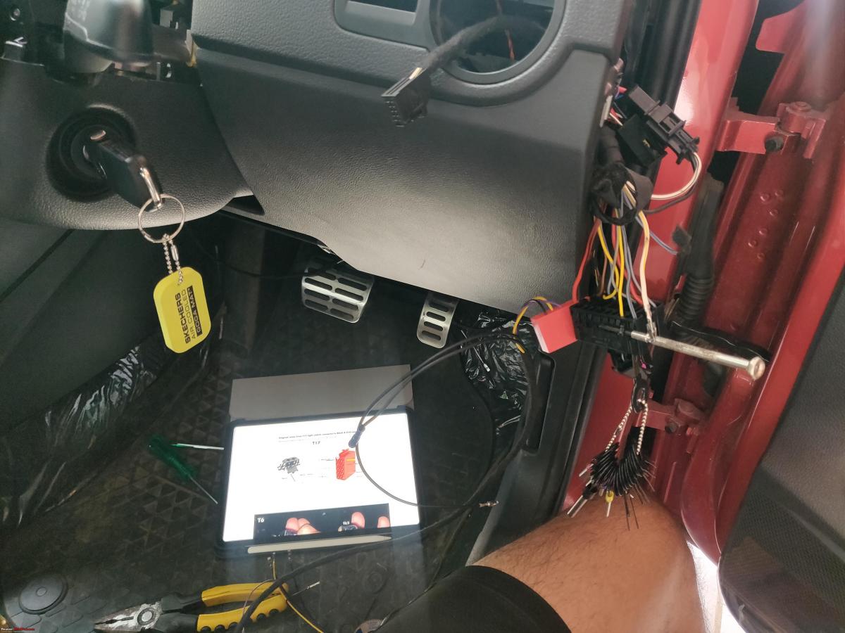
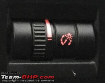
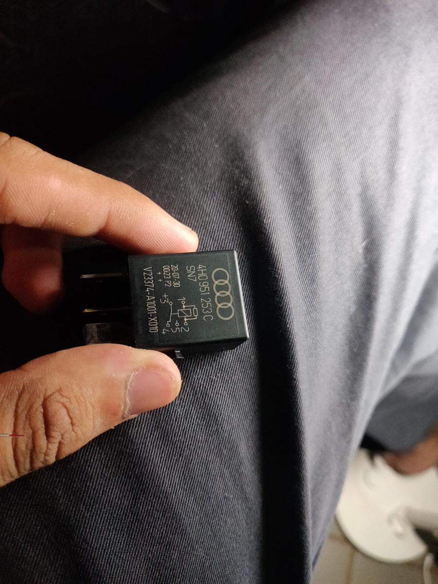
I cross-checked and labelled wiring harness to ensure I would be touching the right wires. Even if you have been given instructions, it's always better to do your own homework and be prepared for potential surprises. I printed out a list of my Official Fusebox from the factory and labelled all relevant Fuses for the Headlights, and Side-Lights. Next, it was important to identify the key relays on my car and engine:

Next I grouped the tasks and allotted about 3 hours each of my day to complete that task. I’d typically start working around 4PM and end around 7:30PM when I was called for family dinner. This was perhaps not the best idea, but with the help of my phone and iPad flashlights, I managed to complete the task, even at these odd hours. Since I was moving to the US for higher education, and I was set to leave in less than 2 weeks, I genuinely had limited time to complete what I had set out to do, and the fact that shipping logistics were not on my side, was just another twist to the tale.
- Headlight Switch Wiring.
- Fusebox Wiring.
- BCM Connector Wiring.
- License Plate Lights Wiring.
Each of these sub-groups had a few challenges, which were overcome with the right tools and a little bit of grit and spirit. Quite a few times, I felt stupid, felt like giving up, but I was in too deep, and there was no going back, and I kept going, and finally, it was done.
Getting Started:
Swapping the BCM per se, does not need too much effort. In fact, since I have fairly long hands, I could remove the stock BCM with my left hand by sitting on the driver sill and stretching my left hand. However, it is not possible to easily make wiring changes in the BCM connector or the fusebox without taking the dashboard out.
Now taking the entire dashboard out on a brand new car, less than a year old, was practically out of question, and so I had to do it the way most other men had. By moving trims, seats and as many trims as possible to create some more working room. Frankly, the difficulty of this BCM Max wiring would be halved if the dashboard was removed. It would have been a piece of cake to properly route wires, de-pin connectors, crimp wires and do it in the neatest possible way. However, this was not something I had ever considered and so I had to just keep going on the only feasible route I knew:
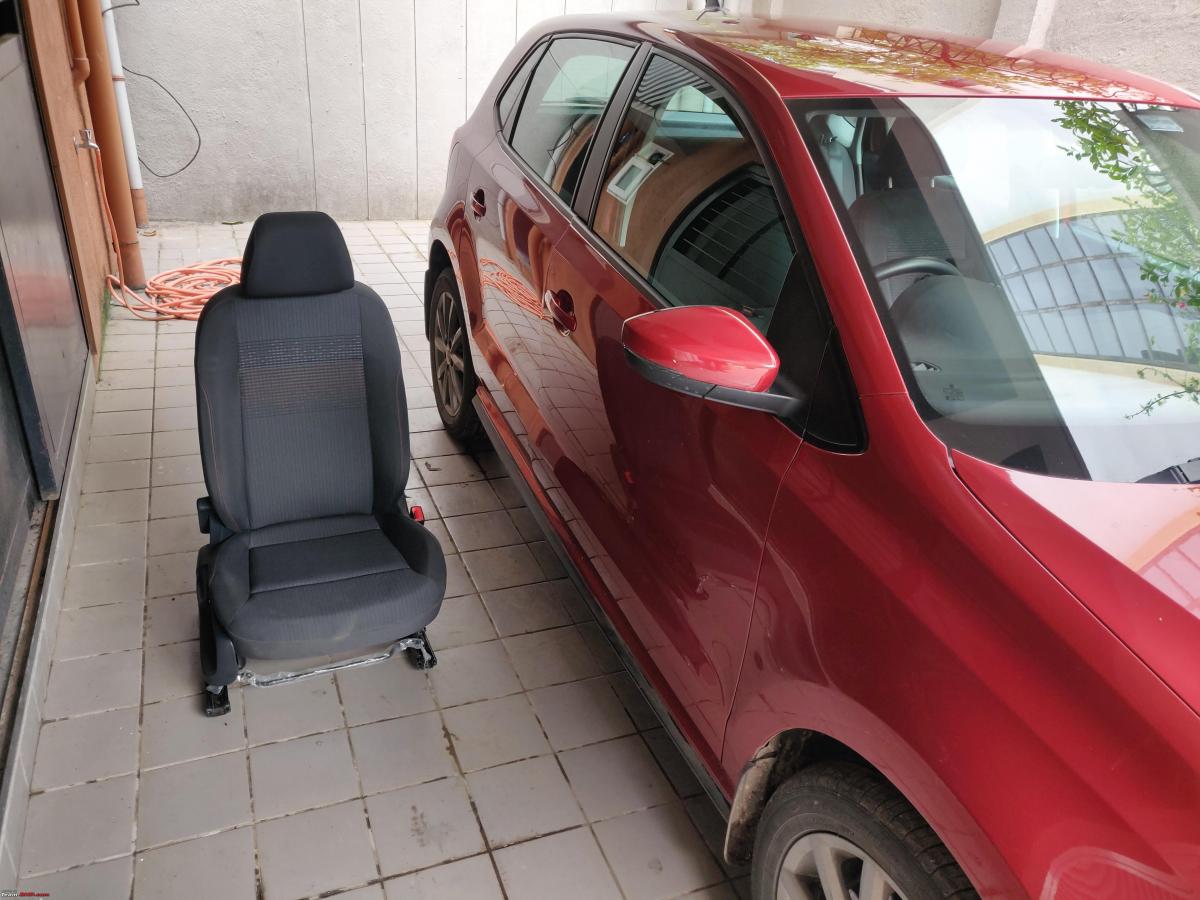
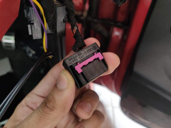
So using a Spline bit (an M10 if I remember correctly), I freed the four bolts which bolt the driver seat down to the car’s frame. There’s a Green electrical connector, presumably the Seat Belt Buckle switch, going to the Airbag Control Unit under the seat which needs to be disconnected before the seat can be lifted out of the vehicle. The Connector has a small plastic tab on the side, so make sure you release that before trying to yank out the connectors apart:

I estimate the weight of the seat to be almost 10–15kgs, give or take a few kilos. With the seat out of the way, there’s now plenty of space to sleep along the driver side, like many men have in the past. However, this space is still not roomy enough to work on wires, but we have to make do with whatever is available:

Instrument Cluster Wiring:
The cluster houses one of the most important CAN lines, the CAN-Powertrain and BCM Max works with a dedicated twisted CAN-pair which needs to be connected in the T32 Cluster connector. This connector is where the Brake Wear Sensor and Windshield Washer Fluid sensor pins would need to be inserted before these features are coded in the cluster:
I had some trouble with de-pinning one of these cluster pins since it was touched during my OPS installation. To my misfortune, the crimp on one of the CAN pin broke entirely and got stuck in the connector. I tried a lot, but couldn’t manage to unpin it. This is what happens if you end up using cheap wires and badly crimped connectors. You might just get stuck when you need them to be reliable the most:
This has never happened to me on any other factory wire during de-pinning which makes me certain it was the quality of the cheap wire crimp which gave up prematurely. I set this task aside, and attempted it the next day with a fresh approach and it was thankfully done. This time, I pushed the terminal from the front and pushed it out. Too much force can damage the plastic locking points and cause loose connections at the cluster end, so be careful whilst prying stuck crimps.
Headlight and Dimmer Switch:
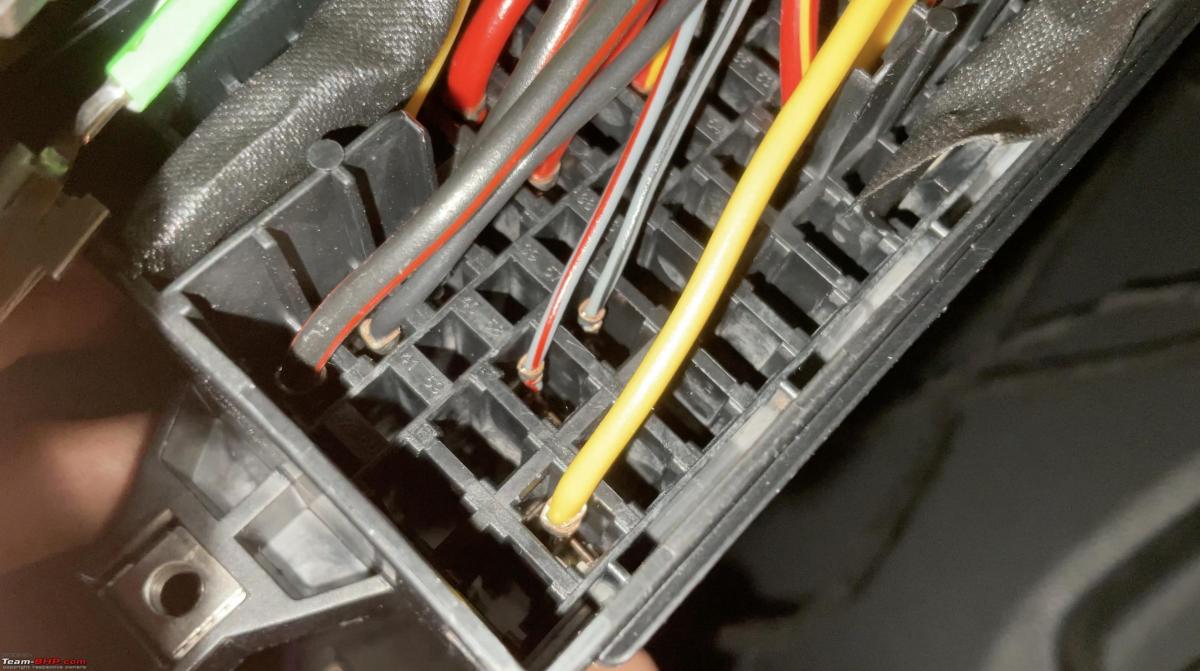
The Polo comes with a 17 pin headlight switch. We de-pin this headlight switch by lifting a small tab on the top and inserting the appropriate terminal removal tool:

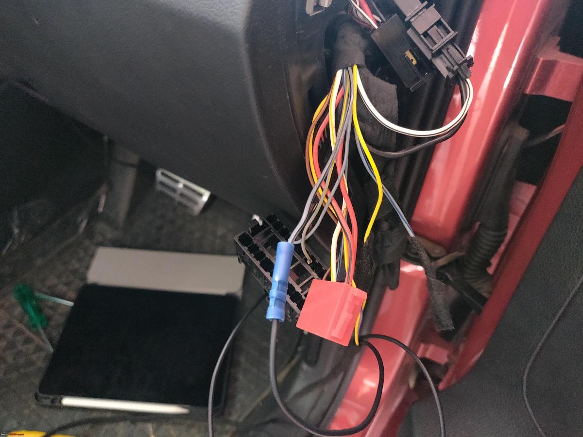
Some wires will now be isolated since their connected relays will be shorted in the eventual installation. T17/9 is the wire for the Rear Fog-Lamp and it is now driven by the BCM and so it will be cut and crimped. The sidelights (Fuses 57 and 58) are protected by a fuse on the Polo Highline, so they are isolated as well. Isolated wires were taped with few rounds of Tessa tape. T17/17 (Grey-Blue) is the pin for the interior lighting of switches and buttons and is referred to as Terminal 58d. If you’re installing an interior illumination or ambient lighting accessory, then it can be tapped from this point. The wiring changes were introduced into a secondary connector, which was red in colour:

Lamp Diagnostics for License Plate lights was left Unchecked on my Stock Car. This is why retrofitting LED License Plate lights on a Polo do not leave an error at present. However, BCM Max is designed to power OEM LED License Plate lights and if not wired, they will leave a Bulb out error. Hence, T17/16, which is a thicker Grey-Blue wire which is the stock wire for the rear Number Plate lights. It must be isolated as well. We run a fresh wire from T73b/7 to the License Plate light wiring joint in the rear of the car, in the boot trim on the Polo 6R:

I also installed the Dimmer Switch which is now BCM Controlled as well. This switch was on my To-Do even before I was considering BCM Max and has been installed and documented by a few BHPians already. Here is the Dimmer Switch connector which I had to insert a few wires:

The dimmer switch comes in a two types. Dimmer with Headlight Range Control and Dimmer without Headlight Range Control. Since I was installing AFS (Automatic Range Control for Headlights), I decided to opt for the later part:
Without BCM Max, the Dimmer does not work as best as it can and if the License Plate Lights are not isolated, then they end up dimming with dimmer switch as well, which should not happen since License Plate Lights are meant to be consistently bright during night drives. There is a simple workaround for this, and that involves isolating the output to this circuit from the fusebox.
After these small changes were made, new wiring and relays were introduced to support the Automatic Headlights:

Some older headlight relays had to be removed and replaced to make the new wiring work:

Fusebox Wiring:
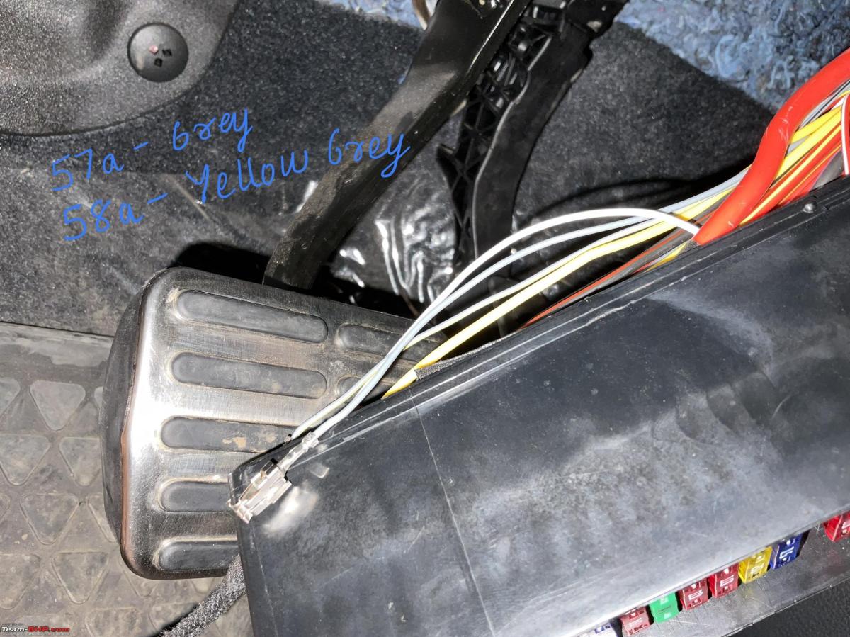
The fusebox is the right place to wire any electrical accessories and this is the place where I’ve crimped and inserted input and outputs of most of my Retrofits like the Flip Camera and the Direct TPMS Unit. To make changes to the fusebox wiring, you need to pull out two pink locking tabs, depending on what row you want to work on, and then insert an appropriate Terminal Removal tool to release the connector crimp out of the fusebox:

Usually folks and accessory shops who don’t want to mess with the fusebox resort to a Fusetap, but for the BCM Max retrofit, there isn’t any room for such shortcuts. Fuses 57 and 58 are for the protection of the Side lights, and these get routed to the BCM on the BCM Max:
There were quite a few blanks on my fusebox and so using some active fuse outputs, I was able to convert them into working fuses for future retrofits:

I have printed my updated Fusebox layout and kept a copy of it in the glovebox for fault-finding and trouble shooting in the future. My regular service advisor has also been informed about the new installations, but the truth is service advisors keep changing. None of the factory fuses have been tapped or touched in any way to split power, and the fusebox looks clean, just the way it should be:

BCM Connector:
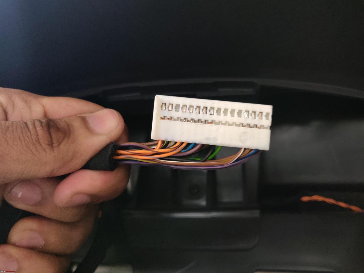
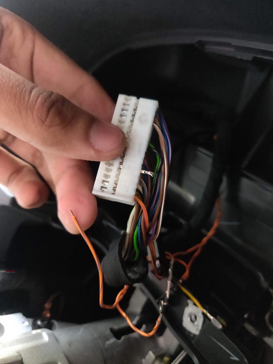
The BCM has two connectors, labelled A and B and they have a distinct sleeve in White and Black connector. Many installers refer to install locations by referring to BCM Connector colours, e.g BCM White Connector, BCM Black Connector. To add or remove wires, we need to release the BCM connector plastic sleeve and then refer to the pin-diagram of the BCM pins. Each BCM connector is like a lego which slides into one another. The wires in the inner rails cannot be accessed without sliding the lego connectors apart:

Using some force, these can slide comfortably, but it’s quite the struggle to put them back together since the harness is tightly taped with automotive tape. Once all the wiring was complete, I plugged the connectors back in and reconnected the battery, and with this step, I thought I was done installing a BCM Max, but there was still a long way to go:
Continue reading on BHPian fluidicjoy's DCM upgrade on his Polo for BHPian comments, insights and more information.
Find Car News
Just News


About Us


Buy & Sell
USED CARS