Team-BHP > 4x4 & Off-Roading > 4x4 Technical


View Poll Results: Poll canceled.
option 1 0 0%
option 2 0 0%
Multiple Choice Poll. Voters: 14. You may not vote on this poll

Reply
  Search this Thread
85,430 views
Old 4th January 2014, 00:54   #136
Senior - BHPian
 
DirtyDan's Avatar
 
Join Date: Jul 2007
Location: Dharamsala, H.P
Posts: 2,072
Thanked: 1,547 Times
Re: Torque generation and distribution

Ha! What an amazing little video that was. Some clever engineers and machinists must have worked many hours fabricating that bench model differential example.

It sort of shows you intuitively why the gears of a differential have to be set at just the right depth to each other, "gear lash".
DirtyDan is offline   (2) Thanks
Old 4th January 2014, 06:50   #137
DKG
Senior - BHPian
 
DKG's Avatar
 
Join Date: Feb 2008
Location: Hyderabad
Posts: 3,711
Thanked: 1,389 Times
Re: Torque generation and distribution

Neat video, but it doesn't explain what happens to the torque in an open differential. Also apart from the torque split being equal the torque disappears too when traction is low at either wheel. It's that fact I was hoping we could discuss.

Typically we would assume that since it's torque that makes the wheel spin, more spin means more torque applied. But in actuality the converse is true. As you rev more in a open diff where one wheel is in the air while speed increases the torque drops. Why? And when it drops where does it go?

Last edited by DKG : 4th January 2014 at 07:07.
DKG is offline  
Old 4th January 2014, 15:45   #138
Team-BHP Support
 
Samurai's Avatar
 
Join Date: Jan 2005
Location: Bangalore/Udupi
Posts: 25,798
Thanked: 45,189 Times
Re: Torque generation and distribution

Alright, going by the silence I suppose it was not a helpful example. In my defense, it is not easy to give human examples of a working open differential. But try this one.

Here is the crude open differential from the video:

Torque generation and distribution-fullscreen-capture-142014-31132-pm.bmp.jpg

Let us represent the 3 crude gears in the above picture with 3 people standing sideways on skateboards in a line, all facing one direction.

Name:  rollers.png
Views: 739
Size:  4.9 KB

Assume all have same weight and all skateboards face same COF. Now, let the middle guy push the other two away using X amount of force on both sides. He will remain in place (net force is zero for middle skateboard), but the guys on the side will move by Y meters. This is similar to how the middle gear doesn't turn when the both the wheels are turning with same speed. The middle guy applied 2X amount of force, both side guys received X amount force to move Y meters. The net force applied to middle gear (to turn) or guy (to move) is zero. Does it make sense so far?

Now remove the skateboard from the left guy, he won't budge anymore. Now let the middle guy apply X amount of force on both sides, like before. What happens? Now the middle guy will move Y meters from left and right guy will move 2Y meters. Compare this to the situation in the video where the left wheel is stopped. It forces the middle gear to rotate, forcing the right wheel to move twice as fast.

Did the middle guy use more force? No, he still used X amount of force in both direction. Similarly, the open differential sends same force in each direction when one wheel is stopped. Just like how only X amount of force was sent to the left guy when he was standing without skateboards.

Well, this is the best I could do to explain it...
Samurai is offline  
Old 4th January 2014, 18:43   #139
DKG
Senior - BHPian
 
DKG's Avatar
 
Join Date: Feb 2008
Location: Hyderabad
Posts: 3,711
Thanked: 1,389 Times
Re: Torque generation and distribution

I am particularly fascinated with the relationship of torque with the speed with which a shaft is rotating. Some form of energy transfer takes place. What exactly happens in this inverse relationship. More than load in the system it's the speed that torque is related to. In gears by varying the speeds of gears in mesh(differing sizes) you enhance or reduce torque. That is fascinating.

Btw in your skateboarders example both side boarders won't move a distance Y as their inertial mass will be different. For the centre boarder to stay unmoved he has to exert equal force on both sides.

Last edited by DKG : 4th January 2014 at 19:11.
DKG is offline  
Old 4th January 2014, 19:12   #140
Team-BHP Support
 
Samurai's Avatar
 
Join Date: Jan 2005
Location: Bangalore/Udupi
Posts: 25,798
Thanked: 45,189 Times
Re: Torque generation and distribution

Quote:
Originally Posted by DKG View Post
Btw in your skateboarders example both side boarders won't move a distance Y as their inertial mass will be different. For the centre boarder to stay unmoved he has to exert equal force on both sides.
Isn't that the assumption I gave? All skateboarders have same weight and same coefficient of friction with the ground. So they will all have same inertia. The center boarder does exert same force on both side.
Samurai is offline  
Old 4th January 2014, 19:20   #141
DKG
Senior - BHPian
 
DKG's Avatar
 
Join Date: Feb 2008
Location: Hyderabad
Posts: 3,711
Thanked: 1,389 Times
Re: Torque generation and distribution

Quote:
Originally Posted by Samurai View Post
Isn't that the assumption I gave? All skateboarders have same weight and same coefficient of friction with the ground.
Sorry missed that. I was thinking about the open diff where regardless of the inertial masses at either end the torque split is still 50:50. The open diff neutralises the imbalance of differing masses at either end. Ultimately it only applies the amount of torque the lower inertial mass requires to spin.

Last edited by DKG : 4th January 2014 at 19:22.
DKG is offline  
Old 4th January 2014, 20:39   #142
DKG
Senior - BHPian
 
DKG's Avatar
 
Join Date: Feb 2008
Location: Hyderabad
Posts: 3,711
Thanked: 1,389 Times
Re: Torque generation and distribution

As torque is applied to the half shafts and the wheels start spinning, the angular momentum of the wheels increases. This would lead to a decrease in the moment of inertia exerted by the wheel which in return affects the torque applied. That is, as the wheel starts spinning torque reduces. So in a open diff where one wheel is on the ground and the other in air as the wheel in air starts to spin faster the torque it requires drops as the moment of its inertia reduces. The more you rev the less torque you apply to the wheels in an open diff.

Last edited by DKG : 4th January 2014 at 20:40.
DKG is offline  
Old 4th January 2014, 20:50   #143
Senior - BHPian
 
Join Date: Jul 2009
Location: Calcutta
Posts: 4,668
Thanked: 6,206 Times
Re: Torque generation and distribution

Quote:
Originally Posted by amit_purohit20 View Post
I agree and please elaborate your point of Slipper clutches and shear pins....
Going by the analogy - If a human is holding onto a shaft tightly, and despite that it starts to turn, the discomfort (skin burns) will cause him to release it in a hurry. -> Shear coupling.
However if he keeps on holding on, exerting the same force -> slipper clutch, a clutch which starts slipping at a preset torque level.

Regards
Sutripta
Sutripta is offline   (1) Thanks
Old 4th January 2014, 23:54   #144
Team-BHP Support
 
Samurai's Avatar
 
Join Date: Jan 2005
Location: Bangalore/Udupi
Posts: 25,798
Thanked: 45,189 Times
Re: Torque generation and distribution

Quote:
Originally Posted by Samurai View Post
Assume all have same weight and all skateboards face same COF.
Alright I made a mistake in this example. Right after I posted it, I realised there was a bug in that example. When all are on wheels, total distance moved was 2Y. When one becomes stationery, the total distance moved became 3Y. Since all three were of same weight, then the work done will be 50% more using the same force. I didn't know how to explain that.

But Sutripta pointed it out offline. He said middle guy has to be weightless.

Correction:
If you look at the video example, both the side gears are attached to a wheel, they have equal load. But the middle wheel is practically weightless. It is merely transmitting the torque, doesn't need to expend any on itself.

So, by making the middle skateboarder weightless, we will only count the distance moved by the right skateboarder, which is 2Y. Sanity restored. This is still a very imperfect example, but I don't know how to improve it.
-------------------------------------------------------------------------
While seeing the video again, I was reminded of one observation I made long back.

What we generally know: In an open differential, the torque split is always 50:50, but speed could be different in different wheels.

So let's take a case where one wheel has no traction. Say that wheel only needs 1Nm to keep rotating. The other wheel needs 50Nm to do the same. In this case we know that the propeller shaft will only deliver 2Nm.

From the video, we know that the middle gear will transfer 1Nm to each side gear. But... the wheel that has traction will not budge, it needs 50Nm to do so. In effect, the entire 2Nm goes to the wheel without traction, that is why it spins as fast compared to before.

So this is my confusion. We say each axle always receives same torque in an open differential. But how do we explain the above situation?

The spider gears are transmitting same amount of the torque to both side gears. But if one side gear (or one axle) is stopped, in effect won't it deliver all the torque to the other side gear?

Last edited by Samurai : 5th January 2014 at 00:05.
Samurai is offline  
Old 5th January 2014, 07:07   #145
DKG
Senior - BHPian
 
DKG's Avatar
 
Join Date: Feb 2008
Location: Hyderabad
Posts: 3,711
Thanked: 1,389 Times
Re: Torque generation and distribution

Sharath there is a torque multiplication at the differential by the pinion and crown wheel so it's not like the prop is supplying the torque quantum needed.

In an open diff just enough torque to make the free wheel spin gets applied. The other half of equal torque would get applied to the stuck wheel but it gets used by the rotating spiders of the crown wheel

Further as the free wheel spins the torque needed drops further and the resultant total torque applied to either of the wheels goes down.

Last edited by DKG : 5th January 2014 at 07:32.
DKG is offline  
Old 5th January 2014, 08:27   #146
Team-BHP Support
 
Samurai's Avatar
 
Join Date: Jan 2005
Location: Bangalore/Udupi
Posts: 25,798
Thanked: 45,189 Times
Re: Torque generation and distribution

Quote:
Originally Posted by DKG View Post
Sharath there is a torque multiplication at the differential by the pinion and crown wheel so it's not like the prop is supplying the torque quantum needed.
Torque multiplication/division keeps happening at every stage. It is not force multiplying. When you double the torque, you also double the time taken. The work done remains the same. It is like voltage step-up/step-down in electricity, it doesn't change the work done. A pair of gears in mechanical engineering, is same as voltage transformer in electrical engineering. Therefore, when we discuss torque distribution, it is better to ignore torque multiplication.

Quote:
Originally Posted by DKG View Post
In an open diff just enough torque to make the free wheel spin gets applied.
You know how I had to abandon the "just enough torque" definition recently, don't you?

Quote:
Originally Posted by DKG View Post
The other half of equal torque would get applied to the stuck wheel but it gets used by the rotating spiders of the crown wheel
What do you mean used by rotating spiders? spiders transmit the torque... but where?

Say two people on roller blades push each other with X amount of force. Both will move Y meters back, assuming everything else is at cet par. What if one of them has his back against a wall? Then only the other will move and by 2Y meters.

Quote:
Originally Posted by DKG View Post
Further as the free wheel spins the torque needed drops further and the resultant total torque applied to either of the wheels goes down.
You are focusing on momentum of the wheel. For understanding torque distribution, it is better to keep the wheels pretty heavy. Once we understand that, then we can take the next step towards momentum.
Samurai is offline  
Old 5th January 2014, 08:50   #147
DKG
Senior - BHPian
 
DKG's Avatar
 
Join Date: Feb 2008
Location: Hyderabad
Posts: 3,711
Thanked: 1,389 Times
Re: Torque generation and distribution

Quote:
Originally Posted by Samurai View Post
it is better to ignore torque multiplication.
Only reason why I mentioned it is because you said the torque at the prop was double the torque to the spinning wheel which it is not in view of the multiplication effect of the crown wheel pinion.

Quote:
You know how I had to abandon the "just enough torque" definition recently, don't you?
Why? The torque applied is only to counter the load the shaft exerts and no more. So it is correct to say just enough torque to counter the moment of inertia. Am I missing something in this?

Quote:
What do you mean used by rotating spiders? spiders transmit the torque... but where?
The spider gears in a differential rotate because of the resistance the slower turning wheel offers. This resistance causes the spider gears attached to the crown wheel to spin about their axis. The torque transmission is on account of the force the crown wheel spiders apply to the half shaft spiders about the axis of the half shafts.

Quote:
You are focusing on momentum of the wheel. For understanding torque distribution, it is better to keep the wheels pretty heavy. Once we understand that, then we can take the next step towards momentum.
Torque and angular momentum have a instrinsic relationship. One generates the other. I feel this is relevant here cause all of us have revved while attempting to get unstuck only to realise it doesn't help. Here's why, all you get is angular momentum in the free wheel but lower resultant torque to the wheel that is stuck.

Forget a case of one wheel in the air and the other stuck bit. Driving on sand in an open diff vehicle unless you apply the throttle gently you end up cutting in and getting stuck. This is because the coefficient of friction drops when the wheels start spinning. With lower coefficient of friction at the contact point the resultant load on the half shafts drop and lesser torque is applied, rendering the vehicle immobile. Driving on sand is all about building momentum and sustaining it and for that you need the torque to reach the wheels. So a light throttle, greater tyre contact patch is your best bet to do this.

Last edited by DKG : 5th January 2014 at 09:03.
DKG is offline  
Old 5th January 2014, 20:01   #148
Team-BHP Support
 
tsk1979's Avatar
 
Join Date: Feb 2005
Location: San Jose, CA
Posts: 23,715
Thanked: 22,756 Times
Re: Torque generation and distribution

So much physics is making me jokey
Two cats are sitting on the roof.
Which one slides off first?
A: One with the smaller Mew
tsk1979 is offline   (7) Thanks
Old 5th January 2014, 22:28   #149
Senior - BHPian
 
Join Date: Jul 2009
Location: Calcutta
Posts: 4,668
Thanked: 6,206 Times
Re: Torque generation and distribution

Quote:
Originally Posted by Samurai View Post
In effect, the entire 2Nm goes to the wheel without traction, that is why it spins as fast compared to before.

So this is my confusion. We say each axle always receives same torque in an open differential. But how do we explain the above situation?

The spider gears are transmitting same amount of the torque to both side gears. But if one side gear (or one axle) is stopped, in effect won't it deliver all the torque to the other side gear?
No, same torque is delivered to both sides.

If we have worked out that the same torque is delivered to both sides, why should there be an exception.

Must also add that I'm not happy with your analogy.

Does everybody agree with the answers to the four cases I had listed sometime back. http://www.team-bhp.com/forum/4x4-te...ml#post3331912
If so, then one can move forward.

Regards
Sutripta
Sutripta is offline  
Old 6th January 2014, 01:39   #150
BHPian
 
amit_purohit20's Avatar
 
Join Date: May 2006
Location: mumbai
Posts: 675
Thanked: 897 Times
Re: Torque generation and distribution

Let me jump in!

To understand Torque and rpm:

Torque = Force X Radius

The above equation doesnot contain rpm so torque and rpm are not dependent directly.

Let us understand the same with another simple analogy.

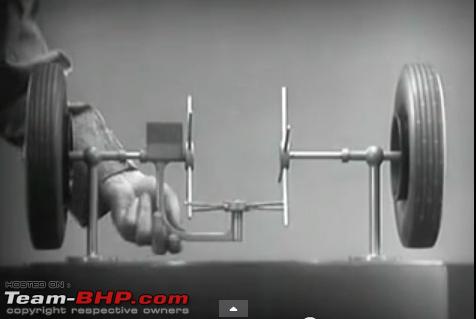
Consider a Block of Wood moving on a Horizontal surface in a straight line at 1 metre/second.(Forget Friction losses, Use KISS principle!) The hand is pushing the block by say 10 N which is causing the block to move at 1 m/second.

Now if you push the block by 20 N but at the same speed ie. 1 m/sec. Will the blocks speed increase? Obviously not.
No because the hand just cannot move beyond 1 m/sec so it cannot cause the block to move beyond 1 m/sec.

Only when the hand which is pushing the block moves at say 2 m/sec then the block would move by 2 m/second.

So here comes the concept of Power to understand rpms. More power means the hand is moving now at higher speed. Here is where the time concept comes into picture.

In an engine when you press the throttle more sudden expansion of gases happen (due to a more bigger bomb exploding over the piston) which not only increase the force on the piston but also increase the rate at which force is applied on the piston.

Coming back to the Open differential.
Torque generation and distribution-differential.jpg
Case1 - When the vehicle is going straight.
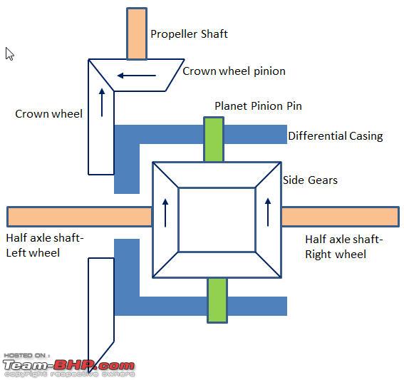
This is how the differential will look like when going straight.
As the Crown pinion (mounted on propeller shaft) turns it rotates the Crown wheel. The Crown wheel rotates the Differential Casing in which the Planet pinions are fixed. As the casing rotates it rotates with these pins. The Planet pinions rotate with these pins not along their own axis but as a system along with the Differential Casing. There is no relative movement between planet pinion and the side gears.

Note that the Planet Pinions are not rotating along their own axis as the tooth forces on this gear are balanced equally on both sides because resistance on the two half shafts or torque on both the side gears is same.

Torque generation and distribution-case1.jpg

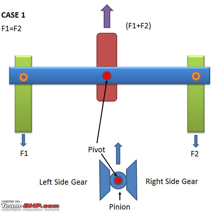
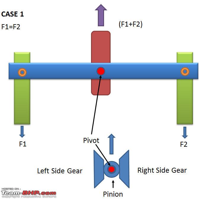
Case 1 when the vehicle is going straight or equal torque resistance on both the wheels.

I have shown the planet pinion pin as red here which was shown in green in the previous diagram.
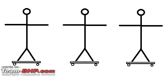
See the bottom configuration. It represents a top view of a open differential.
Please note that I have not drawn here the crown wheel and pinion and also the Differential Casing to bring more clarity.

Now refer the upper part of diagram. The analogy represents the differential pinion (Blue link) with the red pivot representing the same pivot of the pinion.The green links represent the side gears. Consider the horizontal link as the two opposite tooth faces of the pinion gear. It can be also imagined like a weigh balance.

Both the green links are being pulled by forces F1 and F2 which are equal so the total force to be pulled by the centre link is F1+F2.
The force applied by the horizontal link to the green links is F1a(applied) and F2a.
So the whole system is balanced or in equilibrium.

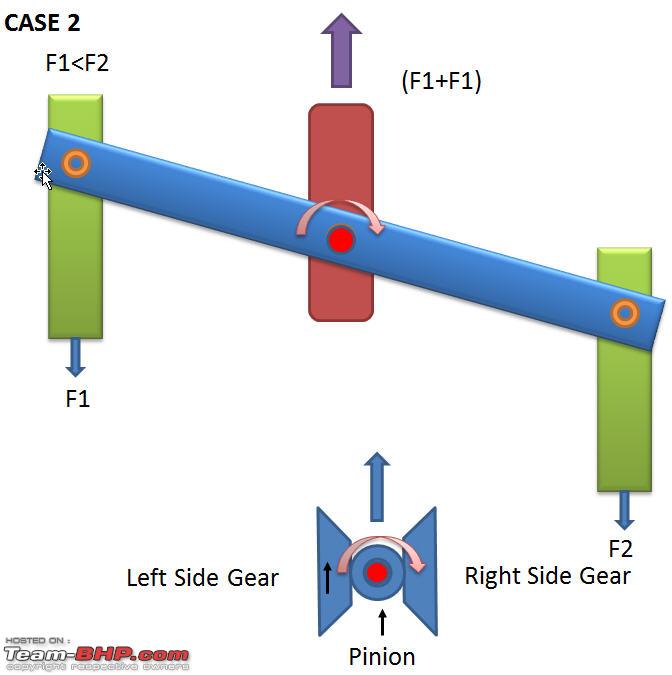
Case II- The vehicle takes a right turn or the resistance on the right half shaft is higher.
Torque generation and distribution-case2.jpg

In case 2 F1<F2 which causes this imbalance. The Blue link applies forces F1a and F2a on green links respectively.
F1a=F1
Here F1a (applied) = F2a. (Being the property of the link to distribute forces equally)

But F2(external force or resistance)>F2a which causes the right green link to stay where it is and the left green link moves ahead. This causes the turning effect in the pinion. The effect is clockwise.
This clockwise movement of the pinion gear forces the left side gear to rotate further relative to the right side gear.
Note,
Here F1= F1a and F2a=F1a also F2a<F2

All the above forces you can convert them into torques by multiplying them with the respective radius of application of forces.

So if left wheel is in air, F1= minimum.

The centre link when rotating about the red pin will exert equal forces on both the sides as its the same single link throughout.
So F1a= F1

and F2a=F1a and

F2a being less than F2 will not be able to rotate the F2 wheel and the left wheel will go on spinning.

Note- If a block requires a force of 20 N to move and we apply 10N. The block will not move but that doesnot mean that we have not applied 10N force to it.

Similarly If in the above case we apply F2a(=F1a) to the right side green link. The link wont move because it is being pulled by F2 which is greater than F2a. Or that means the right wheel on hard rock will remain stationary where as the left wheel in the air will start spinning.

The more you press accelerator, the more the engine rpms will be and so the left wheel rpms will rise further.

@ Sutripta Sir I agree.

Now I am exhausted explaining the differential and its torque distribution phew!

Off topic-

I remember one stupid thing I did in my Final Engineering exams. Differential was my favourite topic because it was difficult to understand in my time when I didnt had access to internet or any physical models.I didnot had any oppurtunity to even see a real opened differential, I just had to imagine to understand it. A very harsh period for my brain indeed! The limited books available for reading used to explain the differential working mathematically. Now tell me how one can see equations at play in the actual gears rotating there? Many of the authors which I read explained differential in this dumb mathematical way of adding rpms N1+N2 and N1-N2. No book which I had read had mentioned that the planet pinion gear is free to rotate on its own axis. I used to think that the planet pinion gear is splined to its pivot pin which in turn is fixed to the differential casing without any rotation on its own axis, causing a lot of trouble for me.

In my last year of Engineering I had a elective subject of Automobile and in the Final exam I got a 8 marks question on differential.
I was so obsessed with differentials that time that I wrote 8 pages of explanation of differential its working explained in a non mathematical way and by different analogies. I spent nearly two hours writing this and I forgot that my total exam paper was of 100 marks!
Obviously I was not able to answer all the questions in time (inspite of me knowing the answers) and had to finally settle with not so good marks :(

Last edited by amit_purohit20 : 6th January 2014 at 01:58. Reason: Additional points added.
amit_purohit20 is offline   (4) Thanks
Reply

Most Viewed
Thread Tools Search this Thread
Search this Thread:

Advanced Search

Copyright ©2000 - 2024, Team-BHP.com
Proudly powered by E2E Networks