| |||||||

| Search Forums |
| Advanced Search |
| Go to Page... |
| View Poll Results: Poll canceled. | |||
| option 1 | | 0 | 0% |
| option 2 | | 0 | 0% |
| Multiple Choice Poll. Voters: 14. You may not vote on this poll | |||
 |
| Search this Thread |  97,583 views |
 24th February 2023, 23:30
| #301 | |
| BHPian Join Date: Apr 2017 Location: NCR
Posts: 319
Thanked: 1,606 Times
| Re: Torque generation and distribution Quote:
Consider torque is a rotational effort, which can be approximated by the force applied by your fingers of the rotating hand (right hand) times the radius of the pencil stub. So, you apply enough force on the pencil (such enough to break the fingers if held much tightly). First, you hold the pencil lightly (in left hand) and try to rotate it with another hand. With the aforesaid enough force, it will rotate. Again, you hold the pencil a bit tightly. Even now, if you apply the same amount of force it will rotate, because the force applied was much higher since the beginning to overcome the resistance. Now, consider the fingers of your rotating hands are soaked with oil in such way that they slip on the pencil surface. Again, you apply the same enough force. But the pencil will not rotate. It does not mean that your rotating hand (fingers) is not generating enough torque! Similarly, you run the engine at 5K RPM, for say, or revving even harder as much as you can, and one wheel on the driving axle loses traction; despite the engine producing enough torque the vehicle cannot move on its own. | |

|  (1)
Thanks (1)
Thanks
|

| The following BHPian Thanks Blooming Flower for this useful post: | SS-Traveller |
| |
|
25th February 2023, 00:44
| #302 |
| Team-BHP Support  | Re: Torque generation and distribution Sorry, I am not able to follow your example. What is 'enough' force? It is the same amount in each case, or different in each case? Let's assume it is same, say 20Nm, which is enough to break fingers as you say. Case 1: Pencil lightly held To apply 20Nm to a lightly held pencil, it has to be rotated at a very high rpm. (can fingers really do this?) Case 2: Pencil tightly held When you apply 20Nm to a tightly held pencil, it will now rotate at lower rpm than before. Tighter the grip (load), lower the rpm. Case 3: Rotating finger socked in oil You won't be able to apply 20Nm to the pencil if it is slippery. Can a rockclimber climb a 30ft high smooth wall with his barehands? He simply won't be able to apply force to lift himself. No grip, no climbing. Similarly slippery turning finger won't apply any force to the pencil, so you won't be generating any torque. Last edited by Samurai : 25th February 2023 at 23:19. Reason: typo |
|
| ()
Thanks
|
|
25th February 2023, 01:13
| #303 | |
| Distinguished - BHPian  | Re: Mahindra Thar : Official Review Quote:
As soon as you start moving stuff on earth horizontally you also need to figure in things like aerodynamics, wind resistance etc. Jeroen | |
|
| ()
Thanks
|
|
25th February 2023, 01:34
| #304 | |
| Distinguished - BHPian | Re: Torque generation and distribution Quote:
Neither the Force due to combustion is constant nor is the arm that creates torque constant. The crank turns around at 0o and 180o the arm is actually exact zero! So is the torque. At 90o past top dead centre the arm is maximum. On the expansion stroke this does not necessarily coincide with the most force exerted on the position due to the combustion/expansion. So the amount of torque depends/varies depending on the crank position, how the combustion and expansion takes place and in which part of the two or four stroke cycle you are. These varying torque values can create problems. Can cause vibration and undue stresses. A flywheel is partly there to dampen out that effect. (Among other things). On larger engines you might also find dynamic balancers. ((E.g. my Jeep Cherokee) On both petrol or diesel engines as a rule of thumb to calculate the force on the piston you need to look at the pressure in relation to the position of the piston. If you know the dimension of the piston and the pressure you can calculate the theoretical force. For practical purposes you need to also consider centripetal forces (depends on rpm, mass and stroke). Also, you need to add in the gravitational constant and the forces that it creates. So it is a bit more complicated. But on both petrol and diesel engine you will find that the pressure in the cylinder rises during compression and peak during ignition, which usually start a bit before top dead centre and ends just after top dead centre. The pressure peaks and as the pistons moves downwards the pressure drops as well. So nothing constant when it comes to forces or arms and thus torque. Remember torque is a static unit! Nothing moves, its engineering unit is Nm. You need to calculate torque for every position of the crankshaft and it will be different for all those different positions. If it is a two stroke you will need to calculate it for 360o of crank rotation. For a four stroke you need to calculate it for 720o degrees of crank rotation. Usually this gets plotted out as a function of piston stroke. Add RPMs and you have your power. It is an important part of an engine design. This will also for instance allow you to dimension the bearings and bearing support correctly. Another fact: on many engines if you run the engine at high RPM with no load the crank might actually push into the top of the bearings, rather than the bottom. The centripetal forces are larger than the forces generated on the piston from combustion! Werkspoor TM410 marine diesels had this problem initially. Nobody had thought of this initially and only designed the bearings for running under high RPM and high load. Jeroen Last edited by Samurai : 25th February 2023 at 07:34. Reason: typo fixed | |
|
| (2)
Thanks
|
| The following 2 BHPians Thank Jeroen for this useful post: | Samurai, SS-Traveller |
|
25th February 2023, 07:05
| #305 | |
| Distinguished - BHPian Join Date: Oct 2009 Location: Chennai
Posts: 4,438
Thanked: 11,488 Times
| Re: Torque generation and distribution Quote:
| |
|
| (1)
Thanks
|
| The following BHPian Thanks dhanushs for this useful post: | Blooming Flower |
|
25th February 2023, 07:59
| #306 | |
| Team-BHP Support | Re: Torque generation and distribution Quote:
Also, another point. We are not trying to discover the science or physical laws behind the working of a gearbox. Those were discovered centuries ago. This is settled science, and nothing like string theory. | |
|
| (2)
Thanks
|
| The following 2 BHPians Thank Samurai for this useful post: | Jeroen, tsk1979 |
|
25th February 2023, 09:44
| #307 | |
| BHPian Join Date: Apr 2017 Location: NCR
Posts: 319
Thanked: 1,606 Times
| Re: Torque generation and distribution Quote:
However, in all my previous posts, I used the term 'usable' and 'available' torque. I understand how load or external resistance play role in engine torque and power generation. When an engine is running idle in neutral at high RPM, it generates energy, and this will proportionally vary with the RPM (not linearly, of course, as several other factors come into pictures.); and during this high RPM idle run, I completely agree the load vs torque curve will be different. The easiest example I recall-- in a small pandal of our vicinity, when the electrical load is increased how the so called, popular single cylinder diesel engine behaviour changes, and it's clearly can be sensed through the change in how it sounds! For this matter, if we run a vehicle engine at full throttle for several hours it obviously produces enough energy which is not 'usable'. Here, 'usable' means if the energy could be used to move the car from point A to point B. But that does not mean that with the increasing RPM, in absence of the 'load', there is no increase in torque also. This phenomenon does not essentially change the inherent working principle of a differential. If you put a PTO device (say a sugarcane juicer) between the gearbox/transfer case, and the differential connected by a propeller shaft in continuity, the engine will produce the 'engine load torque' from the load of the PTO device. At this condition also, if a wheel in the driving axle loses traction, all the 'available' torque through the propeller shaft will be transferred to it only. OTOH, are all the owners of current generation Thar fed with wrong info. in the official owner's manual regarding how BLD works? Is it going to get revised in coming days? Last edited by Blooming Flower : 25th February 2023 at 09:47. | |
|
| (1)
Thanks
|
| The following BHPian Thanks Blooming Flower for this useful post: | GrammarNazi |
|
25th February 2023, 10:47
| #308 | |
| Distinguished - BHPian | Re: Torque generation and distribution Quote:
| |
|
| (2)
Thanks
|
| The following 2 BHPians Thank SS-Traveller for this useful post: | Blooming Flower, Jeroen |
|
25th February 2023, 11:33
| #309 | |
| BHPian Join Date: Apr 2017 Location: NCR
Posts: 319
Thanked: 1,606 Times
| Re: Torque generation and distribution Quote:
Anyways, imagine the propeller shaft of a vehicle is somehow connected with a massive ship diesel engine. No doubt, at the idle condition, with the lowest ever RPM (to run the engine), the 'available' torque value of the ship engine is much much higher than the peak 'engine load torque' of the original vehicle engine. Do you still believe the vehicle can move with one wheel on the drive axle without traction? Or, the ship engine too cannot generate much torque to move out the vehicle without 'engine-load' or resistance? Is the working principle of the differential altered? | |
|
| ()
Thanks
|
|
25th February 2023, 11:40
| #310 | |
| Distinguished - BHPian | Re: Torque generation and distribution Quote:
I have come across all sorts of torque sensors used for R&D design on car axles and such. E.g. https://binsfeld.com/torquetrak/markets/automotive/ On ships propellor shafts torque is measured by means of torque sensors. They are incredibly sensitive. I know we had several set ups in our lab at college. We had a 25 cm thick metal round bar with very simple strain gauge attached to it. With a simple pliers we would grap it and apply some force. It was surprising how little force was needed to get a response from the strain gauge! That was over fourth years ago. Sensor technology has come a long way. Jeroen | |
|
| (2)
Thanks
|
| The following 2 BHPians Thank Jeroen for this useful post: | Blooming Flower, SS-Traveller |
|
25th February 2023, 12:21
| #311 | ||||
| Distinguished - BHPian | Re: Torque generation and distribution Quote:
Here the universal joint of my Jeep taken apart on my work bench. You tell me how it evens out fluctuation of torque?? There is no mass or anything else that would even out fluctuation of torque. 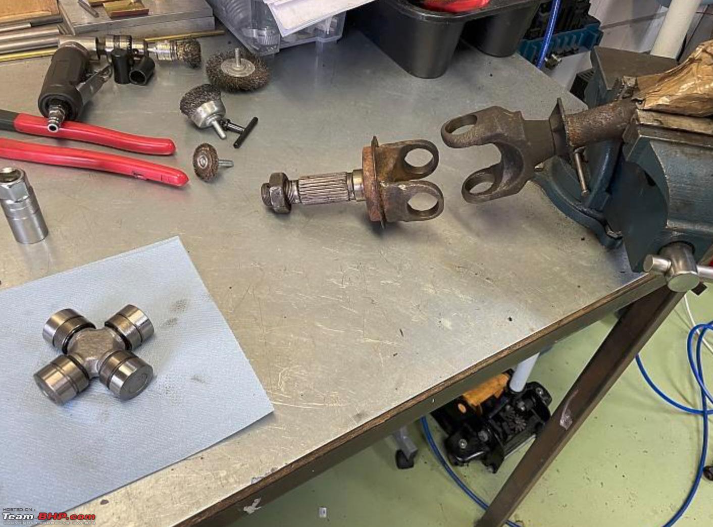 Contrary to popular belief, universal joints are not sort of rubbery floppy things. They are purely mechanical and all metal/steel. It is used to connecting rigid shafts whose axes are inclined to each other. They need to be as rigid as possible, in order to work efficiently. So they will “transmit” if you like torque and all fluctuation of torque from one shaft into the next. As I mentioned earlier not only the flywheel, but on some cars they use what is known as dynamic or harmonic balancers. Here you see an image of the harmonic lancer of my Jeep. It sits on the front of the engine on the crank shaft, hence the seal you see there as well. It is also the pulley that drives the various engine accessories (alternator, AC compressor etc). 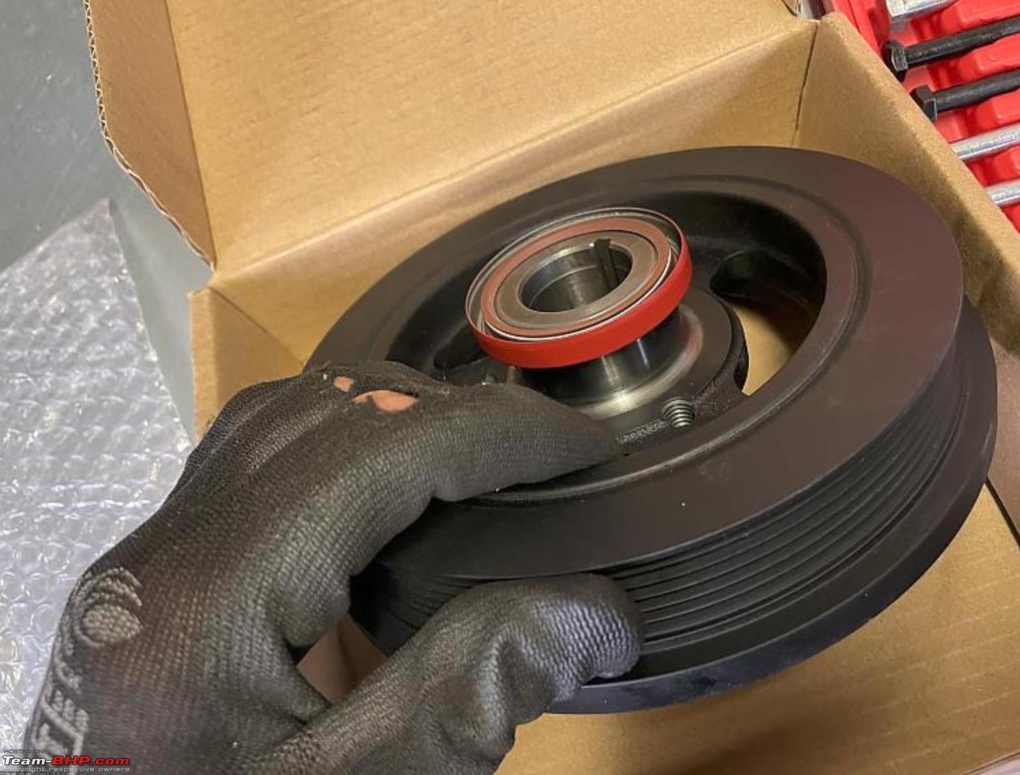 These harmonic balancers or dampeners are made of two steel parts held together by rubber. So they can move or rather rotate respectively from each other, which is what evens out fluctuation of torque. These harmonic balancers are often used on cars that have relatively small (weight wise) fly wheels such as the Jeep. Also of course, you have the dual flywheel, which is simply put, a combination of a regular flywheel and a harmonic balancer, from a principle point of view. Quote:
Quote:
Quote:
Although simplifying can be a powerful tool in explaining yourself, it takes a real expert to do so. If you don’t understand the physics behind torque, no amount of "dumming" it down is going to make a credible simplified story. Appreciate all your efforts though. Of course, I might be wrong on all of this as well. It has happened before! I am just an old git these days. Jeroen Last edited by Jeroen : 25th February 2023 at 12:32. | ||||
|
| (4)
Thanks
|
| The following 4 BHPians Thank Jeroen for this useful post: | Axe77, Blooming Flower, Prowler, Samurai |
| |
|
25th February 2023, 12:33
| #312 | |
| Team-BHP Support | Re: Torque generation and distribution Quote:
 | |
|
| ()
Thanks
|
|
25th February 2023, 13:50
| #313 | |||||
| BHPian Join Date: Apr 2017 Location: NCR
Posts: 319
Thanked: 1,606 Times
| Re: Torque generation and distribution Quote:
Quote:
Quote:
Quote:
Quote:
Last edited by Blooming Flower : 25th February 2023 at 13:57. | |||||
|
| (2)
Thanks
|
| The following 2 BHPians Thank Blooming Flower for this useful post: | Jeroen, SS-Traveller |
|
25th February 2023, 22:17
| #314 |
| BANNED Join Date: Mar 2011 Location: hump city
Posts: 1,293
Thanked: 5,892 Times
| Re: Torque generation and distribution I am an electrical engineer, so don't understand 90% of the jargons used here, so unable to form a coherent understanding of who is making what point exactly. But inorder to check whether I am getting a sense of the direction this discussion is going, I would like to compare two systems - an electrical motor and an IC engine. Both generate torque and both have rpm ; and both obey the fundamental tenet of energy calculation : energy/sec = power = torque x rpm So far so good, all of us agree. Electrical equivalent of fuel is the current, Electrical equivalent of accelerator pedal (or throttle) is the voltage. Electrical equivalent of flywheel is a parallel capacitor (simply there to 'smoothen' out 'pulses' of torque generation) Say the load on the electric motor is gradually increasing (it's lifting a sand bucket through a chain mechanism and sand is constantly pouring into it from a hole) - even without voltage change, it will 'automatically draw more current' and produce more torque, to combat the increasing load. And as it does so, the rpm will keep coming down gradually, until a point where it can no longer draw anymore current, and stall (and possibly burn or melt the windings from the highest current at the time of stalling). So what happened here ? The system is inherently having automatic feedback (higher load making it draw higher current) until a certain 'load limit' is hit. For the next stage, there is no other option other than increasing the voltage, further enabling higher current for higher loads. This is similar to the case of a constant throttle (for simplicity sake, consider a petrol engine with a pure mechanical butterfly valve as throttle) for the vehicle to climb up a slope, the ECU decides by itself (automatic feedback) to burn more and more fuel, continuously suffering vehicle slow down, until it can't do it anymore, and stalls the vehicle. For the next stage, there is no other option other than increasing the throttle (voltage) to enable more air and further enabling more fuel for higher loads. So in both cases, the load-demand 'automatically' translated to torque-demand and made the system generate more torque. By drawing more current in one case and by drawing more fuel in the other case. However, this happened only until a load-limit window was breached. The provision of various gears and exercising the available choices amongst them ; in the path between generation point and load point , is simply 'widening the window' of 'automatic response by the system'. So we can all agree that 'load' influences how much 'torque' is generated. However, it happens only within a 'window of operating points' - beyond that, to generate more torque, some 'external action' like more throttle to enable more air or more voltage to enable more magnetic field is needed, so that even more fuel or even more current can be drawn and utilized to generate more torque. So what happens when an engine in neutral / motor at no load , is given more throttle/voltage ? The load is purely the 'rotational inertia' present on the disconnected shaft. Since this "load" is unvarying, as soon as the system generates the torque to overcome this, all the rest of the energy provided simply translates to more and more rpm. More throttle/more voltage - simply more rpm, no change in torque generated. Hence, my take on the matter is, within a window of operation, the load indeed does decide what should be the ratio of split between torque and rpm, for the energy that is made available to the system. If the load increases such that a point is hit where (100% torque, 0% rpm) occurs, then more energy needs to be made available for this new load to further decide what should be the split ratio between new torque and new rpm. |
|
| (3)
Thanks
|
| The following 3 BHPians Thank venkyhere for this useful post: | Blooming Flower, keroo1099, Samurai |
|
26th February 2023, 10:58
| #315 |
| BANNED Join Date: Mar 2011 Location: hump city
Posts: 1,293
Thanked: 5,892 Times
| Re: Torque generation and distribution I understand that this thread originated due to the debate about MLD, BLD, LSD etc getting too technical in another thread. The thread is filled with jargons and technical terms to the level that a layman will find it hard to understand, so let me try to translate a bit : What is a differential and why was it invented ? When the non-steered rear wheels of an RWD vehicle are subjected to a turn, say a right turn, there has to be a mechanism to allow the inner wheel to turn at a lesser rpm than the outer wheel, so that when the vehicle changes it's orientation gradually from straight to 'right turned' , no tyre rubber 'screeches' against the road or 'slips' against the road and gets shaved off. Turns out, the mechanism is 'already there', because the rubber that forms the tyre, needs to 'twist' at the contact patch, when wheels which have no steering have to 'turn'. Utilizing this fact, a basic 'differential' (called open differential) was invented, with a system of rotating cogs that works in the following way : A way where the 'energy' gets split equally amongst both wheels - the inner rear wheel experiences more tyre rubber twisting load on it's contact patch than the outer wheel, because it's trying to achieve a sharper change in orientation due to smaller turning radius => more torque demand presented by inner wheel w.r.t outer wheel => the ratio of rpms between wheels is inversely proportional to the ratio of torque loads between the wheels. Effectively torque x rpm (the energy/sec) on each wheel is the same, and this is a neat mechanism. However, all hell breaks loose (the energy getting split equally goes out the window), when there is very poor or no friction on offer, on one of the wheels amongst this left and right. The design of the open differential is such that the 'engine torque' that needs to be generated is defined (through gear ratio translations of course) purely by the smaller of the two torques demanded by the left and right wheels. This aspect creates an issue. When one wheel is on a slippery surface (sand or ice) the 'load torque' on that wheel is effectively the rotational inertial mass of the wheel+tyre+brakedisc of that wheel alone. That means even if the 'other' wheel is sitting on a proper grippy surface, the torque-demand or torque-load presented to the engine is that of the slipping wheel, which is low. The engine will only generate as much torque as is presented as load to it (previous post above). So now, there is one wheel with grip, and the open differential is ineffective in 'utilizing' it. In other words, the open differential is something that allows the flow of energy through the path of least resistance. To combat this problem, the question now is, 'how to present a higher torque demand to the engine, when one of the wheel is simply slipping and presenting none'. Thus was invented things like MLD, BLD, LSD etc. (all jargons, but with careful meaning hidden in them - mechanically locking, brake locking, limited slip). All of these are trying to build a relationship between the left and right wheels, something that the open differential never allows. These jargons are trying to 'counter' the fundamental edict behind the invention of the open differential - FROM "let the load dictate how much torque demand needs to be presented to the engine" TO "let us artifically remove the independence of the left and right loads from each other and then present a 'cooked up' torque demand to the engine". In case of MLD, the left and right are simply locked into a single solid axle, the left and right have to rotate at the same speed. In case of LSD, there are clutch packs present, that can control the 'resistance to turning' offered by left side or right side. In case of BLD, the brake computer (or ABS computer) externally uses it's brain, to actually press the brake discs to 'artificially' create extra torque load wherever necessary. In case of open diff, the effective torque demand to engine is the smaller of the two "contact patch friction load" required to rotate the individual wheels. In case of locked diff (MLD), the effective torque demand to engine is the larger of the two "contact patch friction load" required to rotate the individual wheels. In case of a slipping diff (LSD/BLD), the effective torque demand is the smaller of (contact patch friction load + brakes pressed load) required to rotate the individual wheels. Hope this is useful to a layman reader. Last edited by venkyhere : 26th February 2023 at 11:18. Reason: more clarity |
|
| (5)
Thanks
|
| The following 5 BHPians Thank venkyhere for this useful post: | Blooming Flower, Car Stalker, Jeroen, keroo1099, SS-Traveller |
|