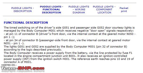
Part II - Front Doors and ORVMs
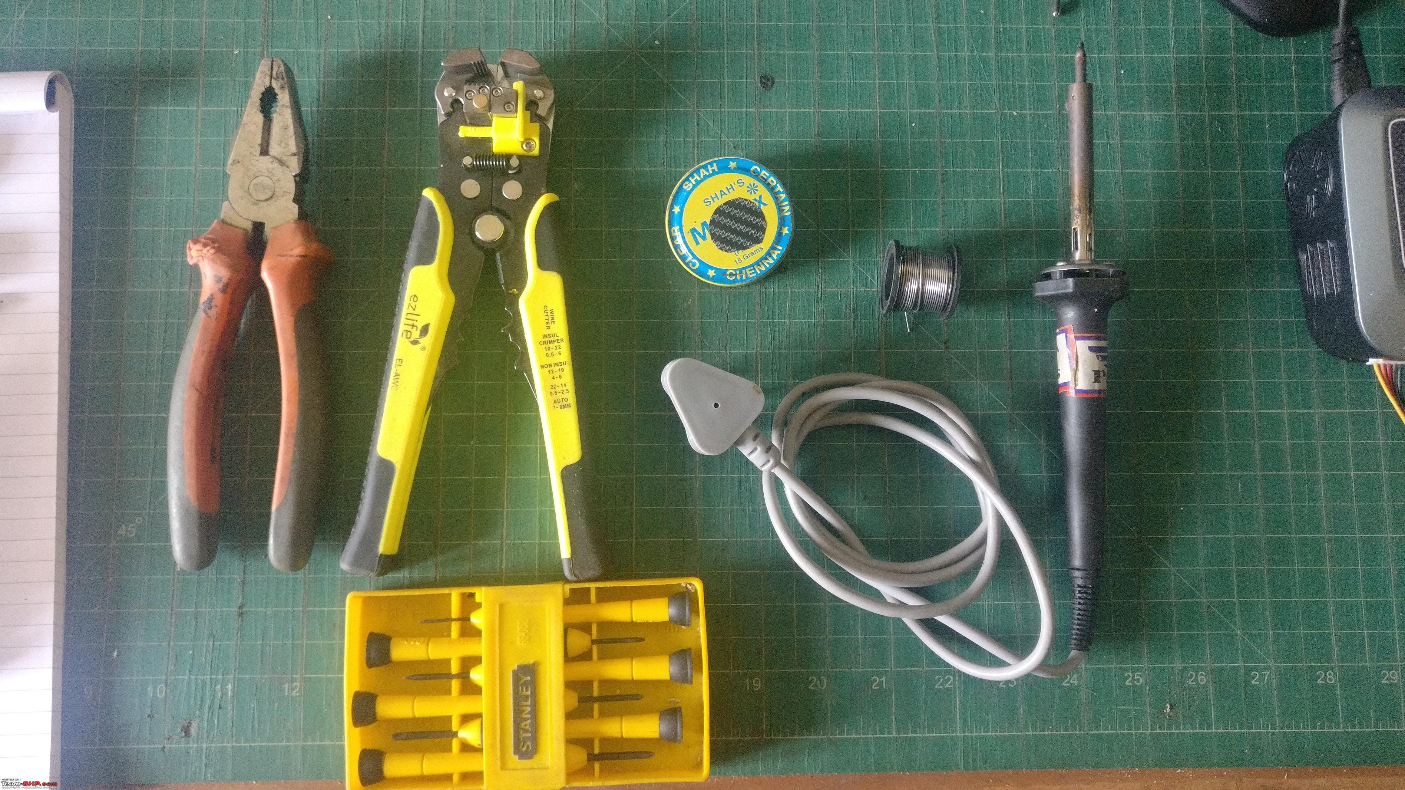
Tools used for this part of the install -
Crimping tool, Wire stripper, Screw Driver, Dremel & Vice grip
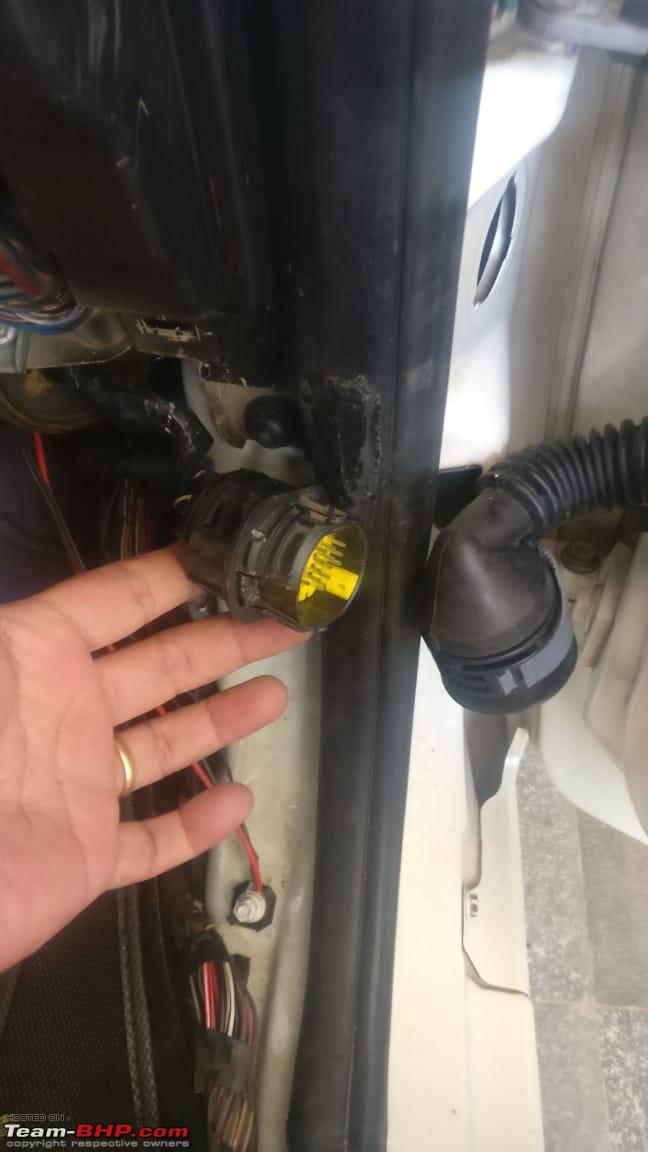
Step 1 - Routing the wires through the door jamb connector
I measured and cut wires which will be sufficient from the location of the distribution box I step up and placed inside the center console, to the door. Then I crimped on one of the male pins to one end of the wire and connected the other end to the screw terminal block in the distribution box. Taking out the door jamb connector is a bit tricky.
Pulling that grey ring separates the two parts of the connector. The male pins are housed in the part that is fixed to the door frame. This part has three locator tabs and 2 locking tabs. The two locking tabs have to be pressed simultaneously and the connector pushed in. Those locking tabs were pretty hard to press, but I was finally able to use a vice grip setup with just enough pressure to press the tabs and not break the connector. Once I had it loose, I pulled into the car.
Now I identified a spare connection blocked off with a green plastic pin. I then pulled out the green pin and inserted the male pin, making sure that it was inserted all the way inside and locked in place. Then I re-positioned the connector through the frame and inserted it back into the hole. The three locator tabs come in handy to ensure that it is fixed the right way up.
Next, I took another length of wire, crimped a female pin onto one end. Then I removed the rubber boot on the part fixed to the door & inserted it into a spare connection, making sure it is in the same position as the part on the frame. Now I pushed the rest of the wire through the rubber boot and into the door. Now I fixed the rubber boot back and connected the door jamb connector back. In the disconnected position, it is easy to accidentally close the door and crush the connector.
Now on to opening the door pad. First, I lifted the control switch board on the arm rest. There is a small gap on one end. Inserting a small screw driver into the slot and lifting it up releases the panel, Then the connectors underneath have to be disconnected. The number of connectors will depend on the controls. On the driver side there were more connectors, but on the passenger side there was only one.
Moving on to removing the door pad, there are three allen head screws - one behind a small tab behind the inside handle and two more under the armrest handle
After taking these out, the next step is to take out four Philip head screws along the bottom edge of the door pad.
Once these screws are taken out, the door pad, which is now held by plastic push pins along the vertical edges, comes out with some gentle pulling from the bottom. Once all the plastic pins are released, the door pad has to be lifted up, as it is hooked up along the top edge along the window glass.
After getting the door pad free, the connection to the tweeter has to be undone. Also, the door lock release handle connection has to be disconnected. To do this, first release the small white tab that lock the cable to the handle. Then release the white cylindrical sleeve from the door pad. Now the cable connection will come out.
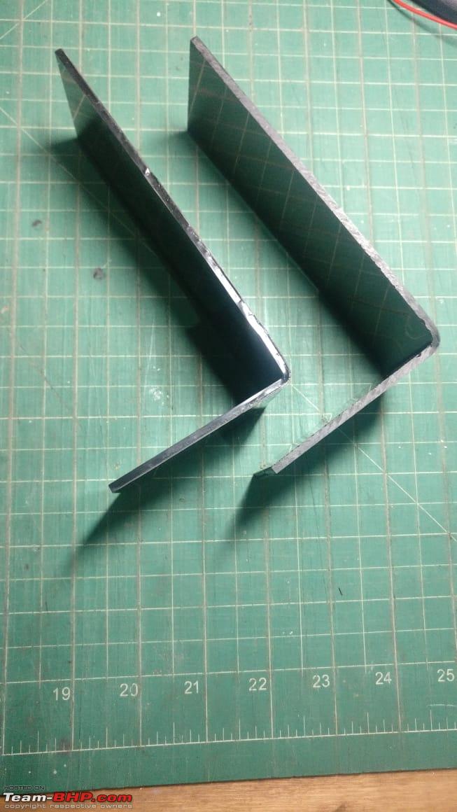
Now the door pad will be free from the door. Next step was to cut the slot for fitting the boot light housing. To do this, I took out the housing in the boot and traced the outline onto a paper. Then I pasted it on a piece of cardboard to make a template. Now I placed the template on the door pad, where I wanted to cut the slot, traced its outline. Then I drilled a series of holes inside the outline and cut the piece away. Finally finished by cutting to the traced line. Now the boot light housing fitted there fine.
The template
Since I did not have the proper female connector for the boot light housing, I decided to crimp on a couple of pins and heat shrink them. I made sure to leave extra length of wire, so that when I source the female connector, I can crimp them on.
Now it was time to move on to the ORVM. For this, I first removed the cover by gripping it and pulling while prying along the top seam with a screw driver (covered the end in masking tape to avoid scratches)
I had already tilted the mirror to the lowest position, so that there was a gap along the top edge. Looking through that the clamping mechanism is visible. Inserting a screw driver into the gap and twisting makes the mirror pop out of the clamps and it comes loose.
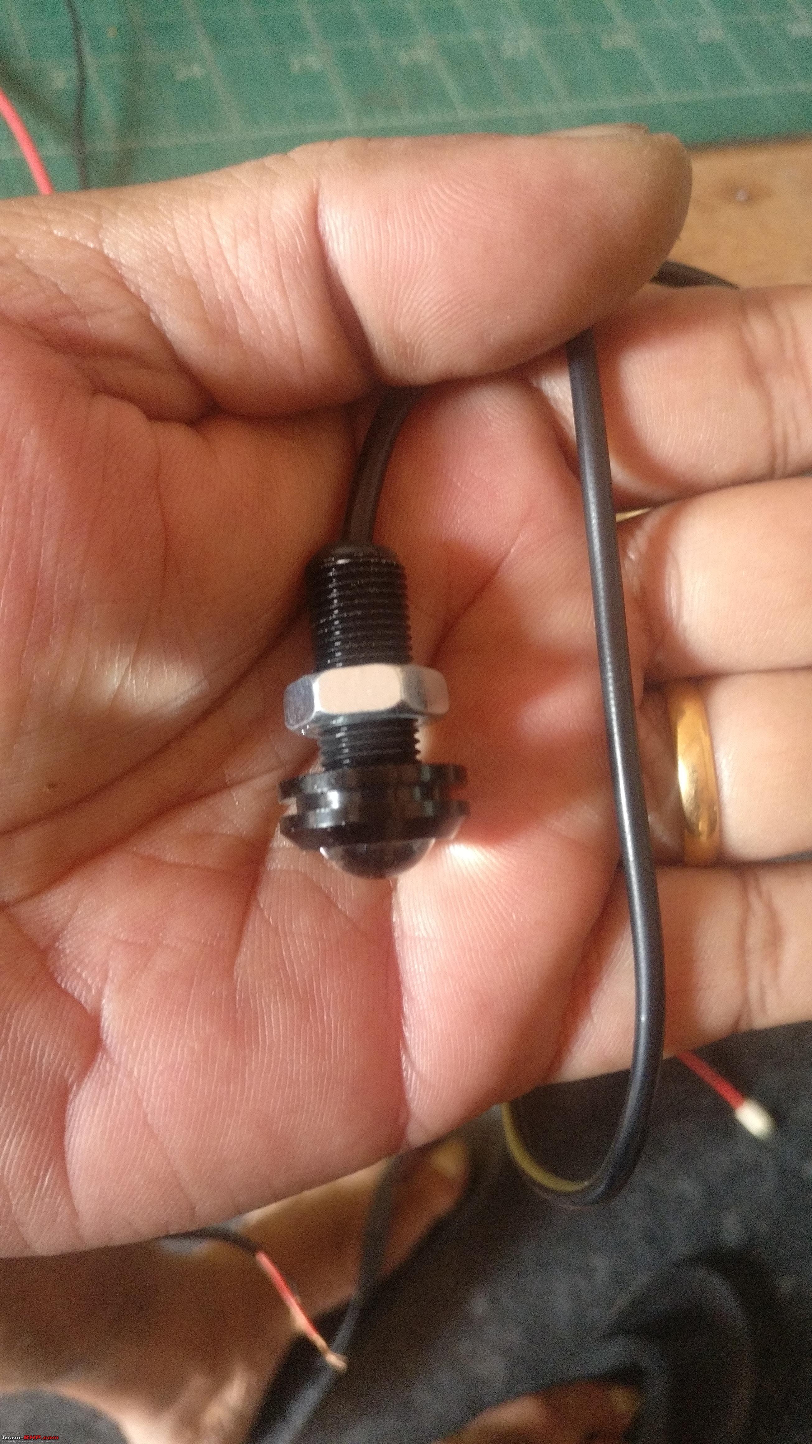
Now I identified the position I wanted the Eagle Eye LED to be mounted and first drilled a small hole in the ORVM casing. Then I enlarged the hole enough for the Eagle Eye to fit through. This can be done with a drill bit, but I chose to use a trimmimg bit in my Dremel
I then mounted the LED and passed the wire through the OE route back into the door panel
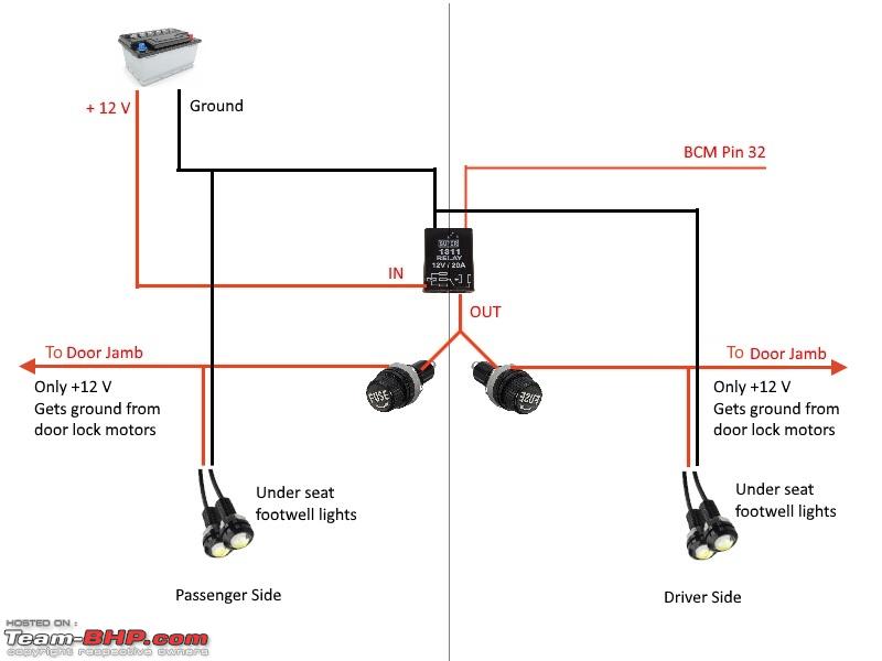
Once I had the wires inside the door panel, I took off the plastic sheet pasted on to the door panel and then connected everything up. Power comes from the wire I earlier dropped in through the door jamb and I drew ground from inside the door from the existing ground wire. I then put everything back, in the reverse order of how I took them apart.
To be continued ...


 22nd October 2018, 15:07

 (19)
Thanks
(19)
Thanks