| |||||||

| Search Forums |
| Advanced Search |
| Go to Page... |
 |
| Search this Thread |  21,238 views |
 18th July 2021, 00:20
| #1 |
| BHPian Join Date: May 2015 Location: Trivandrum
Posts: 82
Thanked: 769 Times
| DIY: Skoda Laura - Custom Instrument Cluster MFD Display Hello BHPians! I hope you all are doing well. Owning an older generation German car is a delightful experience in a lot of ways only a petrol head can understand. However, there is a very dark side of that ownership experience which is pretty much a nightmare - Unavailability of parts most of the times & ridiculous pricing if they're available at the ASC. This is in my opinion why most enthusiastic people change their cars as they age even though they don't want to do it whole heartedly, parts become too hard to obtain even if money isn't a problem, for most people, the time & effort is simply not worth the hassle. Reason why this DIY was attempted is because of such a reason - Super rarity of an instrument cluster LCD & the eye watering cost of replacing it at an ASC. Main reason why this DIY happened is the free time I got due to the COVID19 triple lockdowns here in Kerala. The Problem There is a peculiar issue with the first batch of Skoda Laura CBU cars that came to India, not just on Lauras, this is there in other VAG cars of the same time. The LCD MFD in the instrument cluster on the top variant, L&K goes dim on one side as the car ages. The reason for this is simple, the LCD module is actually two physical LCD modules glued together, both halves have independent electrical connectors, if the LCD driver on one side goes bad that side goes totally off or becomes less bright - This is not an issue with the backlight LEDs, LCD module itself is the issue. VAG quickly identified the problem & from next model year onwards, they revised the design & introduced an LCD panel that isn't prone to this issue. The problem started on my car about 1.5yrs back, just before the COVID19 first wave, I was able to procure a used one from a parts car for swapping it out & learnt that its not possible. It has been bugging me ever since, even though I wasn't able to use the car like I used to thanks to COVID19, it was still bugging me every time I sit in the car, could be my OCD, but it was really bothering me every single time! Remember that the the car is about 15yrs old now! 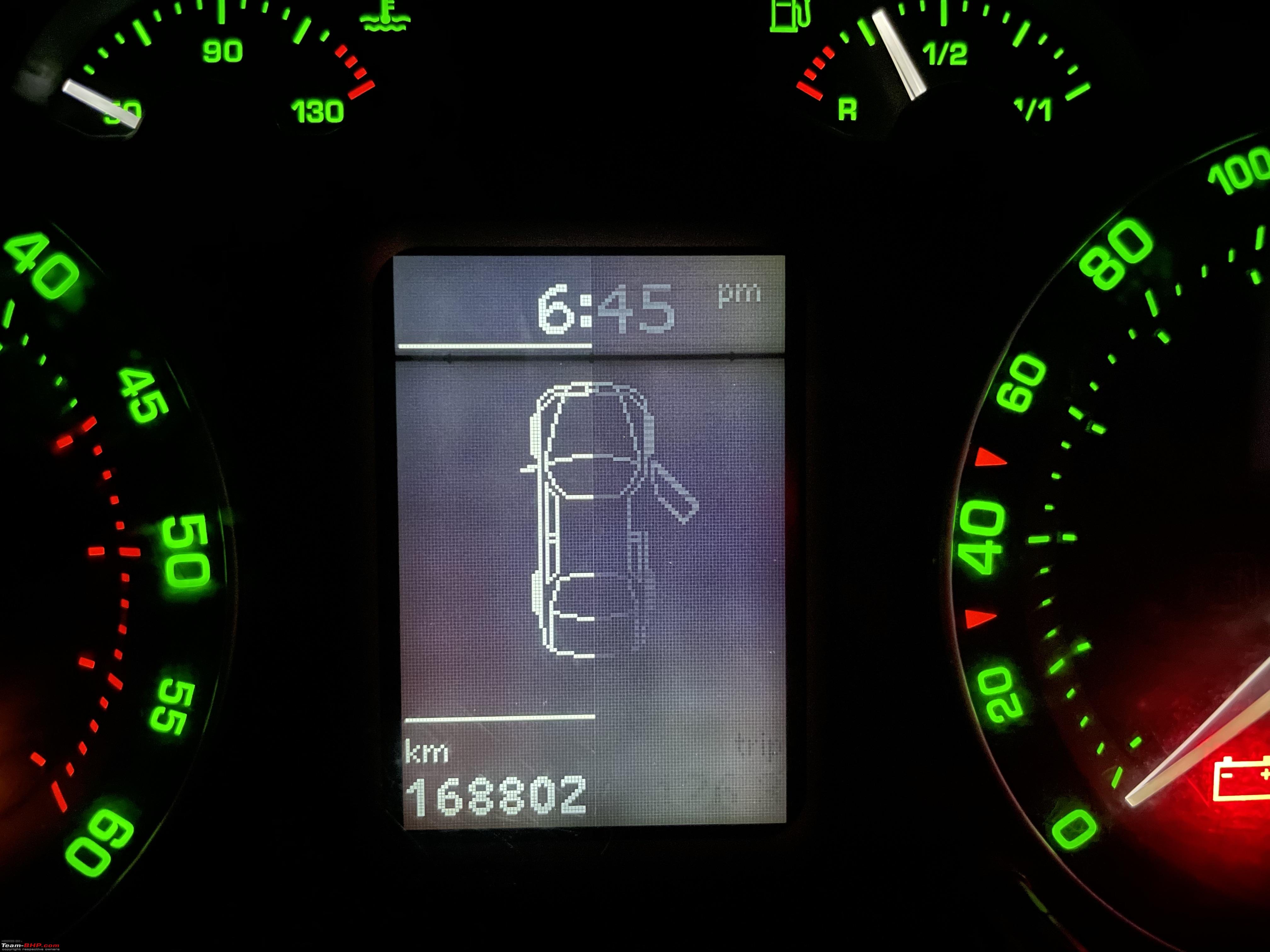 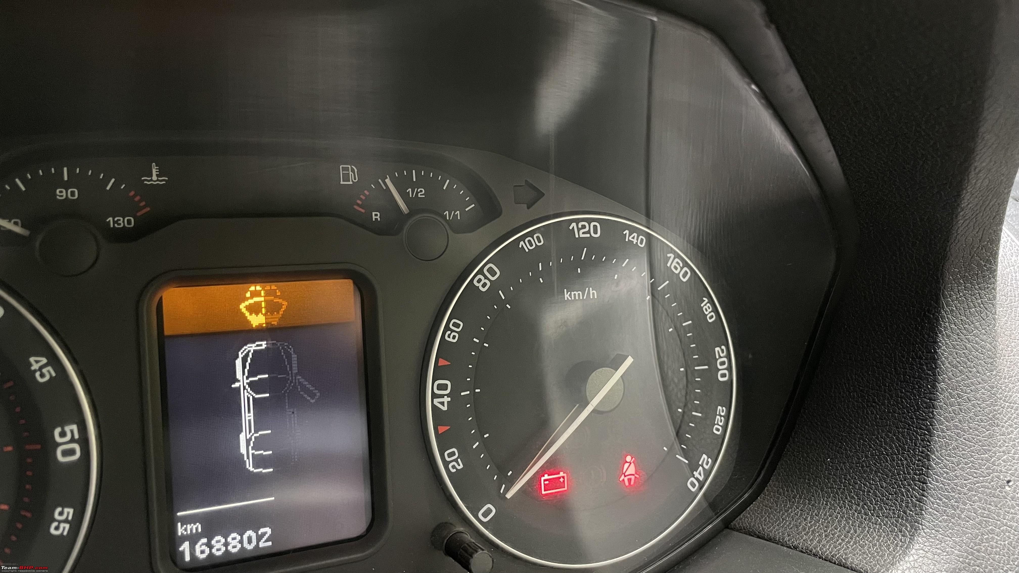 Potential Solutions There are two mainstream solutions to this issue:
My Solution I was trying to get a replacement LCD through my FNG, due to COVID19, that went nowhere. During that time, I came across a video by the Humble Mechanic about an aftermarket MFD display called ColorMFA, video here: This gave me the idea to go by the DIY route. The ColorMFA is a cluster upgrade made by a Russian guy, it costs a lot, but it looks cool & very functional. Unfortunately, its not available or compatible with the Laura(Octavia Mk2). There was an unfinished project that I started a while back, an app for my car - The idea of the app was to control the windows, lights and a few other things through a mobile app via bluetooth. That project never got finished due to the sheer amount of time needed to decode the CAN messages. Now due to the COVID19 lockdown, I had plenty of time in hand and decided to tackle this on my own. Below are the requirements i've set for myself:
For this to workout, I needed to get the following done:
The OEM LCD is slightly smaller in the cluster cavity, which is noticable if you look close enough. I had a 3.5 inch LCD screen which I bought for a different project did fit perfectly, this module can be driven by a parallel interface using a microcontroller. I started out with an STM32 microcontroller, did the CAN Bus implementation on it & all was going well. After a day or two, I killed the module by accidentally supplying 12v - I had no spares for the burnt board & COVID19 lockdowns were in effect. That forced me go with what I had laying around - An Arduino Nano, this is a very restrictive microcontroller but was enough to get the job done. I have quite a few number of these low cost microcontrollers in my parts bin. The LCD I chose initially was really hard to program on, everything had to be doe by hand - If you want to show a text on screen that is right aligned, you've to find the character dimension of the font, multiply that by the number of characters in the text you want to display and subtract it from the width of the screen and use that value as the origin of the text! This was pretty tedious obviously & showing images was super tough, it was really hard to implement the UI on it. Decided to hold the UI development and started concentrating on the CAN Bus decoding part of the project. This was easier this time as I attempted something similar a while back. The Laura has 3 independent CAN Buses:
Decided not to mess around with the drivetrain CAN bus, its a critical system & I didn't wanted to mess with the reliability aspect of the car. Convenience bus was the bus of choice. It can be easily accessed from behind the stereo head unit, I tapped the bus at the connector and extended the bus with a long wire routed via the glove box. Used the free software CanHacker along with an Arduino based hardware interface to intercept the CAN messages flying through the bus. Identifying and decoding messages are a really time cosuming job. You've to look at messages that are changing when you do an action and decode what you want based on what you see as change on screen. Below is a screenshot of the CANHacker application sniffing the CAN Bus.  Obviously this was going to take a lot of time, luckily I'm not the first person sniffing around a VAG CAN Bus! I found a Google Sheet where someone has decoded a lot of CAN Messages of a Golf MKV GTI Convenience Bus: https://docs.google.com/spreadsheets...en&hl=en#gid=0. About 60% of CAN Bus messages were the same on both cars(thanks to VW!), some required modifications to how they're interpreted though. Most of my time was spent on decoding the door open/close status. Some didn't work at all, for example the coolant temperature - it never returned the correct value. By this time, I had a proof of concept running, I was able to get the following details from the CAN Bus:
I wasn't able to decode the time from CAN Bus data correctly, hence I decided to go with a separate module for time keeping. As an additional feature, I've added a digital compass module to my system which will show a compass on the MFD. I used a TIP122 darlington transistor to control the power to modules - This is important because if the modules are kept ON, they'll drain the battery with a few days, especially the LCD needed to be turned off when the car is not in use. For trip data, I'm using the EEPROM thats part of the RTC module. By this time, I came to the conclusion that the LCD module that I'm using isn't going to cut it, it was too much work & the results were not that impressive - too much flickering and screen tearing on changing values. I had a Nextion Enhanced HMI module in my parts bin - This was again part of an unfinished project, I bought this module to build an LiFePO4 powerwall for my house, plan was to use the Nextion module as the interface to the powerwall. It never got finished(never actually started to be honest!) because of reasons, but it did help me here! Developing UI on a Nextion HMI is easy, we can use Photoshop or any other drawing tool to create graphics & use Nextion provided controls such as buttons/text to render whatever we want. It also has a scripting language in place that can be used to write logic within pages. The main advantage of Nextion is that, graphics rendering work is offloaded from the microcontroller, it uses a simple serial interface to change values on screen and for changing pages. Nextion has a GUI application that can be used to design pages through drag & drop. Main advantage here is that, it has a built in simulator. You can validate the functionality before burning the code to hardware, pretty neat! Nextion Editor: 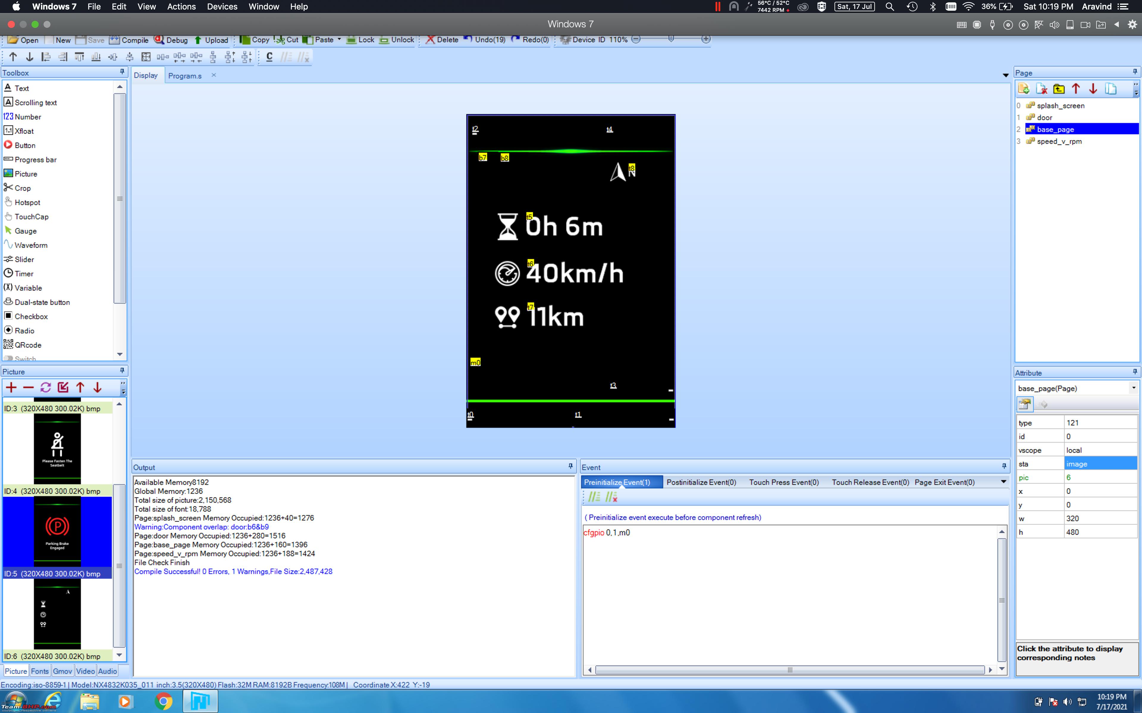 On a high level, this is how the whole system looks like:  The real time clock module & the compass module communicate over I2C bus with the Arduino while the CAN Bus transceiver communicates over SPI bus. Simple Serial communication is used to send data to the LCD module. Below logic flow diagram shows how the power rail & comms is controlled: 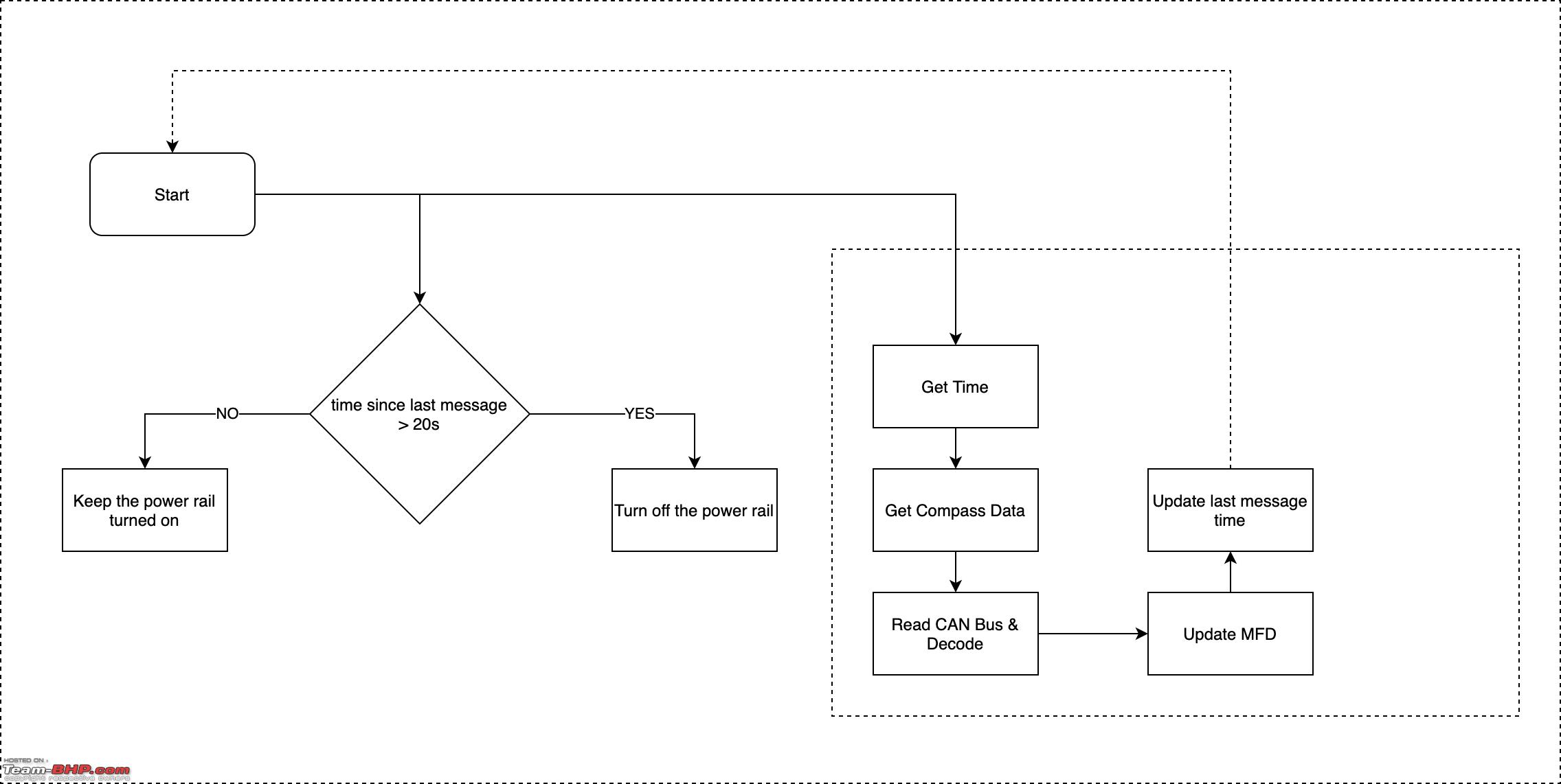 Results Mess of files! 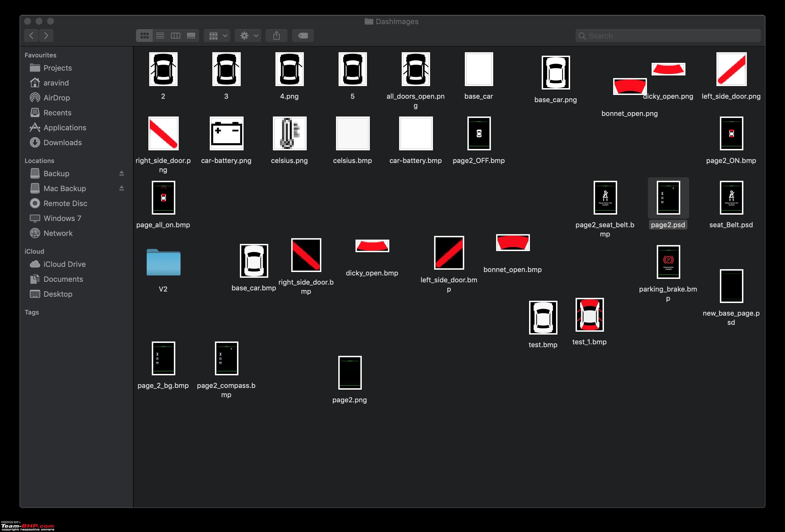 Prototype board: 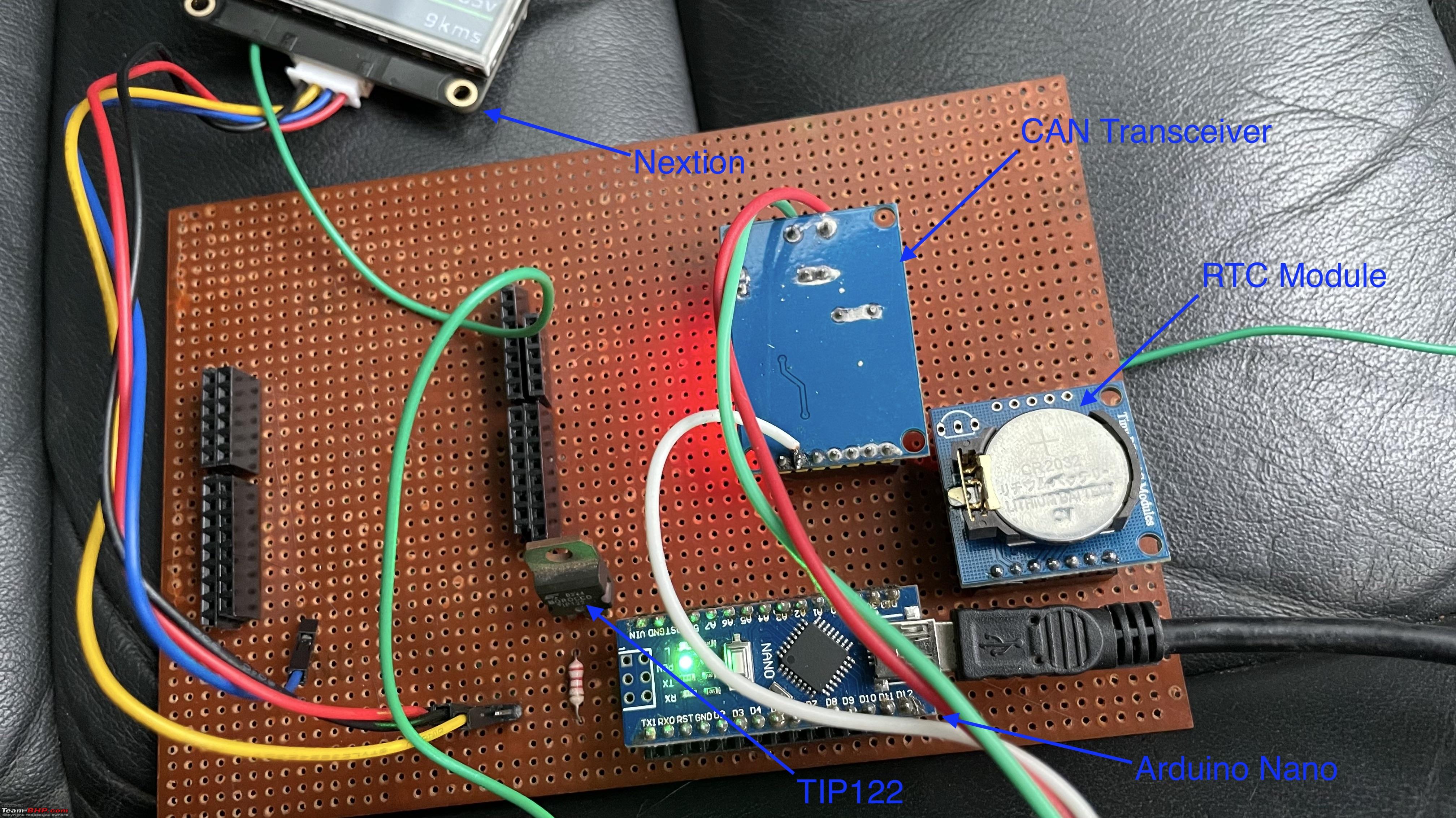 Please excuse the mess! 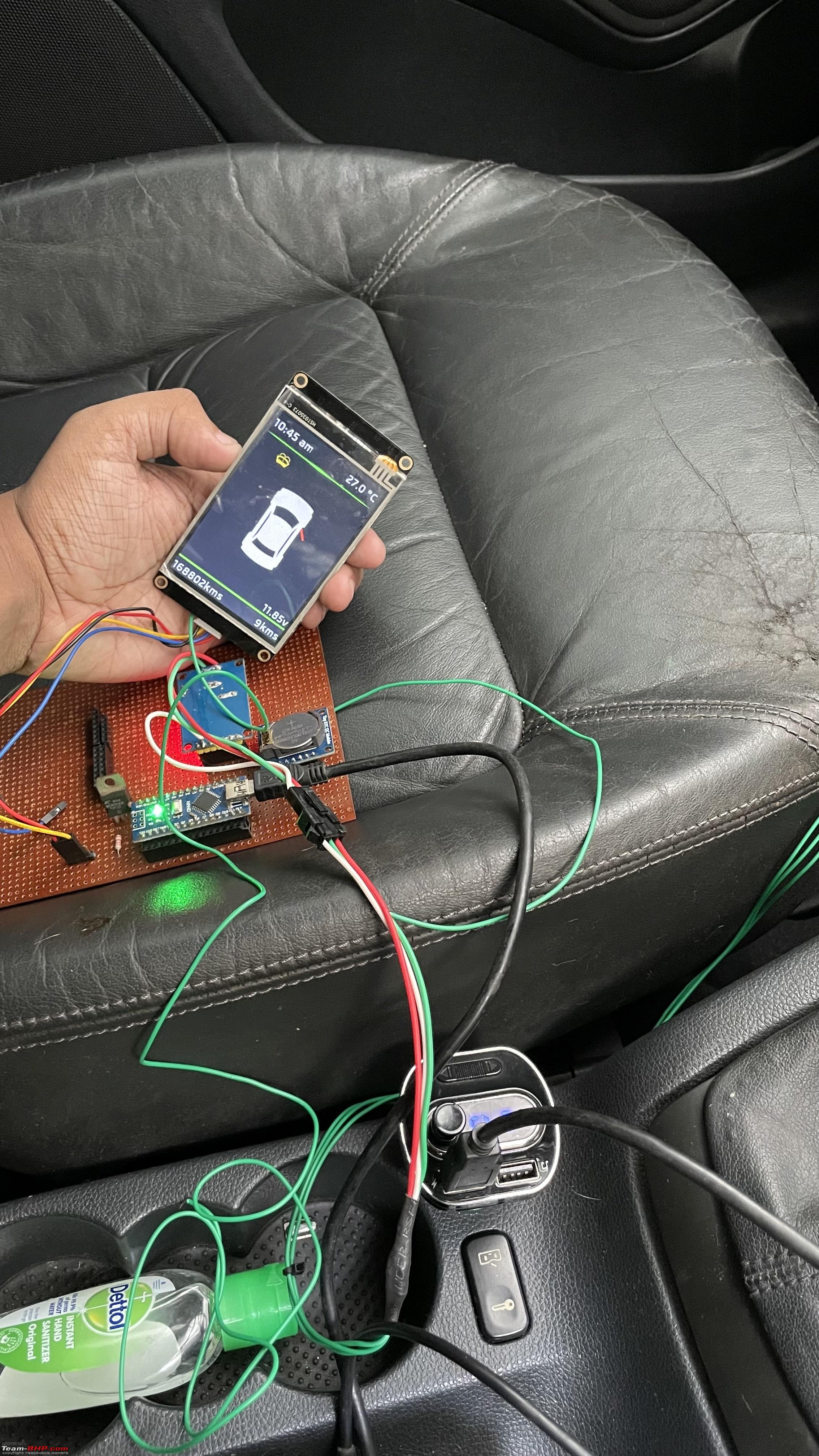  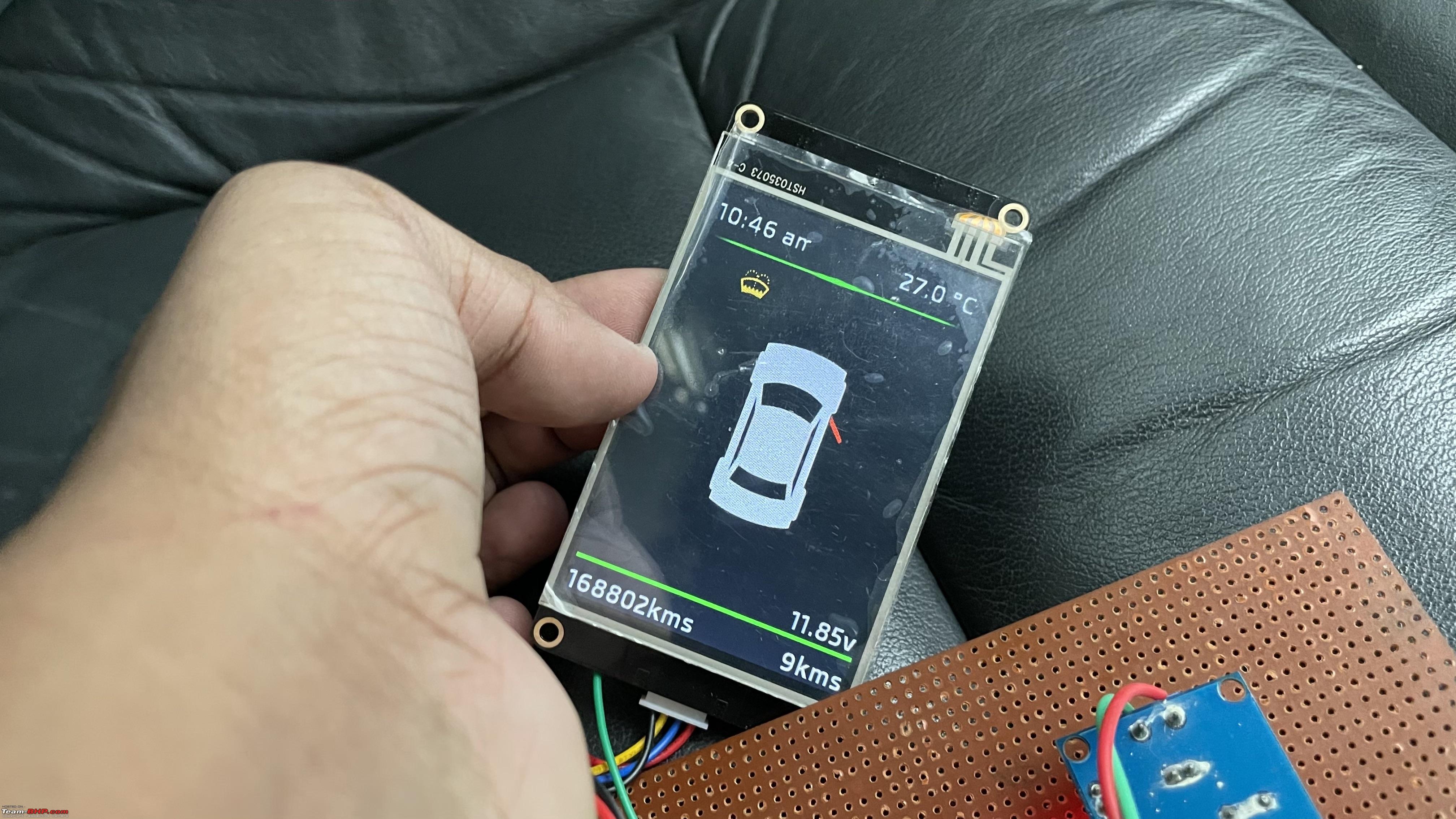 Video In the video, you'll be able to see almost all of the functionalities, including the dimming of LCD backlight. You can also see that the unit turns itself off after about 20 seconds of locking the car. Things That Work Below are the features that work correctly without issues as of now:
Pending Items / Issues As of now, the MFD works fine, however its not without problems. Below are the issues that needs to be sorted:
I'm currently running the setup along side the original MFD in an attempt to identify & fix any issues, will be fixing the screen inside the cluster shortly, will keep the thread updated. As for the sources, I'm planning on releasing the Arduino code, schematics & the Nextion HMI file as an open source project via Github, I'm currently in the process of polishing the edges to make it presentable to a wider audience  As always, thanks for reading! |

|  (82)
Thanks (82)
Thanks
|
| The following 82 BHPians Thank vsaravind007 for this useful post: | --gKrish--, aarnav_b, ACM, aeroamit, agambhandari, Akshay1234, Almoral, anupamsinha, aravindb_0711, Arvi95, ashking101, AShubrah, audioholic, batladanny, Big Smoke, BoneCollector, Carmine_pepper, CEF_Beasts, dailydriver, Desmosedici, dhruvdangi, digitalnirvana, Divya Sharan, DrANTO, eyesice, ferry911, fluidicjoy, Gannu_1, GaryTSI, gasinveins, govigov, GTO, headbanger, Herschey, ike, InControl, jagan88, JatinSharma, jithin23, jothishX, kedar_GT, kutts, lapis_lazuli, lemedico, MaddyCrew, MoTo_meister, Mr.Boss, nagr22, Naveen_0181, Omkar, PearlJam, PM - B, prajwalmr62, pramods, PraNeel, pritanshchandra, Raghu M, redohabitat, Rehaan, Researcher, Sayan, singleton, speedfreak77, sridhar-v, Storm2.0, SuhairZain, svsantosh, Teesh@BHP, Tgo, theexperthand, The_Outsider!, thtechnician, VaibhaoT, vishy76, VivekCherian, vredesbyrd, whitewing, WizSatish, Xaos636, y2s, yajaman99, yesyeswe |
| |
|
18th July 2021, 00:25
| #2 |
| Senior - BHPian | Re: DIY: Skoda Laura - Custom Instrument Cluster MFD Display Fantastic stuff, maybe a bit impractical at the moment. But this is the kind of things that real techies would do for their cars, whatever time it may take. Your new display looks far more modern and up to date than even the current crop of Skodas on sale(read: Kushaq,Rapid) |
|
| (6)
Thanks
|
| The following 6 BHPians Thank agambhandari for this useful post: | AShubrah, digitalnirvana, fluidicjoy, Researcher, VijayAnand1, vsaravind007 |
|
18th July 2021, 00:32
| #3 | |
| BHPian Join Date: May 2015 Location: Trivandrum
Posts: 82
Thanked: 769 Times
| Re: DIY: Skoda Laura - Custom Instrument Cluster MFD Display Quote:
| |
|
| (2)
Thanks
|

| The following 2 BHPians Thank vsaravind007 for this useful post: | aravindb_0711, digitalnirvana |
|
18th July 2021, 00:59
| #4 |
| BHPian Join Date: Mar 2020 Location: KL 01
Posts: 64
Thanked: 343 Times
| Re: DIY: Skoda Laura - Custom Instrument Cluster MFD Display Excellent project @vsaravind007. Good choice to use the Nextion enhanced. I too have one lying around procured from aliexpress for an abandoned project. Had hell of a time making the ui with a tft lcd and arduino gfx libs on a nano for a custom display on my bike few years ago. Doesn't the nextion have an RTC module embedded? Also what's the can transceiver module that you're using? Guess you would have taken care to extend the usb port of the nano to somewhere below the dash to easily reprogram if needed. Nano is no match in speed for the stm32. But since you have used nextion, the load would be pretty much less than those crappy i2c or spi displays. I would go with the rpi zero w, just for fun and all the extra goodies like BT and wifi. Probably overkill and would complicate the coding. I too am from tvm btw. |
|
| (8)
Thanks
|
| The following 8 BHPians Thank jothishX for this useful post: | aravindb_0711, digitalnirvana, Herschey, jagan88, Naveen_0181, Rehaan, theexperthand, vishy76 |
|
18th July 2021, 10:28
| #5 | |||
| BHPian Join Date: May 2015 Location: Trivandrum
Posts: 82
Thanked: 769 Times
| Re: DIY: Skoda Laura - Custom Instrument Cluster MFD Display Quote:
Quote:
 I completed that project, but went with wifi & ESP8266 in the end. These modules were sitting idle ever since! I completed that project, but went with wifi & ESP8266 in the end. These modules were sitting idle ever since!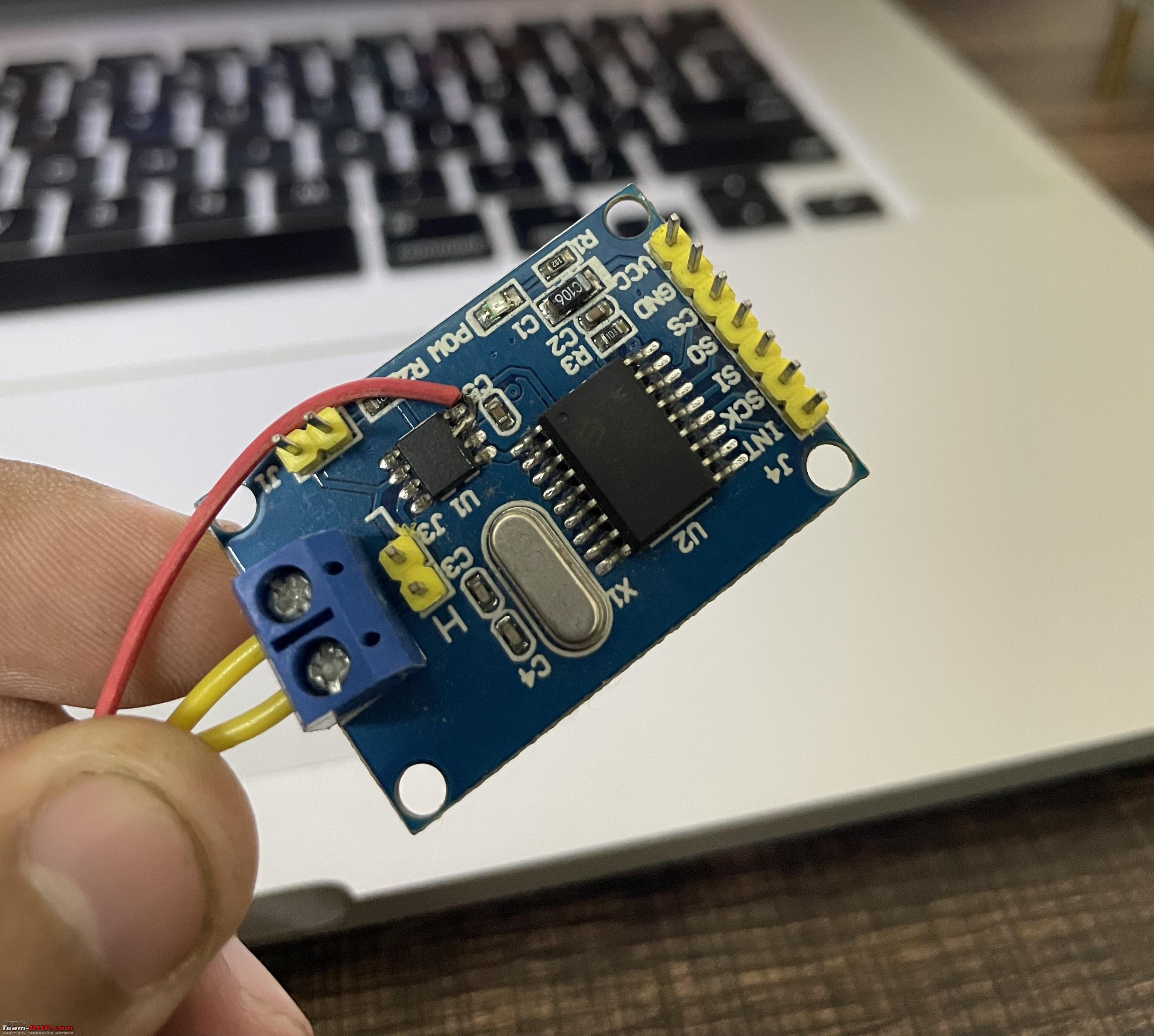 Quote:
Raspberry PI will be an overkill, also it'll never match the boot up speed of a microcontroller. It can be made to boot up faster if gone via the bare metal route, but too much work i'd say. If we go with a Raspberry Pi with a slimmed down version of linux, it'll still take about 5-7 seconds to boot up. Programming will be very easy on a Raspberry Pi though, we could use Python or QT or some other high level language with graphics support. I've started experimenting with the excellent LVGL library running in a bare minimum linux optimised for boot speed on a Raspberry Pi 3B using a 5" DSI screen, its still slow to boot up though. Plan is to create a display showing all of the that will sit in the middle of the dash similar to a BMW iDrive  Good to know that you're also from my place, we could meet someday! Good to know that you're also from my place, we could meet someday! 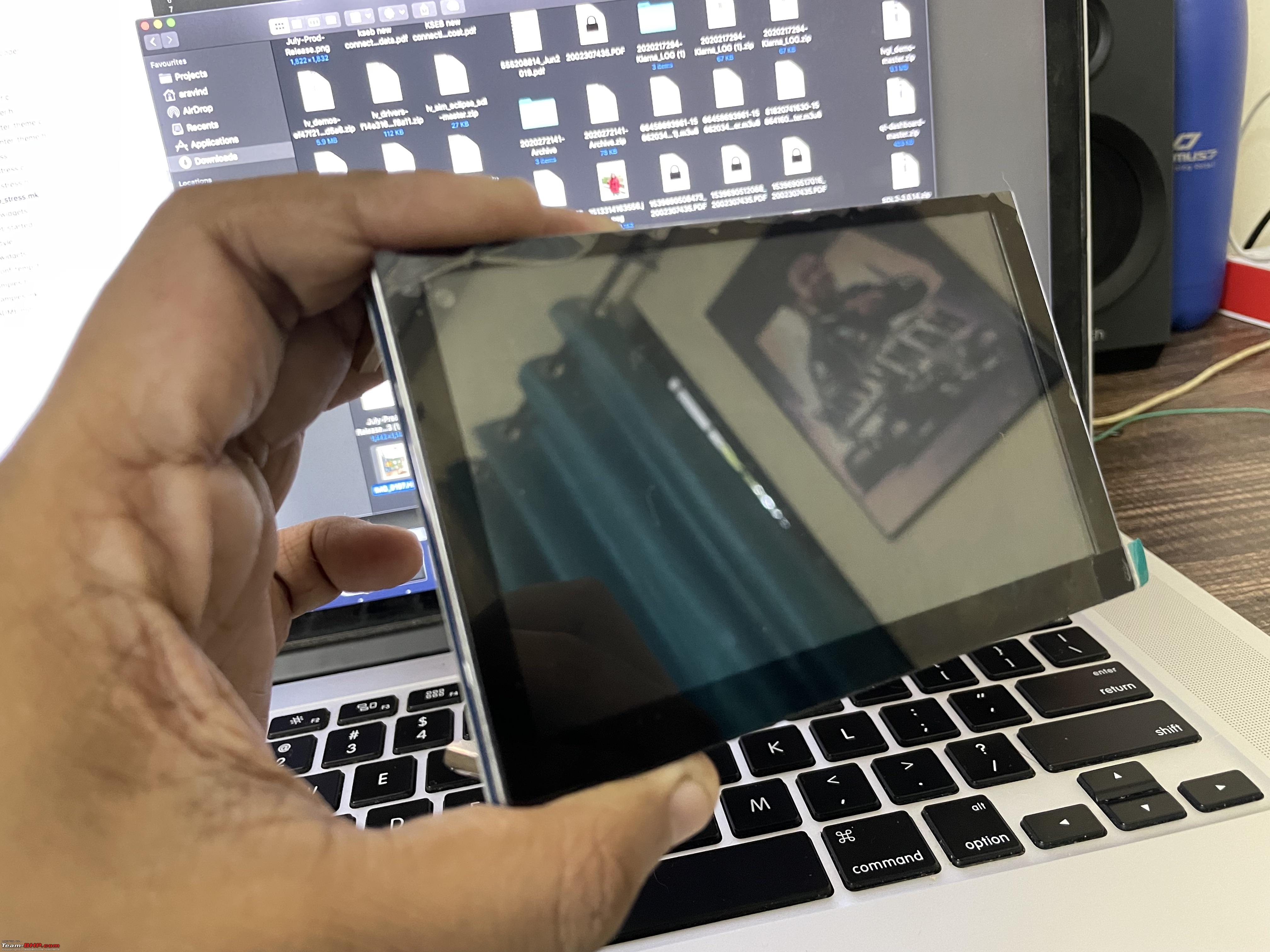 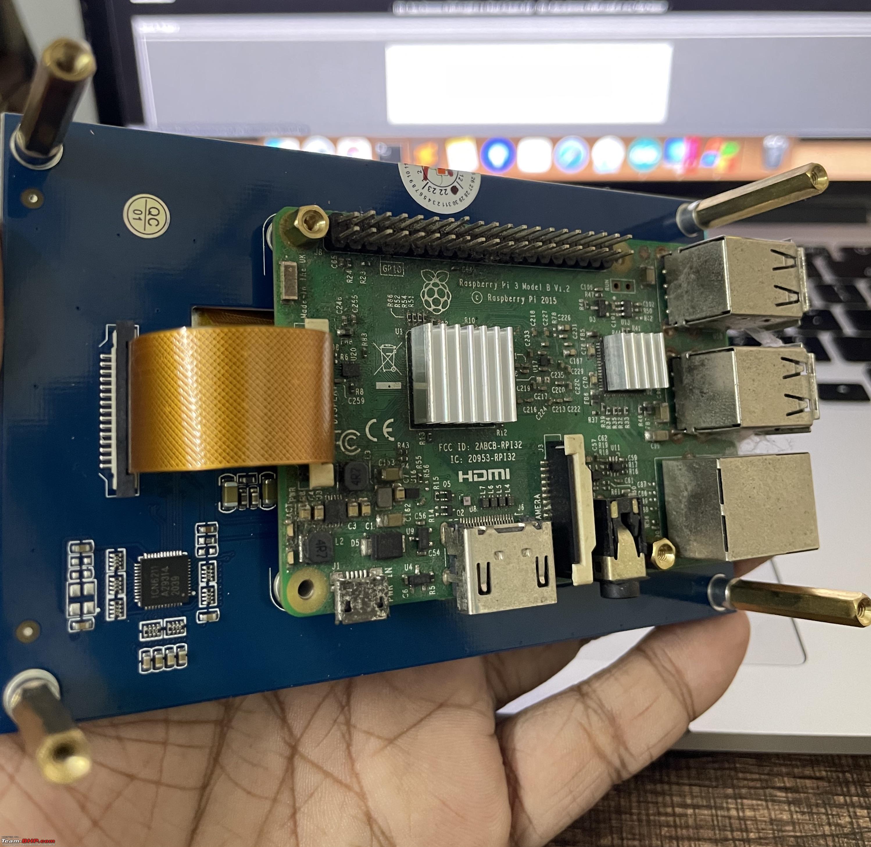 | |||
|
| (11)
Thanks
|
| The following 11 BHPians Thank vsaravind007 for this useful post: | aravindb_0711, ashking101, Gannu_1, jothishX, Omkar, Rehaan, Shubhendra, theexperthand, The_Outsider!, VijayAnand1, vishy76 |
|
19th July 2021, 21:29
| #6 |
| BHPian | Re: DIY: Skoda Laura - Custom Instrument Cluster MFD Display Wow! The number of Technical DIY's are improving leaps and bounds in the forum these days. Amazing mod job though it's in the beta stage. Keep the mods coming and this will make more VAG group owners add this display. One noob question? Can this be installed with the current Instrument cluster available on the Polo? |
|
| (1)
Thanks
|
| The following BHPian Thanks jithin23 for this useful post: | vsaravind007 |
|
19th July 2021, 23:19
| #7 |
| BHPian Join Date: Jan 2018 Location: St.Louis, USA
Posts: 53
Thanked: 61 Times
| Re: DIY: Skoda Laura - Custom Instrument Cluster MFD Display Great work!  as a fellow electronics hobbyist I know this not very easy, this takes a good amount of planning and patience apart from the technical knowledge. Appreciate all your time for documenting it in detail. All the very best and looking forward to see the finished output soon. as a fellow electronics hobbyist I know this not very easy, this takes a good amount of planning and patience apart from the technical knowledge. Appreciate all your time for documenting it in detail. All the very best and looking forward to see the finished output soon. |
|
| (1)
Thanks
|
| The following BHPian Thanks Naveen_0181 for this useful post: | vsaravind007 |
|
20th July 2021, 11:33
| #8 | ||
| BHPian Join Date: May 2015 Location: Trivandrum
Posts: 82
Thanked: 769 Times
| Re: DIY: Skoda Laura - Custom Instrument Cluster MFD Display Quote:
 Quote:
 | ||
|
| (2)
Thanks
|
| The following 2 BHPians Thank vsaravind007 for this useful post: | ashking101, Naveen_0181 |
|
20th July 2021, 12:01
| #9 | ||
| BHPian Join Date: Mar 2020 Location: KL 01
Posts: 64
Thanked: 343 Times
| Re: DIY: Skoda Laura - Custom Instrument Cluster MFD Display Quote:
Quote:
| ||
|
| (1)
Thanks
|
| The following BHPian Thanks jothishX for this useful post: | vsaravind007 |
|
22nd July 2021, 09:31
| #10 | |
| BHPian Join Date: May 2015 Location: Trivandrum
Posts: 82
Thanked: 769 Times
| Re: DIY: Skoda Laura - Custom Instrument Cluster MFD Display Quote:
| |
|
| (1)
Thanks
|
| The following BHPian Thanks vsaravind007 for this useful post: | jothishX |
|
24th July 2021, 20:16
| #11 |
| BHPian Join Date: Mar 2020 Location: KL 01
Posts: 64
Thanked: 343 Times
| Re: DIY: Skoda Laura - Custom Instrument Cluster MFD Display Yes, we can write plugins for torque but I've not taken that route yet. Trying the inbuilt http logging method now |
|
| (1)
Thanks
|
| The following BHPian Thanks jothishX for this useful post: | vsaravind007 |
| |
|
24th September 2022, 01:38
| #12 |
| Newbie Join Date: Mar 2022 Location: Foothills
Posts: 1
Thanked: 0 Times
| Re: DIY: Skoda Laura - Custom Instrument Cluster MFD Display Hey, this is very interesting and I am looking to implement something very familiar. I plan to use the same display as I already have one on hand as well as a few Arduinos and CAN modules. Have you published the code you used for this to Github or somewhere else? |
|
| ()
Thanks
|
|