Dear BHPians,
Today I am trying to give you all a description of mammoth marine diesel engines, which is used in running very large ocean going crude oil tankers. What is the size of the tankers we are dealing with? In an average 300,000 tons dead weight! Yes, 3 lakh tons. (Dead weight means only carrying capacity, own weight not included).
Mods please excuse any mistakes in write ups.
A big thanks to my Junior Engineer Arun, with-out his help it was impossible for me to accumulate all these information. Will try my best to keep it brief and cover most areas.
HISTORY OF PROPULSION ENGINES ON TANKERS IN BRIEF:-
1. With the introduction of large ocean tankers in late 50s, propelling power requirements for tankers went up rapidly, which made way for large steam turbine engines (from small). World War II saw rapid improvement in Steam turbine technology. Hence this was the obvious choice and ready in hand. This type of engine significantly raised weight to power ratio. However they had a major drawback of very high fuel consumption & huge heat loss. Also maneuverability of these engines was restricted. But ship owners stuck with a philosophy of carrying more cargo at one go, thus super tanker market boomed along with steam turbine engines.
2. The reciprocating marine diesel engine first came into use in 1903, but with primitive design, expensive & unsuitable for large tankers. Over the time with improvement in design & fuel economy, they slowly replaced steam turbine engines. Raising fuel cost added benefit to the diesel engines over steam engines (high fuel consumption). Modern large merchant ships use slow speed two stroke engines. Some smaller vessels may use high speed diesel engines. Ships with these engines do not generally need gearboxes. Usually such propulsion systems consist of own direct drive propeller. Over the years these engine claimed astonishing technological achievements.
Few years back (even now on 5 years+ ships) these engines (known as MC engine) digest in an average 80 - 90 mt of heavy fuel oils (IFO 380 cst) to propel these gigantic tankers in laden condition. Though fuel consumption is much lower than Steam turbine engines but with the stricter regulations on SOX & NOX emission it became a challenge for makers to deliver perfect balance of power and fuel economy and also which can comply with emission requirements, especially in ECA (Emission Control Areas). Here comes the ME engine in action.
So what is the special about these new engines (called ME Engines)?
They have to be two strokes with long strokes for massive power requirement, less moving parts for efficiency and use lesser resource, energy loss has been controlled around 22% by various means & utilization of exhaust gas, same lub oil is used for lubricating as well as operating the engine valves with booster pumps, fully controlled by electronics (cam less). Even our senior marine engineers needs to attend a special training program to learn about these engines.
Before I enter the main subject, here is the picture of the engine, to give you the idea of its sheer size. Look closely, two men standing next to it!
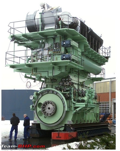
On ship, we call her as Main Engine. Generators are called as Auxiliary Engines. Generators are required for generating electric power, thus four stroke engines are the obvious choice for generators (high rpm). They too run on heavy fuel oils, and also run on marine diesel oils like main engine.
Although our main engine can deliver 41,700 bhp, but it has been de-rated (ECU remap) to produce perfect balance of power, fuel economy & emission. Recently Hyundai Heavy Industry delivered an ME engine with power in excess of 100,000 BHP!
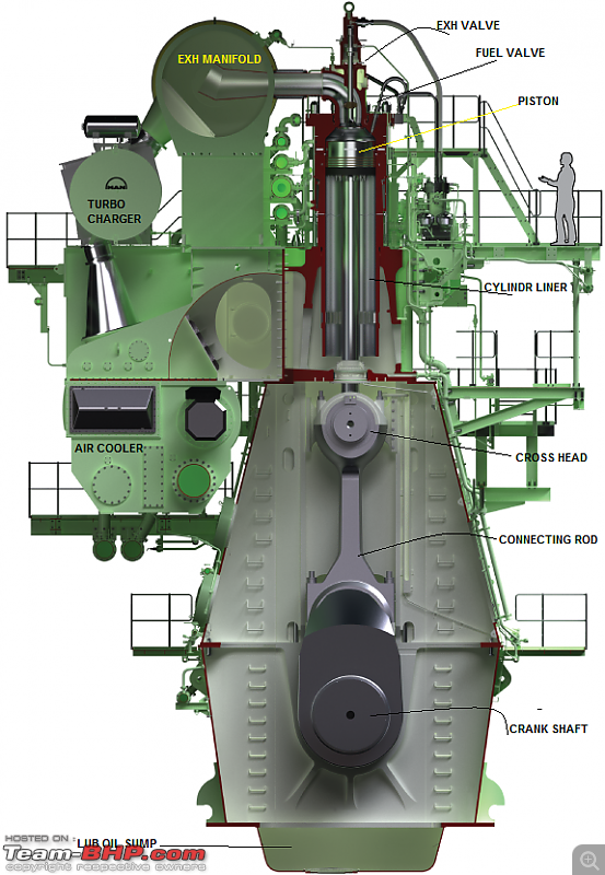
DESCRIPTION OF ME MAIN ENGINE
MAN B&W 7G80ME C9.2 // 24235 KW AT 63.1 RPM
Specification: CMD-MAN B&W // 7G80ME-C9.2 // ENGINE NUMBER: CE 0394A // BORE: 800, STROKE: 3720 // SMCR: 24235 KW AT 63.1 RPM // MEP: 1.76 MPa // Mfg Date: APRIL 2015 // FIRING ORDER: 1-7-2-5-4-3-6 // CLASS: ABS (American Bureau of Shipping).
Let me explain few things here for better understanding:
CMD It is Chinese group of companies, took license for production of these engine in China (CSSC MES Diesel).
MAN, the name it-self - Machinefabrik Ausgburg-Nurember, from Germany
B & W Named after Mr. Burmeister and Mr. Wain
7 7 UNITS
G ULTRA SUPER LONG STROKE (STROKE BORE RATIO 4.6:1) (GREEN ENGINE)
80 BORE IN CM
M - ENGINE PROGRAMME SERIES
E ELECTRONICALLY CONTROLLED ENGINE
C COMPACT (NOW IT IS STANDARD)
9 MARK NUMBER (DIFFERENT Mk No. MEANS DIFFERENT MEP)
.2 FUEL OPTIMISED FOR TIER II ENGINE (.2 MEANS TIER II COMPLIANT ENGINE) (TIER II MAX NOX LIMIT: 14.4 gms/KW-h) 5% NOx(25) + 11% NOx(50) + 55%NOx(75) + 29%NOx(100) < 14.4 gms/KW-h.
FUNDAMENTALS: 2 STROKE CYCLE DIESEL ENGINE 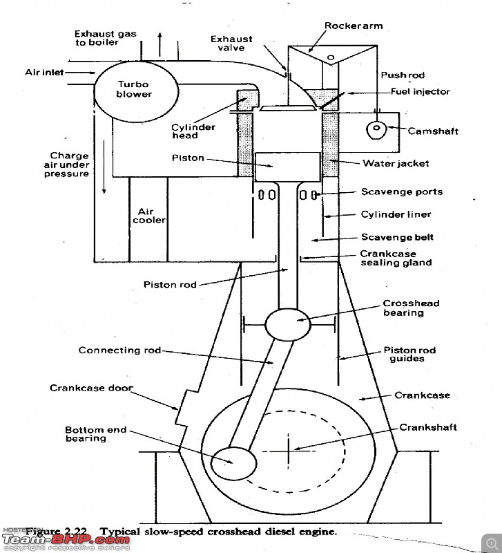
The main propulsion engine on board ocean going cargo ships are mostly of this type. It is named 2 Stroke Cycle because the Cycle is completed in two Strokes of a piston or one revolution of a crankshaft.
In comparison to 4 Stroke Cycle Engine, less time is provided to exhaust gases to leave the cylinder and fresh air to fill in. In 4 Stroke Cycle engine, two separate strokes are provided for this purpose, namely exhaust stroke and suction stroke.
In 2 Stroke Cycle Engine, the function of exhausting of gases and recharging the cylinders with air are carried out between power stroke and compression stroke. These two important functions are carried out in about 120 deg of crank angle in comparison to about 440 deg crank angle for 4 stroke engines.
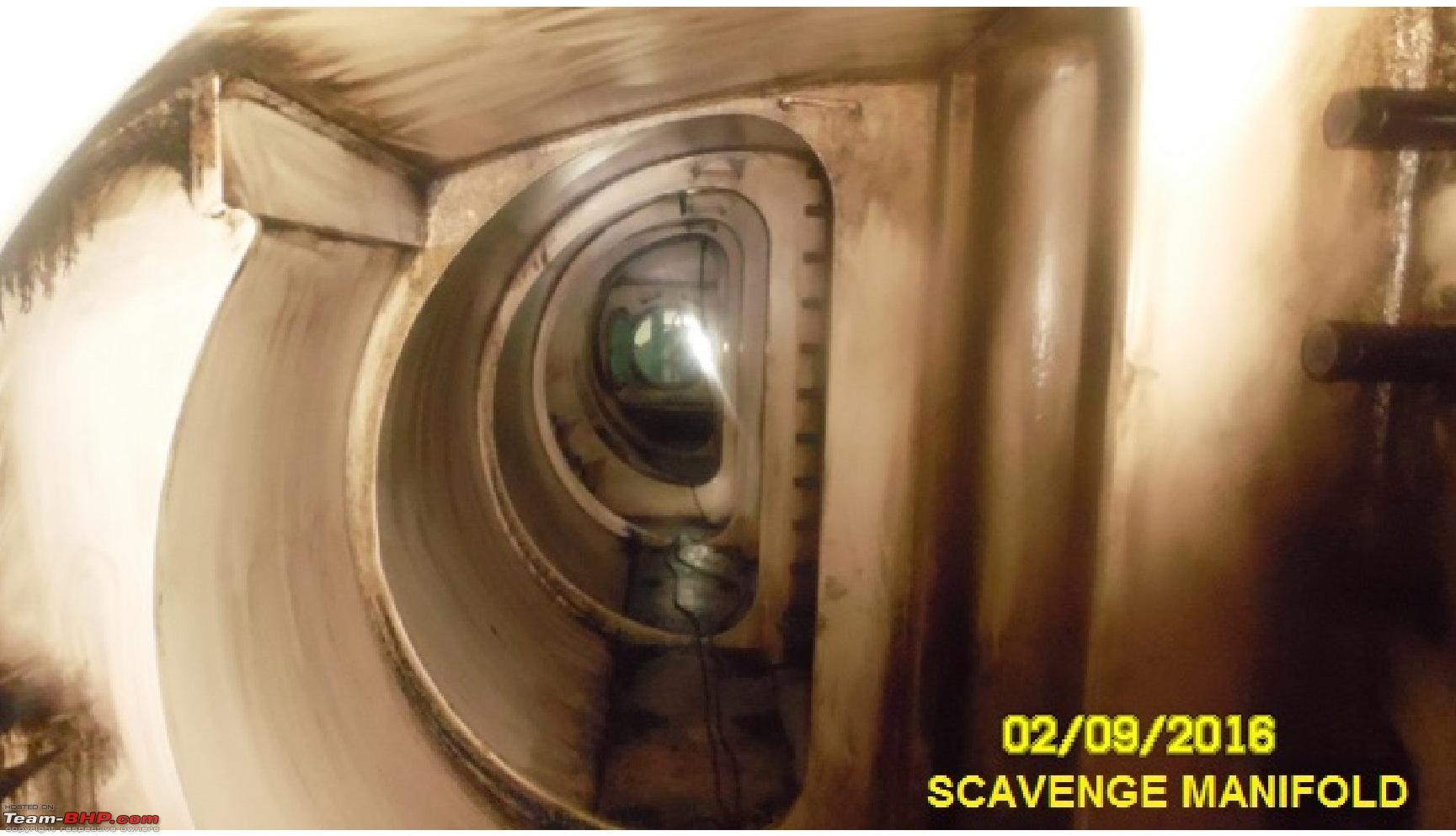
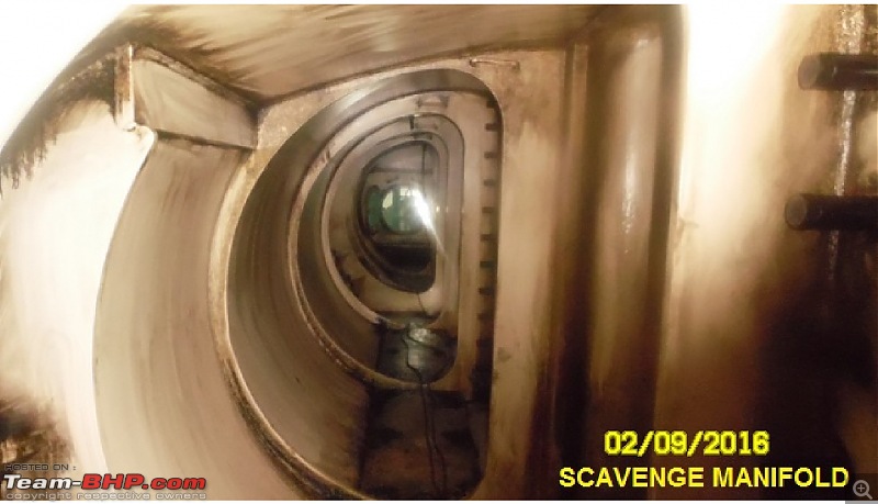
In 2 Stroke Cycle Engine, pistons do not push gases out of the cylinder at the end of power stroke. So, air has to push gases out of the cylinder and make place for itself. In 2 stroke engine, air is called Scavenge air. Scavenge means throwing something out.
In 2 Stroke Cycle Engine (Sulzer or MAN B&W), the air manifold is termed Scavenge Manifold. Whereas in 4 Stroke Cycle Engine (Generator Engine), the air manifold is termed Inlet Manifold.
For engine to operate efficiently, scavenge ports and turbochargers must be maintained in good condition. Scavenge manifold must be maintained at designed pressure, otherwise air will not be able to push gas out.
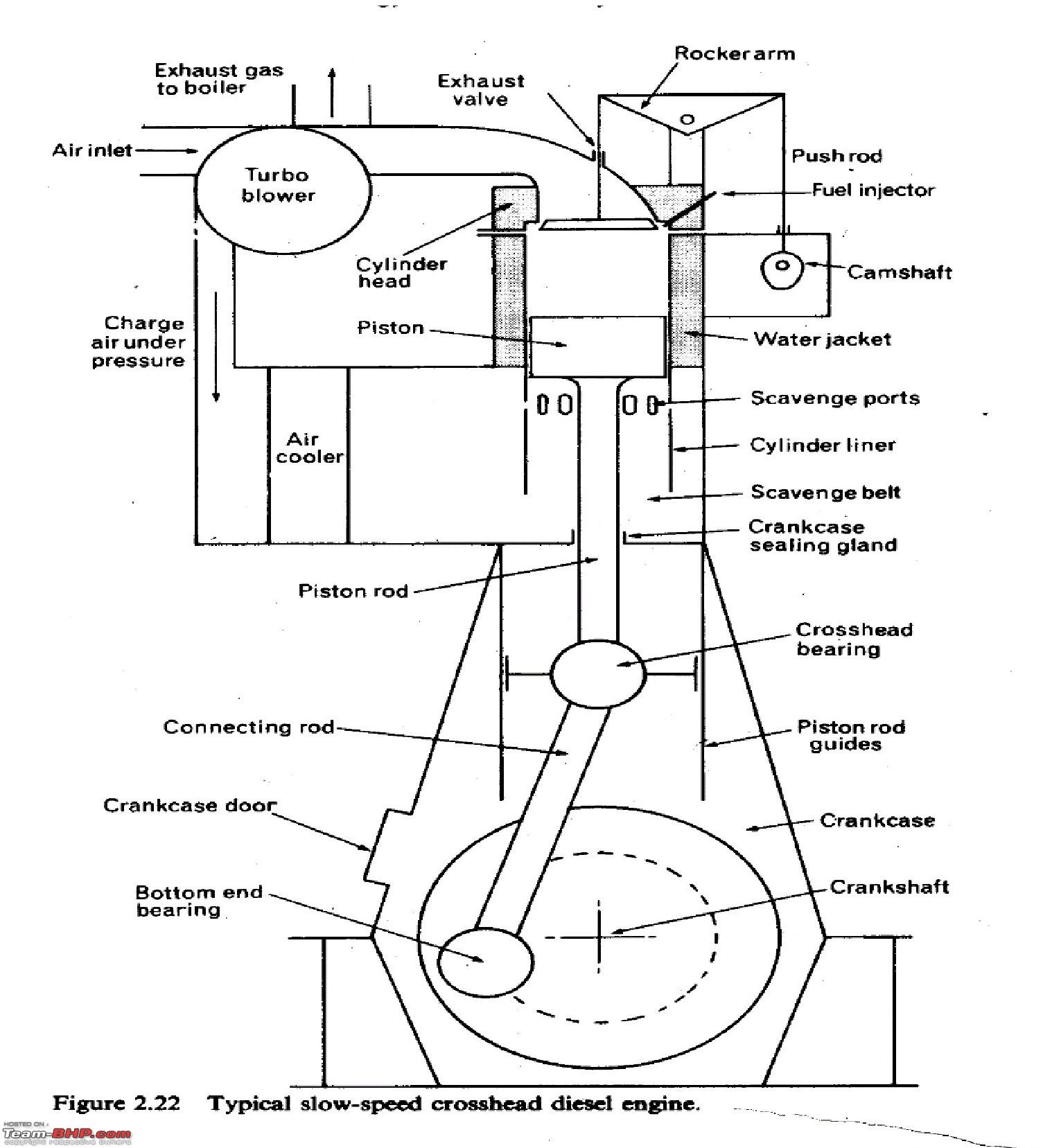
CROSS-HEAD TYPE 2 STROKE DIESEL ENGINE WORKING PRINCIPLE
Compression
In this process, scavenge ports are covered, exhaust valve is close and fuel injector is shut. The cylinder is full of air; air is compressed to about 90 bar and above. The temperature at the end of compression will be about 550 deg C. The fuel is injected (approx 10 deg before TDC) at the end of compression in the form of fine spray.
Expansion Stroke
The pressure in the modern engines go up as high as 140 to 150 bar after combustion and temperature is about 1700 deg C (Note: This is not the exhaust temperature). The hot gases, containing sufficient heat energy do the work on the piston and push towards the end of the stroke. The gases fall in pressure as they expand.
Exhausting & Scavenging in 2 Stoke Engines
There are no separate strokes for Suction and Exhaust. These functions are completed between Expansion and Compression strokes.
Towards the end of expansion stroke (by the time 80% of the stroke is over) exhaust valve in the cylinder head or ports on cylinder are open. Exhaust gases rush out of the cylinder into the exhaust manifold. This happens because of the pressure differential. This is referred to as the blow down period.
Scavenge ports are uncovered by the piston immediately after this stage. Scavenge manifold is maintained between 2 2.5 bar in modern engines.
Scavenge air have two functions in 2 stroke engines: (a) Pushing remaining gases out of the cylinder and (b) Filling up the cylinder with fresh air.
ADVANTAGES OF ME ENGINES:
- Lower SFOC (Specific Fuel Oil Consumption) and better performance parameters thanks to variable electronically controlled timing of fuel injection and exhaust valves at any load.
- Appropriate fuel injection pressure and rate shaping at any load.
- Easy change of operating mode during operation.
- Simplicity of mechanical system with well proven traditional fuel injection technology.
- Control system with more precise timing, giving better Engine balance with equalized thermal load in and between cylinders.
- Lower RPM possible for maneuvering.
- Better acceleration, astern and crash stop performance.
- Integrated Alpha Cylinder Lubricators.
- Up-gradable to software development over the life time of the Engine.
- Good fuel saving at part load.
- Low NOx emission from this type of engines. So environment friendly.
- This engine can also be called as green engine (Stroke / Bore ratio 4.6)
- Ability to run continuously at Super dead slow
- Emission of smoke is very less
- Easy to adjust and balance the engine parameters
- Size of the engine is reduced. It is more compact
- Thermal losses are reduced to less than MC Engines
- It is Tire II compliant engine (Tier IIMax NOx emission limit: 14.4gms/kw-hr)
FOLLOWING PARTS ARE OMITTED IN ME ENGINES FROM MC ENGINES:
1. Chain drive
2. Chain Wheel Frame
3. Chain Box on Frame Box
4. Cam Shaft with Cams
5. Roller Guides for Fuel Pumps and Exhaust Valves.
6. Fuel Injection Pumps
7. Exhaust Valve Actuators
8. Starting Air Distributor
9. Governor
10.Regulating Shaft
11.Mechanical Cylinder Lubricator
12.Local Control Stand
THE ABOVE MENTIONED PARTS ARE REPLACED BY:
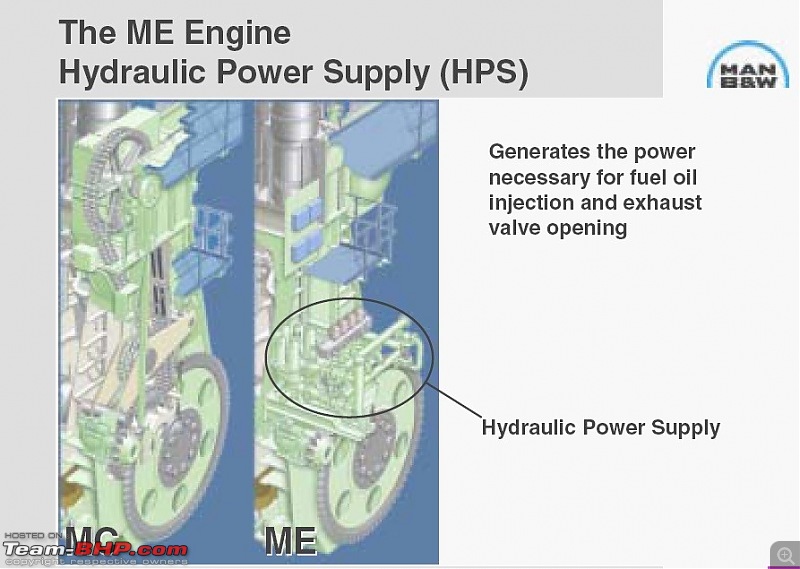
1. Hydraulic Power Supply (HPS)
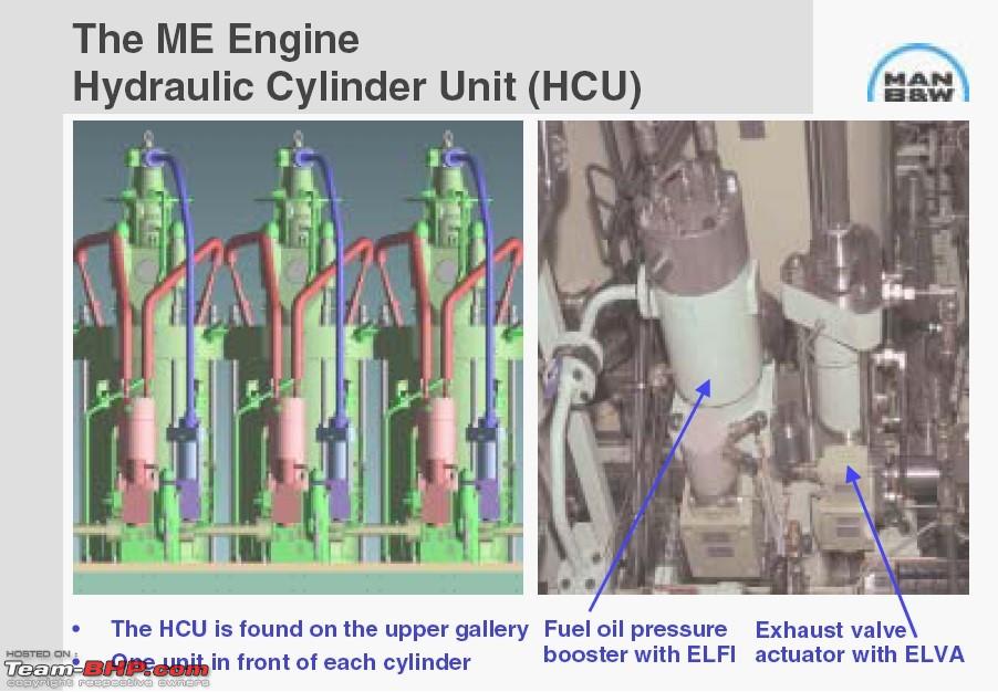
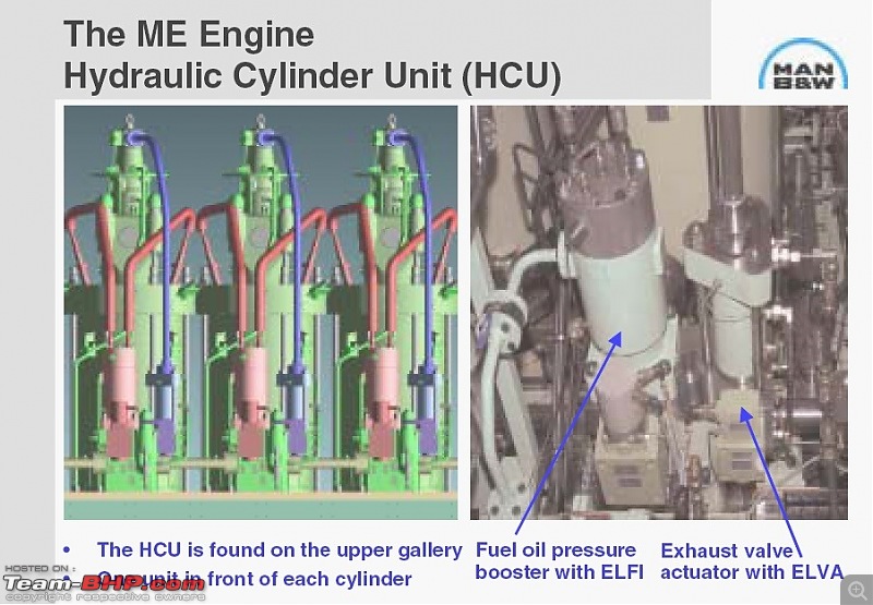
2. Hydraulic Cylinder Units (HCU)
3. Engine Control System (ECS) controlling the following:
i) Electronically profiled injection (EPIC)
ii)Exhaust Valve Actuation
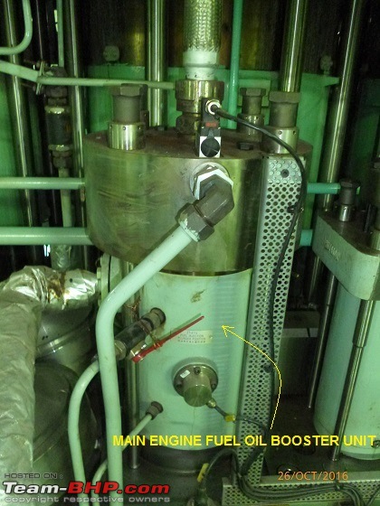
iii)Fuel Oil Pressure Boosters
iv)Start and Reversing Sequence
v)Governor Function
vi)Starting Air Valves
vii)Auxiliary Blowers
4. Crankshaft position sensing system
5. Electronically controlled Alpha Lubricator
6. Local Operating Panel
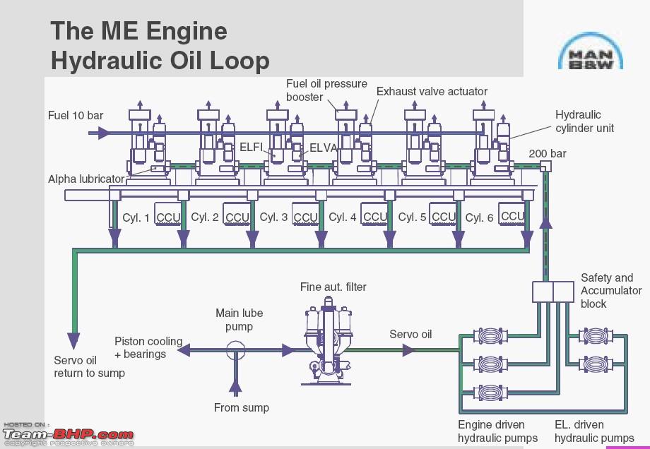
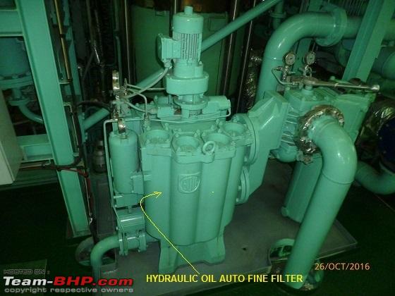
HYDRAULIC POWER SUPPLY UNIT: The necessary power for fuel injection and exhaust valve operation previously provided via the chain drive (MC Engines) is now provided from a hydraulic power supply unit (HPS).
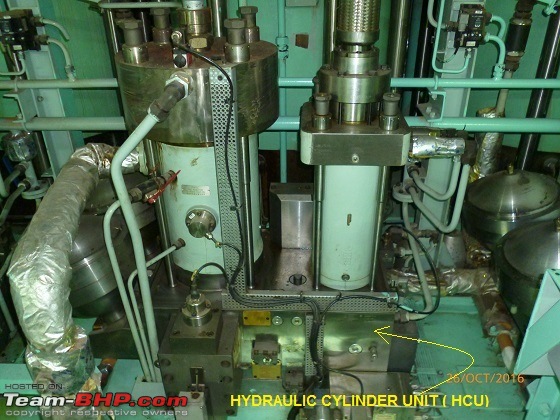

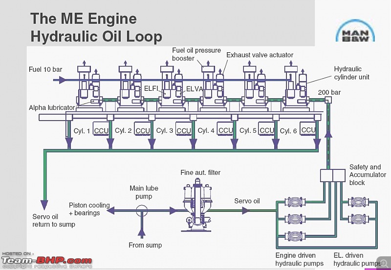
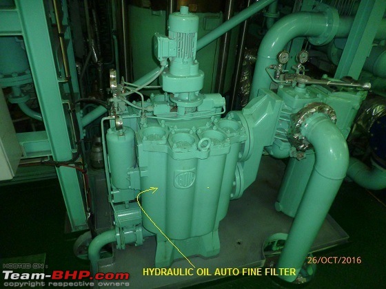
HYDRAULIC CYLINDER UNIT (HCU): In 7G80ME-C9.2 Engine sump oil is used as servo oil (Hydraulic Oil) at a pressure of 200 bars.
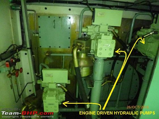
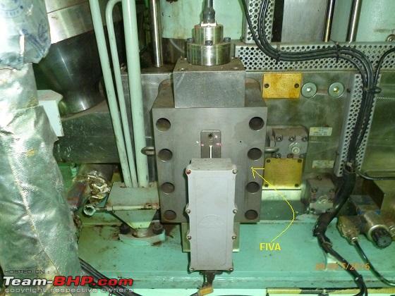
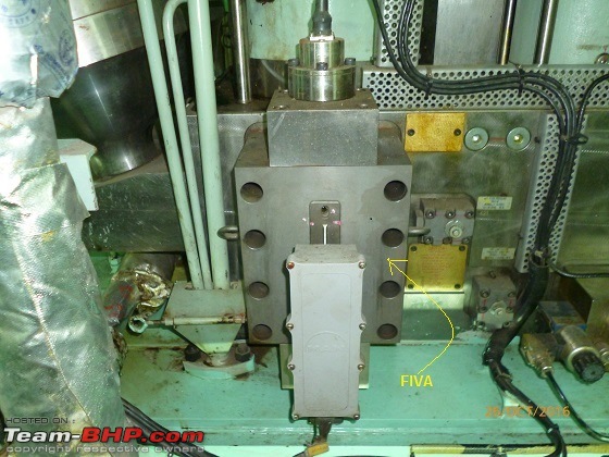
From Main Engine Lube Oil Sump (system oil) Main Engine L.O. Pumps take suction and supplies to engine driven hydraulic pumps through fine auto filter at a pressure of 2.5 bar. This 2.5 bar pressure lube oil now called as servo oil which is pressurized to 200-250 bar by Engine Driven Hydraulic Pumps (3 no). This high pressure oil is supplied to hydraulic cylinder unit for the actuation of FIVA valves (Fuel Injection and Valve Actuation). This high pressure hydraulic oil (servo) operates Fuel Oil Pressure Booster Units, Exhaust valve actuation etc. controlled by Engine Control Unit (ECS).
 GAS EXCHANGE PROCESS
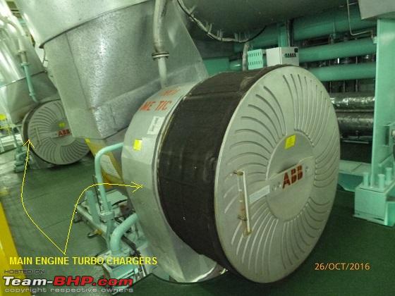
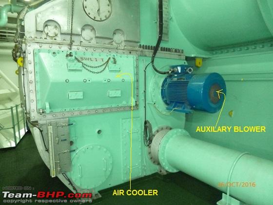
Large mass of air is supplied to the cylinder with super charging process. Our engine makes use of exhaust gas driven turbo charges to supply pressurized fresh air for scavenging and supercharging. MAN B&W 7G80ME-C9.2 also provided with electrically driven auxiliary blowers (these auxiliary blowers start at scavenge air pressure less than 0.4 bar and stop at 0.7 bar pressure) as the exhaust gas driven turbo blowers cannot provide enough air at low engine speeds. Compressed air at higher temperature (above 150°C) is cooled to increase the charge air density. This is done by Air Coolers which are fitted just after Turbochargers. As we know, more the air density is better the fuel oil combustion.
TURBO CHARGING OF ENGINE
Air (around 38 degree temperature) is drawn from the machinery space through a filter and then compressed and then passed through air cooler to increase the air density. Temperature of compressed air is around 150 degree Celsius.

 AIR COOLER:
Our engine air coolers are of tube and fin type air cooler. Where fresh water passes through the tubes and the charge air passes through fins. Temperature of the charge air is reduced from 150 deg to 38-40 deg. From air cooler charge air enters into the scavenge air receiver.
SCAVENGING
As the name indicates scavenging is the removal of exhaust gases by blowing in fresh air. There are two basic type of scavenging process in use on slow speed two stroke engines.
- The cross flow scavenging
- The uni-flow scavenging
Engine 7g80me-c9.2 equipped with uni-flow scavenging where the incoming air from scavenge air receiver through liner ports located at the bottom of the cylinder liner helps in scavenging of exhaust gases, efficient combustion of the fuel. Uni-flow scavenging is most efficient scavenging process than the other processes.
 FUEL OIL SYSTEM OF ENGINE
Engine 7G80ME-C9.2 is usually arranged to operate continuously on heavy fuel (IFO 380 cst) and have available LSMGO (Low Sulfur marine gas oil) supply for maneuvering conditions in ECA (emission control areas) where we cannot use fuel oil more than 0.1% sulfur content.
FUEL SUPPLY SYSTEM
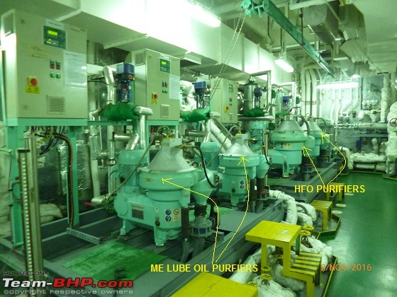
Initially Fuel Oil is stored in bunker tanks. We have 4 bunker tanks in total in varying sizes. Here oil is maintained over 40 deg C. First step of purification takes place here, allowing high density water to settle down. Then it is taken to one settling tank and heated around 80 Deg C to remove remaining water & sediments. Then the oil pumped to purifiers through purifier feed pumps.
PURIFIERS works on the principle of centrifugal force separation. Removal of sludge and water content of the oil takes place in purifiers and the oil is pumped to daily service tanks, from where it is used in engine. Total bunker capacity of this ship is mammoth 6,412 m3. With that she can travel for almost 95 days without refueling and cross close to 29,000 nautical miles. But this is not the case most of the time, as we dont mix bunkers of different origins due to compatibility issues. Thus all bunker tanks are not empty or full always. Means there will be one or two tanks each with different fuel oils. Every time we receive a bunker, samples are sent ashore to a laboratory for analysis and to ascertain any special precaution require to use this oil, like purifier setting, inject temperature requirements, sulfur content, presence of any harmful chemicals etc.

 STARTING STOPPING REVERSING MAIN ENGINE
Unlike car engines, you just cant start these marine engines on the go. One needs to follow certain procedures.
Before the engine can be started, we need to prepare the engine well in advance. However with strict terminal / port regulations now a day, our engine is kept always ready & warmed up. Warm up is a big factor here.
Followings are small list of preparation: (there is a check list available!)
Fuel oil warm up / line up including pumps / purifiers
Switch on all cooling water / lubricating pumps
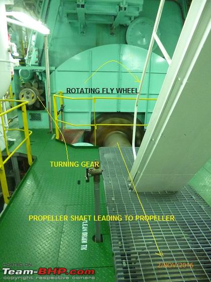
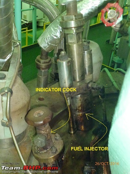
Obtain propeller clearance (just to ensure no small boat is close to the propeller area), and engage the turning gear and turn the engine by means of turning gear with indicator cocks open to ascertain that nothing obstructs the movement of the running gear, at the same time operate the hand cranks of the cylinder lubricators for about 20-25 turns so as to ensure satisfactory lubrication of the cylinders from the very beginning. Disengage turning gear.
Check starting air reservoir for correct pressure is being maintained.
Then blowing through the engine by means of compressed air. This is kind of simulation of starting. This is done to remove any moisture from the combustion chamber. Also this procedure ensures correct operation of all the inlet / outlet valves & actuators.
Once all above is satisfactory, control is given back to bridge and we can start the engine. Engine always starts with air & then automatically fuel is injected.
It is very important to monitor all parameters closely at every initial stage.
Stopping:-
While navigating at sea we just cant stop the engine, unless there is an eminent danger or to save the ship / our lives. There is a function called Crash Astern, which is only used to stop her immediately in grave danger. But just to tell you, in my 22 years of sea life, I never saw this is being used once.
To start / stop the engine at will, we required certain status on engine which is called maneuvering or Standby. By which engine rpm is brought down below certain rpm, an additional generator is switched on for extra power consumption from auxiliary blower & boiler etc and lots of other machinery adjustments are also requires. We have pre-planning, meeting to decide when we require the engine to operate in maneuvering mode.
Reversing
Reversing of the engine is performed electronically and controlled by the Engine Control System, by changing the timing of the fuel injection, the exhaust valve activation and the starting valves. Engine can be kicked astern from stop position anytime; however with crash astern command, engine wont start astern, till the time engine rpm is below certain ahead rpm. For example on this engine that ahead rpm is 16.
MAINTENANCE, SPARES & MONITORING
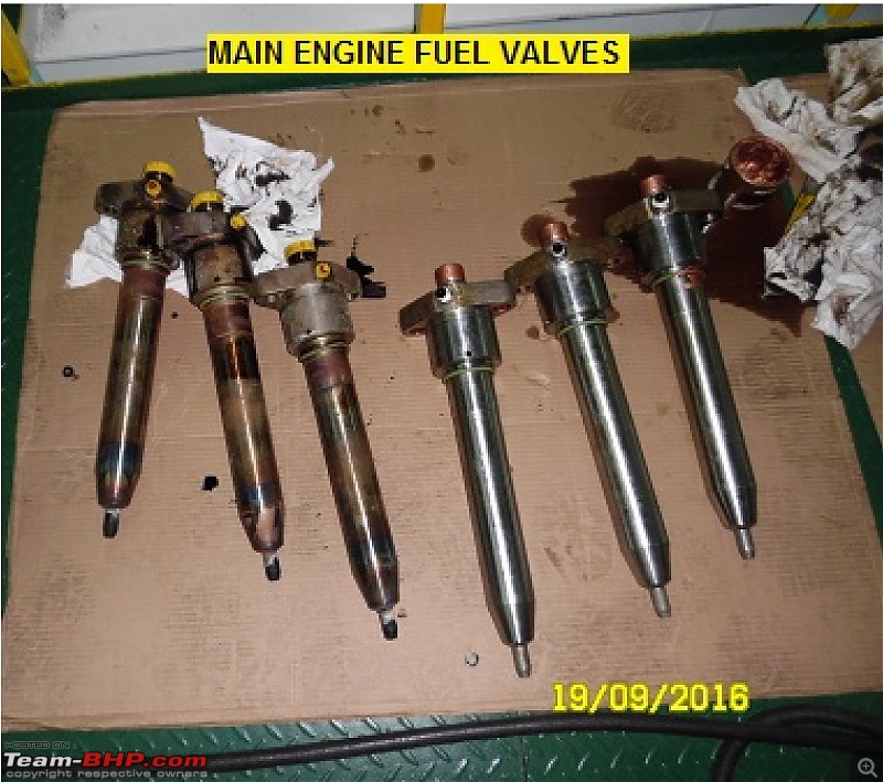
There are several sensors continuously monitoring all parameters. Any deviation immediately triggers an alarm and duty engineer attends / solves the issue. If the deviation is severe or serious in nature, the alarm goes to all engineers cabin. All the engine component has a specific running hours, after which it requires: inspection / measurement / monitoring / replacement. Most of the critical spares are carried onboard, namely: one/two Piston, one cylinder liner, couple of exhaust valves, important pumps, fuel injectors, various sensors, T/C spares etc. Remaining spares needs to be ordered well in advance in-line with maintenance schedule. Sometime the lead time for spares may go up to 3-4 months from maker. Every month while running at sea, main engine is run at a higher rpm for 2-3 hrs irrespective of ordered speed. This is required to compare engine performance data along with shop-test & pre-delivery sea-trial performance. Data is closely monitored for any deviation outside tolerance limits. If any problem found, office technical department is notified, the part is identified & immediately replaced. Also now a day, daily engine parameter/performance is automatically transmitted directly to the Owners via email, where we cant access these emails/data.
Lastly big thanks to our engineers, they needs to be skillful in mechanical + electric + electronics & in hard-work department. These ships are monitored by charterers via satellite (like GPS tracking). Any breakdown to the engine / stoppage means a big hole in Owners pocket, as charterers will not hesitate to deduct freight from owners. However I still hold some tricks in my sleeve to save my owner when time comes.
There is no end to write up on this magnificent human art. But I think any more information will make this thread boring. Since I am not an Engineer, I may have missed out few things. Do let me know if you need any clarification.
Here are some pictures to end this post.
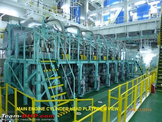
E/Room ME Cylinder Head Platform 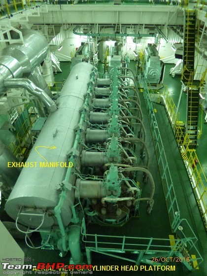
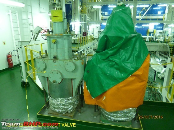
 Massive spare piston
 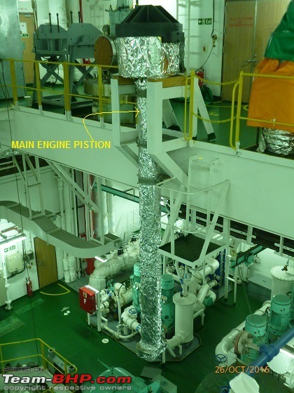 Exhaust Valve
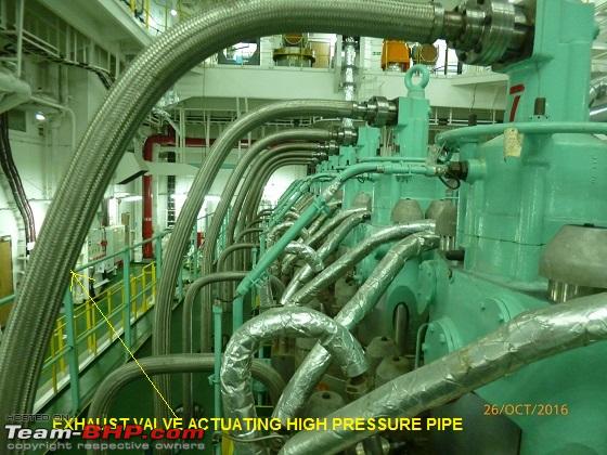
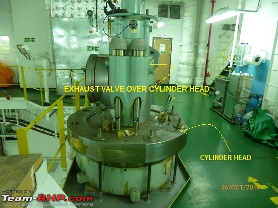
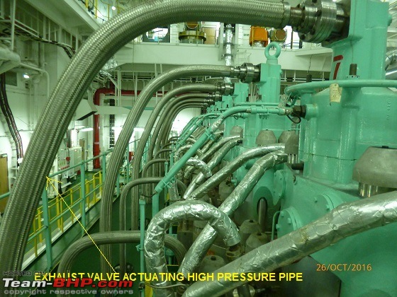 Exhaust Pipe
  Engine Control Room
 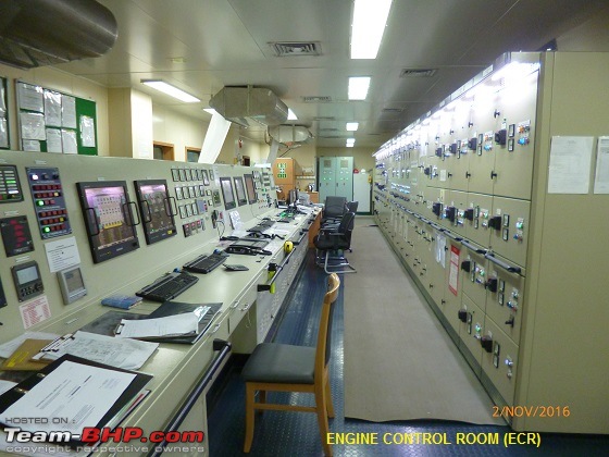 The Prop shaft
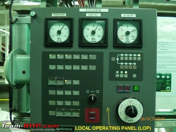
 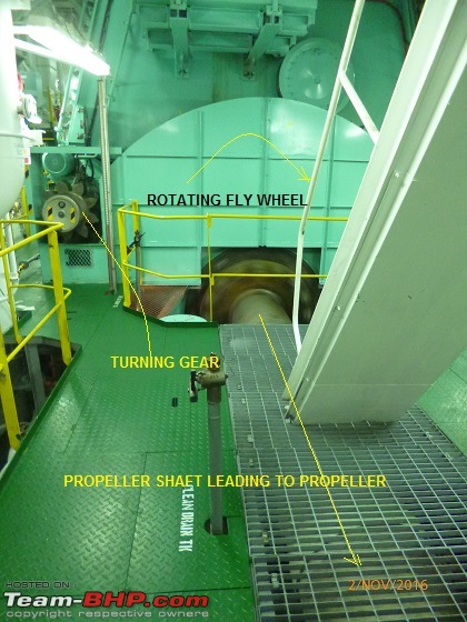 Local Operating Panel
 (in case of electronics failure on bridge/ECR)
 Bridge Telegraph
 (from here engine command is given)

Thank you, Sail, for the wonderful post.
So the engine displaces ~12942 litres! :Shockked:
Does it even matter? stupid:
Very nice. One thing I've noticed is that it is common to have odd no of cylinders in marine engines, with 5 & 7 very common.
Rahul
The very best of Team BHP. Thank you for the time and effort to pen this down for our benefit. Rated it a well deserved 5 stars. These are mechanical marvels. I had no idea there was so much of cleaning of the oil before ignition. - Narayan
How I wish to work in these moving palaces called ships? It is an enigmatic feeling to read anything about the naval vessels and the engines are the best part of them.
Excellent article about the engines. Thanks for sharing.
Quick question, who holds the biggest of marine engine business share?
MAN, Wartsila or Cat?
I doubt anywhere else on the web would we get such an elaborate narration by someone who actually works with this stuff day-in & day-out!
One of the very best posts/threads on TBHP :)
Thanks for posting such a wonderful article. It couldnt have come at better time as I was preparing for a seminar on 2 storke diesel engines :)
Thanks for sharing, very nice thread. I started my career in the (merchant navy) and ended up as Chief Engineer. Quite some time ago, so I have never sailed with anything as modern as this here.
Very interesting to see these developments. Couple of thoughts / add ons.
In my days, just about all merchant ships, even the ones running diesel engines had steam boilers as well. As you wrote originally most of the very large ships, in particular (super) tankers. (VLCC, ULCC) had steam propulsions. However, the steam was also used/necessary to heat the large, i.e. crude oil in the holds!
On the diesel powered ships I sailed on we also had steam boilers for several purposes. Its most important purpose was to head the heavy fuel we used. The whole fuel system is heated, depending what kind of fuel could be up to 80oC. Also, the fuel tanks had heater coils for the very same purpose. Next the boilers provided heating of various other things, such as accommodation, provided steam for the laundry!.
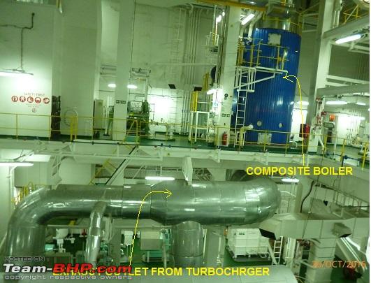
On the ships fitted with slow speed 2 stroke engine, the boiler was often a so called exhaust gas boiler. The exhaust gasses of the engine could be diverted through the boiler. When the main engine wasnt running, or not running under sufficient load, it used conventional burner to keep it going.
These sort of boilers were relatively simple. For heating purposes you dont need superheated steam, so pressures and temperatures were moderate compared to boiler systems used for (steam turbine) propulsion.
On some of the last ships I sailed on, we had so called themal boilers. Basically a thermal oil was heated in a boiler and was pumped around to whatever needed heating. Pretty simple, much more reliable and very little maintenance.
I would be interested to hear/learn what sort of heating systems are used these days.
No doubt the 2-stroke slow speed is the King when it comes to power. But dont knock the current 4-stroke medium speed engines either! The most powerful ones produce well over 55.000 Horsepower these days.
From a ship design point using a slow or medium speed engine is pretty fundamental. There is the obvious difference in size. On a Supertanker or say a bulk carrier you can fit a slow speed engine right at the rear of the ship where the superstructure is. But on say, a ferry, rollin/roll off or cruise ship a medium speed might be advantageous as they are so much lower.
Whereas the low speed engine will drive the propellor shaft directly the medium speed engine will always require a gear box. Expensive!
Medium speeds engine run on heavy fuel as well, so they also need all the same fuel heating, treatment, filtering system as the slow speed ones. Although, at least in theory, the slow speed one can take even heavier fuel.
These heavy fuels do lead to higher maintenance, wear and tear. I have worked for several shipping companies who went from heavy fuel back to regular fuel for all their medium speed engines. The additional cost and some other issues, outdid the lower cost advantage of the heavy fuel.
You mentioned that you cant just stop an engine from going full ahead to stop due to the (heat) stresses on the engine. Its true for any engine, but typically the bigger, the more of a concern this is.
On most vessels there will be different full ahead. There is a full ahead that is used during manoeuvring. Safe to stop the engine, reverse, go forward etc. Then there is cruise full ahead. Basically you will have to slowly increase RPMs to reach maximum and slowly decrease RPMs back to manoeuvring full ahead.
To give you an example; On the last 2-stroke slow speed ship I sailed it took two hours to go from manoeuvring full ahead to cruise full ahead. The difference:
- manoeuvring full ahead 85 RPM
- cruise full ahead 120 RPM
I remember one trip. We had left from Singapore and once we were done manoeuvring and there was sufficient sea room the order was given to to 120 RPM. The 5th engineer was on watch. We were all in the messroom. Now on this particular ship at 100RPM there would be a slight vibration and it would show in some plants in the messroom. We noticed that the plants started to vibrate! So we run downstairs into the engine control room, pushed the 5th engineer out of the way and reduced RPMs. However within hours it became apparent that major damage had already been done! We had to pull two cilinder linings. One needed replacing as it was cracked. The other one, lucky for us, was not cracked but the seals for the cooling water were damaged.
Interesting job, doing this on a pitching and rolling ship!
The steam ships took a long time to start up. But even on a diesel ship, especially with heavy fuel it could take more than a day. If you started from a real dead ship, no electricity, no air, here is how it went:
You made your way into the engine room with torches. Always two people for safety with more people standing by outside the engine room.
first things first, get some electricity going! That means you need to be able to start a dieselgenerator. Usually these are started with compressed air.
If there was no air pressure left, first you have to either manually pump up a small air vessel. Start a small diesel engine driven compressor. Use that to fill the main air vessels. Once you had enough pressure in the main air vessels you can start a dieselgenerator and bring it on line. Until that moment you could have been working in the pitch dark with only your torches.
Ones you have the generator on line, you will start to bring all other electrical equipment on line as well. Depending on loading you might have to add more dieselgenerators.
In my days, the next thing is to start up the boiler, because you need steam to heat up the fuel, the lub oil etc. So that could several hours. Once you have steam you bring the various systems on line. You start up the fuel and lub separators, start circulating fuel and lub through the engines.
Fuel, lub oil, you might want to pre-heat cooling water too. It will take several hours for everything is up and running at the correct pressures and temperatures.
In my days we did not have much automation. So it involved running around the engine room, climbing stairs up and down, throwing switches, opening/closing valves etc.
Once the fuel, lub oil and cooling water have the correct temperatures you would start switching on their respective main circulation pomp, check the heat exchangers, check pressures etc.
One hugely important function of the turning gear on the main engine you mention is to turn the engine one full turn, prior to first start. Every cilinder head has a small valve fitted to it. These valves were opened up during this turn. Whilst turning one of the engineer would check no water or lub oil would spew out! It really ensured that the engine could turn freely and there had not been any internal leaks into the cilinder. If you would start such huge engine with any liquid on top of the piston you would have major, major engine damage upon starting!
So after the one turn by means of the turning gear, the turning gear would be disengaged, main air vessels air starting valves would be opened and you would be ready to start main engine. There is several hundred other details that need doing/looking after. But I hope it illustrates the complexity of starting up a large vessel.
Ill see if I can dig up some of my (very) old photographs on these engines.
Jeroen
Jeroen