Team-BHP
(
https://www.team-bhp.com/forum/)
Hello people,
Can anyone here give a step by step guide on how to set this led thing up. I have a santro, really want to do this thing in my car on my own. But, I have absolutely no idea how to go about it.
Please help! please:
Abhi
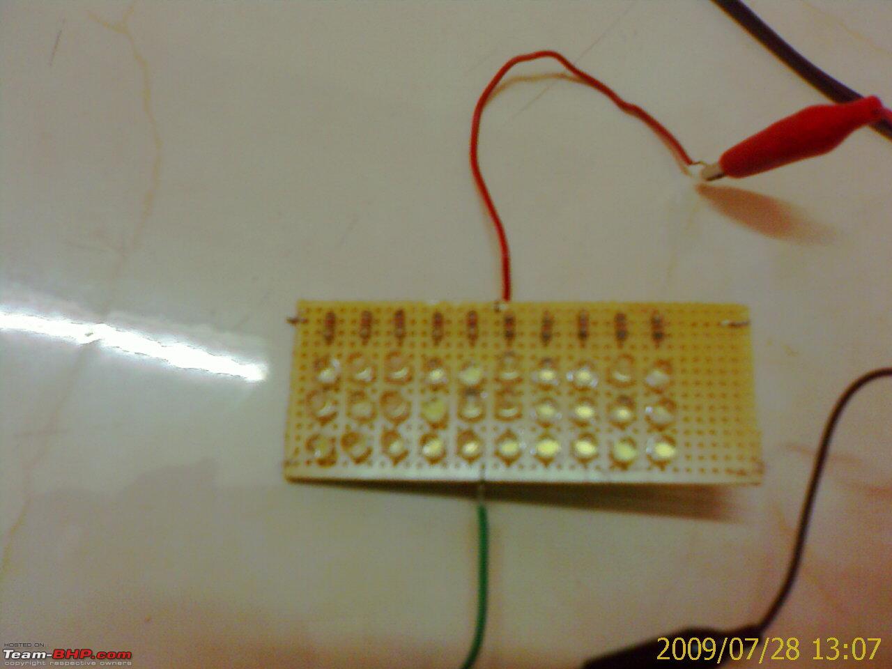
1. find out an electronics spares shop
2. things you'll need -
a) soldering iron
b) solder
c) snipper ( to cut off leads) or any equivivalent tool
d) dot PCB
e) white LED's
f) 100 Ohm resistors.
3) solder them according to the circuits you see us discussing in this page :)
@Gopinathann : Is it possible that in the process of your experiment, you managed to short one of those circuits? Just wondering. Replace one of those non-working branches with new LEDs and check if they glow.
Quote:
Originally Posted by greenhorn
(Post 1405346)
1. find out an electronics spares shop
2. things you'll need -
a) soldering iron
b) solder
c) snipper ( to cut off leads) or any equivivalent tool
d) dot PCB
e) white LED's
f) 100 Ohm resistors.
3) solder them according to the circuits you see us discussing in this page :)
|
Thanks greenhorn,
Will surely follow up on circuts and do it on my car.
Thanks again,
Abhi
Quote:
Originally Posted by benbsb29
(Post 1405366)
@Gopinathann : Is it possible that in the process of your experiment, you managed to short one of those circuits? Just wondering. Replace one of those non-working branches with new LEDs and check if they glow.
|
Could be the problem, I will check that. Thanks.
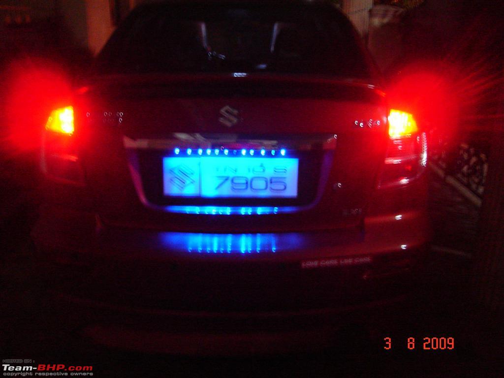
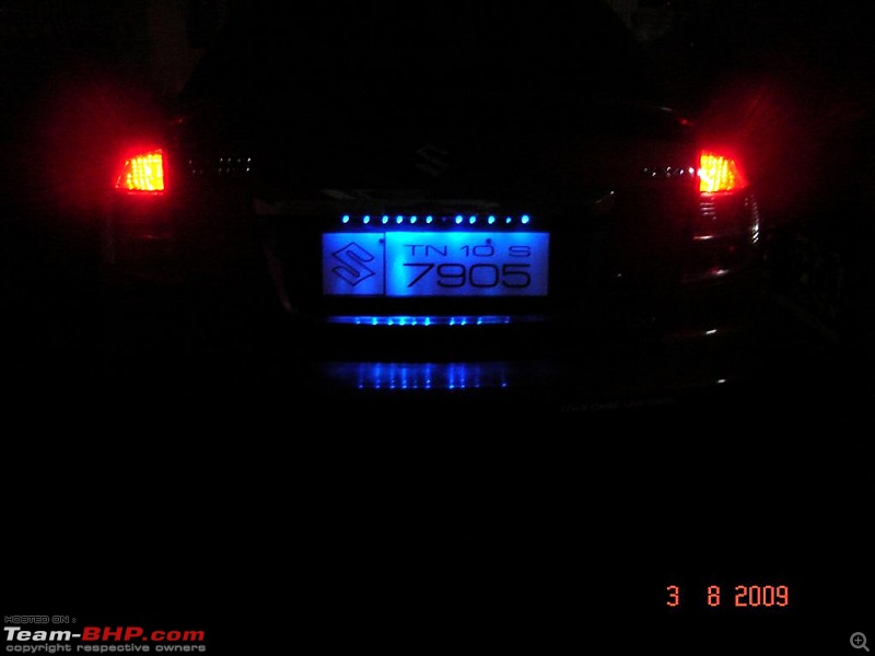
Added blue LED strip for the number plate. Looks bright in the night.

Quote:
Originally Posted by greenhorn
(Post 1405346)
1. find out an electronics spares shop
2. things you'll need -
a) soldering iron
b) solder
c) snipper ( to cut off leads) or any equivivalent tool
d) dot PCB
e) white LED's
f) 100 Ohm resistors.
3) solder them according to the circuits you see us discussing in this page :)
|
Also a simple digital multimeter will be handy .
I use a 'nail cutter' to cut the leads off, instead of snipper/cutter etc. Works well.
Quote:
Originally Posted by shyamhegde
(Post 1414855)
Also a simple digital multimeter will be handy .
|
+1 to that. The slight current from the multimeter is enough to produce a faint glow to identify the colour of the LED (If you have mixed the different colour LEDs together)
from my experience with my DMM ( 'UNITY' brand), this works with only red and green. not too sure about white and blue, since their threshold voltages are higher
Quote:
Originally Posted by greenhorn
(Post 1416510)
from my experience with my DMM ( 'UNITY' brand), this works with only red and green. not too sure about white and blue, since their threshold voltages are higher
|
Yes , DMM will not work with blue and white LEDs.
If you are people are into DIY - build a variable power supply - those using LM317 - very useful.
If you can't build one - you can get a variable voltage mains adapter from market - it has output from 1.5V to 12V in steps of 1.5V. Should not cost you more than 150 bucks IMO. Try local repair shop - if they don't stock, ask them to procure one from market.
Or else you can get the kit from here (they are costly IMO):
[Aplus] Tiny 1.2 - 30V Regulated Power Supply - Lynx Chandigarh Largest Electronic & Computer Online Superstore In India
You really dont need to build any adapter actually, Any DC source like a mobile charger/modem/router adapter etc can be used along with an appropriate value resistor :)
Guys, what do you use to cut the dotted circuit boards? I bought a few to use, but trying to cut them to size has left me flumoxxed. i was thinking of getting an axe-saw blade for the same. Hope that works.
Quote:
Originally Posted by greenhorn
(Post 1416835)
You really dont need to build any adapter actually, Any DC source like a mobile charger/modem/router adapter etc can be used along with an appropriate value resistor :)
|
Yes that can be done. A mobile charger which has 5v output can be converted to 3.5V by adding two forward biased silicon diodes in series like 1N4001/4007 (two silicon diodes in series with create a voltage drop of 1.4V). Current output will be limited to 1 Amp. IMO this is better than resistors.
Quote:
Originally Posted by benbsb29
(Post 1417033)
Guys, what do you use to cut the dotted circuit boards? I bought a few to use, but trying to cut them to size has left me flumoxxed. i was thinking of getting an axe-saw blade for the same. Hope that works.
|
Use a small hacksaw. A small one with blade and handle can be obtained from hardware stores. Get one with fine teeth - tell them it will be used to cut aluminum channel. You can get one for around 50 bucks.
I just make two cuts at both sides of the dot PCB where i need it to break, and then break along the dotted line, exerting pressure with my thumbs at the region near the cuts :D
file the sides by rubbing on a concrete wall if required :p
| All times are GMT +5.5. The time now is 21:47. | |