Team-BHP > Technical Stuff > DIY - Do it yourself
Register New Topics New Posts Top Thanked Team-BHP FAQ


Reply
  Search this Thread
58,829 views
Old 1st April 2009, 13:32   #16
BHPian
 
ilangop's Avatar
 
Join Date: Jul 2008
Location: Chennai
Posts: 992
Thanked: 903 Times

Quote:
Originally Posted by adheesh View Post
Hi ilangop !

Congratulations on you success !! Could you please post the wiring diagram and the modifications done to the bajaj tacho

Regards,
Adheesh Parelkar
Thanks Adheesh.
Plz scroll down to the last 4 pictures from my first post. The circuit borad is shown there. There are 3 screws connected to 3 lugs. On the other side of the board its written like "IGN", "GND", & "SIG" for ignition, ground and signal respectively. Connect "IGN" to key on. In my case the 118-NE's fuse box had an unused pin where I had connected. Alternatively the brake lamp switch is another accessible point for 12V. Its better to connect it through "Key-On", rather than dirst 12V. "GND" is simply body gnd.
"SIG" is where you need to feed in the pulses.
Refer to figure below. Locate the point marked in red in your petrol vehicle. Connect "SIG" to this place.

If you intend to go for a Bajaj Tacho, there was a 220K present and a 330K resistor in series connected to the last 2 pins of the driver IC. One of the pictures in my previous posts shows a small blue coloured box type component. Thats the preset. (Please ignore the explanation on preset if I had under estimated your electronic expertise) The IC is numbered "CS8190" an universal air core coild driver used in many speedo and tacho applications. Download the data sheet and just go through the documentation. You can easily calculate the Resistors as per the needle movement required for you. Hope I have made you clear.

The attached picture is for a contact breaker ignition system. But the same principle applies to any type of igntion systems be it a CDI or the one controlled by ECU.
Attached Thumbnails
DIY tacho for a car, using a bike's tacho-cb_ign.jpg  

ilangop is offline   (1) Thanks
Old 1st April 2009, 22:30   #17
BHPian
 
adheesh's Avatar
 
Join Date: May 2007
Location: Bombay
Posts: 526
Thanked: 53 Times

Thanks a lot ilangop. You would be happy to know that I would be trying this project on your car model's (118 NE) sister car ie. Premier Padmini ! I plan to go one step ahead and also add the dwell meter functionality (which would aid in perfect ignition system tuning) in addition to the tachometer using the same apparatus from Bajaj. Would keep posting the updates

Regards,
Adheesh Parelkar

Last edited by adheesh : 1st April 2009 at 22:31.
adheesh is offline  
Old 2nd April 2009, 08:14   #18
BHPian
 
ilangop's Avatar
 
Join Date: Jul 2008
Location: Chennai
Posts: 992
Thanked: 903 Times

Quote:
Originally Posted by adheesh View Post
Thanks a lot ilangop. You would be happy to know that I would be trying this project on your car model's (118 NE) sister car ie. Premier Padmini ! I plan to go one step ahead and also add the dwell meter functionality (which would aid in perfect ignition system tuning) in addition to the tachometer using the same apparatus from Bajaj. Would keep posting the updates

Regards,
Adheesh Parelkar
Nice Adheesh, Wish you good luck with your project. Please let us know how far you have been with this project. By the way could you please throw some light on "what a Dwell meter is?", as I am not aware of what it means.
ilangop is offline  
Old 2nd April 2009, 09:21   #19
BHPian
 
adheesh's Avatar
 
Join Date: May 2007
Location: Bombay
Posts: 526
Thanked: 53 Times

Quote:
"what a Dwell meter is?", as I am not aware of what it means
Dwell meter is an instrument which measures the resistance between the distributor points and used to set the dwell angle ie. the amount of time the points remain open. Usually, this is done by setting the point gap to the approximate dwell angle required. However, to achieve a perfect setting, a dwell meter is used and hence human errors while setting the dwell can be eliminated to a great extent. More information regarding it is given here Dwell angle

Regards,
Adheesh Parelkar
adheesh is offline  
Old 21st December 2009, 18:47   #20
Newbie
 
Join Date: Dec 2009
Location: Batala
Posts: 16
Thanked: 0 Times
Requesting Help

Sir,
I am on my way to the same project exactly as you have done, but, I am struck on a slight problem and firmly belief that you can solve it with just a snap.
The thing is that I could not get a new Bajaj Tacho, (Small Town ), but managed to caught hold of one, from the scrap yard.
Here it is
DIY tacho for a car, using a bike's tacho-ztacho-.jpg

I wired it exactly as described in your post, but the needle did not buzzz a little.
Honestly speaking my electronic knowledge is only confined to a average hobbyist. I know the working principal of most electronic components and can also identify them.
Now How do I check the tacho for its fault ?
Can I safely check it with 12v AC 1200ma current to the pulse wire ? What do you suggest ?
zmint is offline  
Old 22nd December 2009, 09:12   #21
BHPian
 
ilangop's Avatar
 
Join Date: Jul 2008
Location: Chennai
Posts: 992
Thanked: 903 Times

Good effort Zmint,
I would recommend you to download the data sheet for the IC you see on the circuit board. Looks like a 16 pin CS8190, universal tacho/speedo driver chip. Have attached the data sheet here. Power it with a 12V DC source. Without sourcing any pulse to the signal input check the voltage at pin no 14. If it is anythying other than zero, the tacho is still alive.
Usually the armature for the pointer is mounted onto the circuit board itself. Have you removed it?
Yes you can signal it with 12V. Is that transformer a 12-0-12 or a 0-12 transformer. Use a diode while signalling the tacho. Donot connect a capacitor to the transformer, else it becomes a rectifier and you dont get the pulses. In which vehicle do you intend to use this? Wish you success in this project. Keep posted.

-Ilango
Attached Files
File Type: pdf CS8190.pdf (194.6 KB, 1470 views)
ilangop is offline  
Old 23rd December 2009, 09:36   #22
Newbie
 
Join Date: Dec 2009
Location: Batala
Posts: 16
Thanked: 0 Times

Thank you very much for the prompt reply.
Here is what I did to check (accordig to what I understood from your post)
1. Without giving any signal to the pulse wire(blue) I powered the tacho with a 12V DC 9 AH Battery.
2. Checked the Volts on PIN 14. It showed around 7.3 Volt
3. Then I put some 12V AC 1.2 Amp. to the Signal wire but nothing happened. I don't know how to do this part. I used a single diod on one of the wires of 12-0 transformer and fed it to the tacho for pulse.

I thing is clear I think that THE TACHO is very much alive.
I think I am missing someting ?

Quote:
Usually the armature for the pointer is mounted onto the circuit board itself. Have you removed it?
No I have not. Is easily removable dismanteling 4 screws. It had carefully put it back after the photograps.

Quote:
Is that transformer a 12-0-12 or a 0-12 transformer
It is 0-12 (I am 3 of them including the one provided by BSNL with Dataone Modem)

Quote:
Use a diode while signalling the tacho.
A circuit diagram is what I understand well.

Thanks once again.
Zmint
zmint is offline  
Old 23rd December 2009, 11:39   #23
BHPian
 
ilangop's Avatar
 
Join Date: Jul 2008
Location: Chennai
Posts: 992
Thanked: 903 Times

Zmint,
Good that you get 7.3 V at Vreg. Tacho is alive. Any idea from which vehicle the tacho was taken? If it is from a diesel vehicle, it might be possible that the domestic 50 Hz AC is a too less frequency to move the needle at all. Please check & tell. As well you see a tunable pot which has been sealed, try to remove the glue over it and tune it a little. 1 doubt, are all grounds connected to each other?

Hope you have gone through the data sheet attached in the previous post. I assume that you have traced the circuit by now. So post the values of the components Ct & Rt. Rt will be a series combination of the above mentioned POT & a resistor. If possible please post a picture of the rear side of the tacho also.

-Ilango

Last edited by ilangop : 23rd December 2009 at 11:49.
ilangop is offline  
Old 23rd December 2009, 12:01   #24
BHPian
 
ilangop's Avatar
 
Join Date: Jul 2008
Location: Chennai
Posts: 992
Thanked: 903 Times

Hope the attached schematic helps.
Ilango
Attached Thumbnails
DIY tacho for a car, using a bike's tacho-schematic.jpg  

ilangop is offline  
Old 23rd December 2009, 17:14   #25
BHPian
 
abhijeet080808's Avatar
 
Join Date: Jan 2009
Location: Bangalore
Posts: 98
Thanked: 330 Times

@zmint - A CDI tacho will never respond to 12V signals. They need ~200V pulses. You may try 220V direct AC thru the diode and see. Just a suggestion though.

And I had given you some tips on the other website. Tried them?

Last edited by abhijeet080808 : 23rd December 2009 at 17:24.
abhijeet080808 is offline  
Old 24th December 2009, 14:56   #26
Newbie
 
Join Date: Dec 2009
Location: Batala
Posts: 16
Thanked: 0 Times

Quote:
Hope the attached schematic helps.
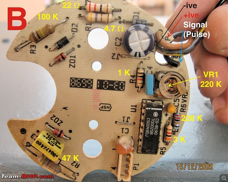
It did the job well but with a difference. Here is the complete picture of the Duel.
My plains are to get three Tachos. One will be used on my M800, second & third will be used to fine tune my carbs of HH S. Splendor, K.Nova 135 (4 Stroke Engine) & NV Spl. (2 Stroke Engine).
I positively feel that I will be able to accomplish this task with the help from Big brothers like you.

At present I have 2 Tachos (A & B) both are from Baja Bikes (’A’ is definitely from a old Bajaj Pulsar and
the other ‘B’, having the Old Bajaj Logo, no idea.)
DIY tacho for a car, using a bike's tacho-ztacho-b.jpg

Now, I have successfully checked ‘B’ with the circuit given by you and also by connecting it to my HH. S. Splendor. But ‘A’ was again stubborn to towards the given circuit & bike as well.
I made one experimental observation, though. I slowly lifted the tip of the armature needle, over the small pin (near 0) and let it go. Naturally the spring action (the snake like coil under the printed dial) tried to bring back the needle to the 0 but the needle stopped in between say number 8. When I powered the tacho, first, the needle came to zero & then when I signaled the pulse wire according to your circuit, It showed movement (1500 RPM). When I removed all the power the needle again went to 8.
Though, after this small experiment I placed the needle again to its original position (i.e. 0)
Now what is your ideas on this. Is there is the something wrong with the Spring Coil ? Its Placement etc.

Quote:
If possible please post a picture of the rear side of the tacho also.
Very much possible. Here is the front & back side of the PCBs
DIY tacho for a car, using a bike's tacho-ztacho-back.jpg
DIY tacho for a car, using a bike's tacho-ztacho-b-back.jpg
DIY tacho for a car, using a bike's tacho-ztacho-b.jpg
Quote:
Hope you have gone through the data sheet
Although, the Data Sheet is complex thing to under for a average like me, I am going through it
again & again and started to get hold of the things a little.
Quote:
post the values of the components Ct & Rt
As you can see in the picture I have 2 Cap(C4, C6) as Ct . I can identify the ceramic (Pale Orange one) but the other is having hard to remove white glue all over it. For Rt, if it is R6 + VR1 I suppose, then it is very much conspicuous. (360 K + 100 K) and I also de-sealed the pot (VR1 was set to 83.5 Ohm before I changed it for trial as you asked for)

With regards
Zmint
zmint is offline  
Old 25th December 2009, 10:08   #27
BHPian
 
ilangop's Avatar
 
Join Date: Jul 2008
Location: Chennai
Posts: 992
Thanked: 903 Times

Hi all,
Seems like I got some problem with the fonts.
So I am attaching a document for your refernce.
-Ilango
Attached Files
File Type: pdf Design of tacho.pdf (12.3 KB, 1343 views)

Last edited by ilangop : 25th December 2009 at 10:20.
ilangop is offline  
Old 25th December 2009, 10:16   #28
BHPian
 
siddvi's Avatar
 
Join Date: Nov 2008
Location: Bangalore
Posts: 54
Thanked: 48 Times

@ilangop: Good job buddy and thanks for all the DIY info.
siddvi is offline  
Old 4th January 2010, 15:03   #29
Newbie
 
Join Date: Dec 2009
Location: Batala
Posts: 16
Thanked: 0 Times

Hello everybody,
Yesterday, I checked Tacho (A) again. Dismantling both tachos, and comparing both of them I concluded that there was something wrong with the armature part. When I checked the resistance of the coils(2 of them), for the faulty tacho, there was no reading in one of them. When I made a very keen observation, Guess What ? It was what we call, ‘I D 10 T problem’ (idiot). I don’t know how but due to some negligence while manufacturing, the thin wire end of one of the coils didn’t had its varnish removed before soldering. It did that part and re-soldiered the joint, and you can well imagine the joy a DIY guy gets after successfully rectifying a fault. But it was that signaling schematic that was helping me all the time. Without it, I still would be looming in dark.
Next, I changed the VR1 from 100 K to 200 K and tuned the tacho to show exactly 3000 rpm.
Now I have two working tackos with me.
They both work great with my HH Super Splendor, but my mighty NV didn’t make them buzz.

I have attached the the wiring diagrams for refference.

What could be wrong ? It is CDI equipped, and I connecting the signal wire to the CDI Out wire (Blue) that goes into the HT Coil. What is your idea ?

Thanks once again for a working tacho to the (end)beginning of the year.
Attached Thumbnails
DIY tacho for a car, using a bike's tacho-zlml-manual-diagram-per.jpg  

DIY tacho for a car, using a bike's tacho-manual-diagram-part-2-per.jpg  

zmint is offline  
Old 11th February 2010, 09:05   #30
BHPian
 
ilangop's Avatar
 
Join Date: Jul 2008
Location: Chennai
Posts: 992
Thanked: 903 Times

Hi Zmint,
Congrats on your success. Could you please post a schmetatic of how the tacho was wired in the HH Splender. Your HH splender is also equipped with a CDI system. So the tacho should have worked the same way as you had done for the splender. Hope the +ve and gnd are connected . Now that you have become an expert I should not have asked this, still only to cross check. :-)
Hope your electronics lab is equipped with a multimeter. Set it to AC 750 V range and measure the voltage at the place where you hooked up the tacho signalling point in both cases. As well check if both tachos still work after you experimented on the NV.
-Ilango
ilangop is offline  
Reply

Most Viewed


Copyright ©2000 - 2024, Team-BHP.com
Proudly powered by E2E Networks