| |||||||

| Search Forums |
| Advanced Search |
| Go to Page... |
 |
| Search this Thread |  15,940 views |
 11th June 2022, 00:05
| #1 |
| BHPian Join Date: Mar 2021 Location: Mumbai
Posts: 239
Thanked: 1,809 Times
| DIY : Solar Power Conditioning Unit Prelude : The search began back in 2019, we wanted to install a small solar power generation unit on our rooftop(terrace) and consulted with multiple companies and even visited MSEB to inquire about the same. Most of them suggested us to opt for on-grid systems ranging between 2kW to 5kW. Sharing some quotes :
Fast forward to 2022, we were hit with the deadly combo of hottest summers and power cuts, power cuts in my area are super rare so we've never really thought about getting an inverter but this year was a bit different, even 10 minutes without a fan during afternoons felt like a major inconvenience. We again started exploring options about solar power on a very small scale and tried to get quotes for smaller off-grid setups, meanwhile I started an extensive research about the feasibility of small scale solar setups. Our Requirements : I had started the switch to power efficient appliances long ago, the old appliances which reached their end of life were replaced with their power efficient counterparts, this includes the switch from CFL to LEDs, from induction motor fans to BLDC fans and so on. The requirements were minimal, all that we wanted was a 3-4hr backup with 2 x 28 watt BLDC fans, 2 x 5 watt LEDs and laptop/phone charging. Why Off-Grid? A 3kWh unit in place would've generated 10-15 units of power per day which in normal conditions would mean around 300-400 units per month and leaving the 2-3 summer months I would be selling the surplus to Mahadiscom at a rate of around ₹2.90 per unit and they've also proposed grid support charges to be levied on consumers. Also the grid tie inverters come with a feature called anti-islanding which disconnects solar power from the grid during power cuts for safety reasons which means you need a separate backup when the grid is down. Hybrid options were available but they were very expensive, so decided to go with an off-grid setup. Why DIY? I had ordered a Luminous solar charge controller which I got at a discounted rate of ₹450 from amazon, thought of using it to charge my phone initially. Coupled it with an old solar panel and a 7Ah UPS battery, this made me more curious about whether we really needed an inverter. After some digging around with square wave vs modified sine wave vs pure sine wave inverters I went ahead and ordered a Luminous Eco Volt Neo 850 sine wave inverter. The unit I received had two minor dents so I had thought about getting it replaced, but I decided to run some tests before returning it to check the actual efficiency and here are the results : Idle power consumption : 0.85A (10.2 Watts) Light Load (20W) : 3.34A (40.08 Watts) ~49.9% Medium Load (100W) : 10.22A (122.64 Watts) ~81.54% Found out that these inverters have an efficiency curve depending on the load percentage which is not public, they just list the peak efficiency. Returned the product and stumbled upon Microtek Solar PCU, it was fairly affordable and the concept of switching to solar when the panels were producing surplus power was exactly what I was looking for but the efficiency was not listed on their site. It was listed as <80% on some sites and 0.88% on others, called them up to confirm the same and they confirmed that it was <80% and after telling them my requirements the suggestion from their side was : Panels : 4 x 330Wp - ₹49,200 PCU : 1 x 935VA - ₹8,500 Battery : 2 x 150Ah C10 - ₹30,400 I had mentioned that I need to run just 2 BLDC fans and 2 LEDs. This was a very overkill setup and when I asked the sales guy about the same he mentioned that this was a bare minimum setup. I made up my mind that I won't be going anywhere near 1kWh or even 0.5kWh for a power requirement of 0.07kWh. Again contacted several agencies and when I mentioned that I need a setup smaller than 0.5kWh there was an evident loss of interest from their side which is understandable considering less parts = less commission. So thought of doing it by myself, keeping the solar PCU as a template. Deciding The Voltage & Panel Capacity : Decided to go with a 12V system as it was a good base and I had the option to convert it to a 24V one by adding another battery and connecting them in series. As for the panels I decided to go ahead with 2 x 165wp and keeping the setup as small as possible. Went to local vendors for the panels and even they were not interested in selling 165w panels and some of them mentioned that 330w panels won't even be able to charge your battery properly and suggested to buy 2 x 330wp. Decided to buy panels online as well, ordered a Microtek panel from flipkart for ₹5,800 and a Luminous panel from amazon for ₹6,300 both 165wp. Ordered a 12V 40Ah C10 battery from zunsolar for ₹4,000 (more on this later). Deciding The Inverter : DC to AC to DC conversion is very inefficient and for this reason I wanted to skip the inverter and keep everything in DC. There was this generic DC to AC converter popping up during my search : 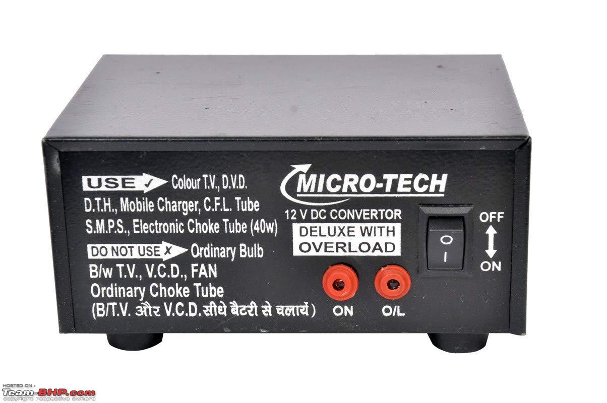 After watching some videos on youtube about working of this converter found out that it is not a DC to AC converter but a 12V DC to 300V DC converter, seemingly built with poor quality components. Then I came across this video : This video shows that it was possible to run Atomberg Efficio (my fan) directly on 24V DC. While I was able to replicate it on one fan the other fan in my room was a newer version which did not work with direct DC. So had to continue the search for inverters, there was a lot of debate between pure sine wave, modified sine wave and square wave inverters with most of the online discussions and articles suggesting to opt for pure sine wave inverters. Went back to basics, looked at how modern SMPS work and went ahead with a Portronics CarPower One (150W) modified sine wave inverter. Wanted to check it's efficiency : Idle power consumption : 0.2A (2.4 Watts) Fan Speed 5 (28W) : 2.9A (34.8 Watts) ~80.46% Fan Speed 4 (19W) : 1.83A (21.96 Watts) ~86.52% Fan Speed 3 (14W) : 1.26A (15.2 Watts) ~92.1% With both the fans running at full speed the power consumption was 5.83A (69.96 Watts) the small inverter returned an efficiency of ~80.05% which was decent enough. It gets slightly warm after 2-3hrs of operation but that's fine considering the size, the internal cooling fan is small and has to operate at higher rpms to push a reasonable amount of air, I plan to shift it to a bigger acrylic box with a quiet arctic fan for good airflow after a few weeks. Deciding The Battery : Every solar system needs something to regulate the voltage and current as the power from panels is not stable throughout the day, initially I wanted to go the super-capacitor route but soon realized that the total cost was nearing around ₹4,000 for the super-capacitor setup so instead went with a zunsolar 40Ah C10 battery. Super-capacitor setup working with the battery will remain in my to-do list for this project, here's a proof of concept video that I came across : I went with a traditional battery setup as apart from acting as a voltage regulator during the day it also had the ability to provide backup at night. Here's the estimated backup with one fan (speed-4) : 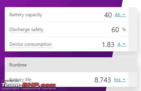 Estimated battery backup with two fans (speed-4) and 2 leds : 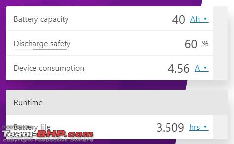 Deciding The Charge Controller : I had ordered a Luminous charge controller(Model : 1220NM) before getting started with this project, but decided to stick with it as it was sufficient for current application. There are basically two types of charge controllers : PWM and MPPT. MPPT charge controllers available on the market are more efficient but come at a cost and don't work as well with small setups while PWM charge controllers are fairly cheap but inefficient. Won't be getting into detailed comparison as there are many good articles/videos readily available for the same. Last edited by Venky03 : 16th June 2022 at 11:23. |

|  (31)
Thanks (31)
Thanks
|
| The following 31 BHPians Thank Venky03 for this useful post: | aargee, AdityaDeane, aps88, AVIS, BoneCollector, Chhanda Das, Fuldagap, graaja, GTO, Herschey, InControl, Javelin, Jeroen, Joelinf, KK_HakunaMatata, Leoshashi, maddyg, Nrulz, parsh, PM - B, Prakritij, pugram, pun337, Ravi Parwan, SanSabh, sridhar-v, subie_socal, t3rm1n80r, vaasu, Vishal.R, vzvish91 |
|
20th June 2022, 16:54
| #2 |
| BHPian Join Date: Mar 2021 Location: Mumbai
Posts: 239
Thanked: 1,809 Times
| Parts Used 165W 12V Solar Panels   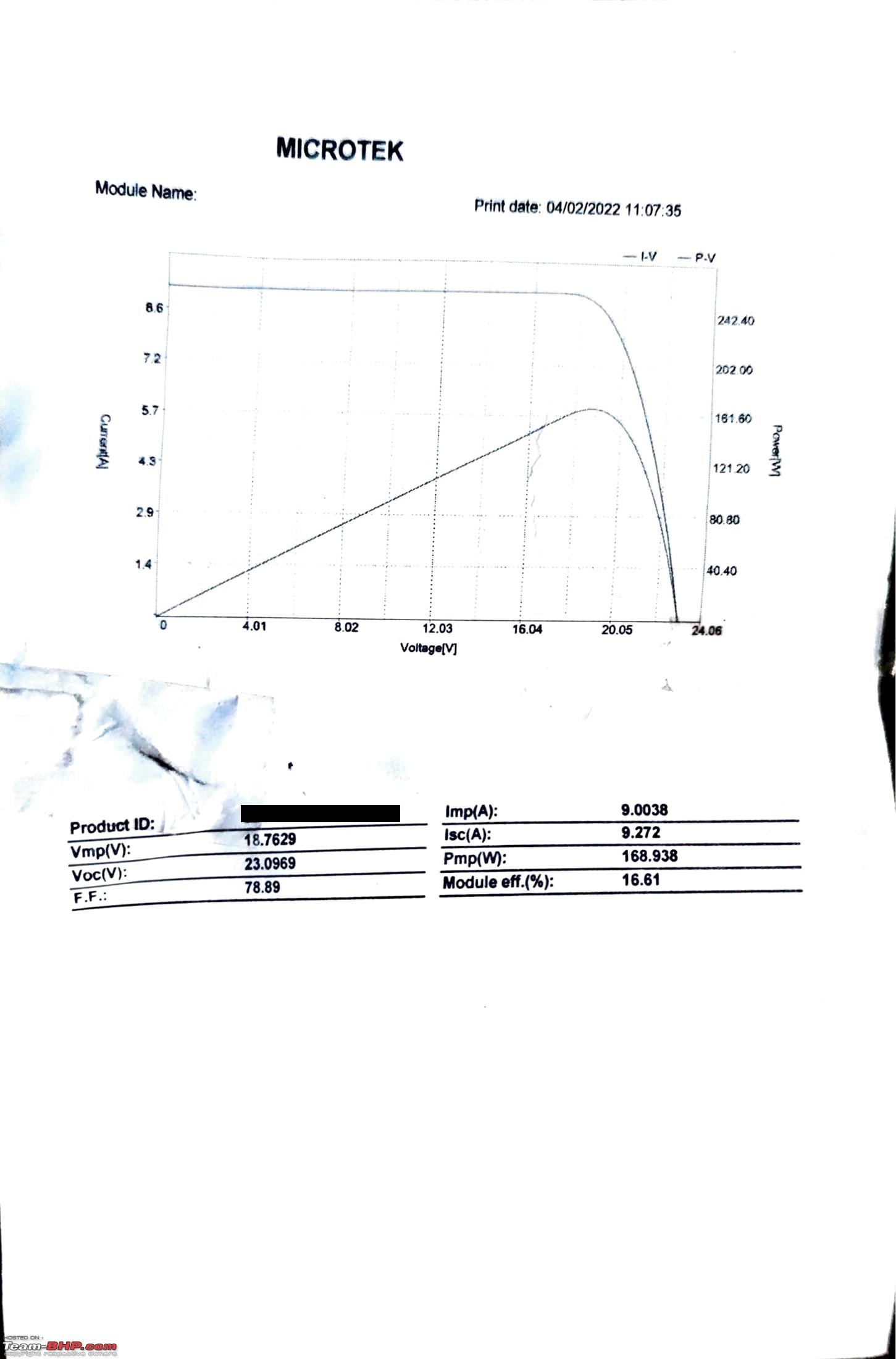  I purchased one Microtek panel and one Luminous panel, went with poly-crystalline as there was no substantial benefit in going with mono-crystalline panels for small setups. Both have identical dimensions with the Luminous one providing slightly better power output.(better on paper as well) Luminous 1220NM Solar Charge Controller  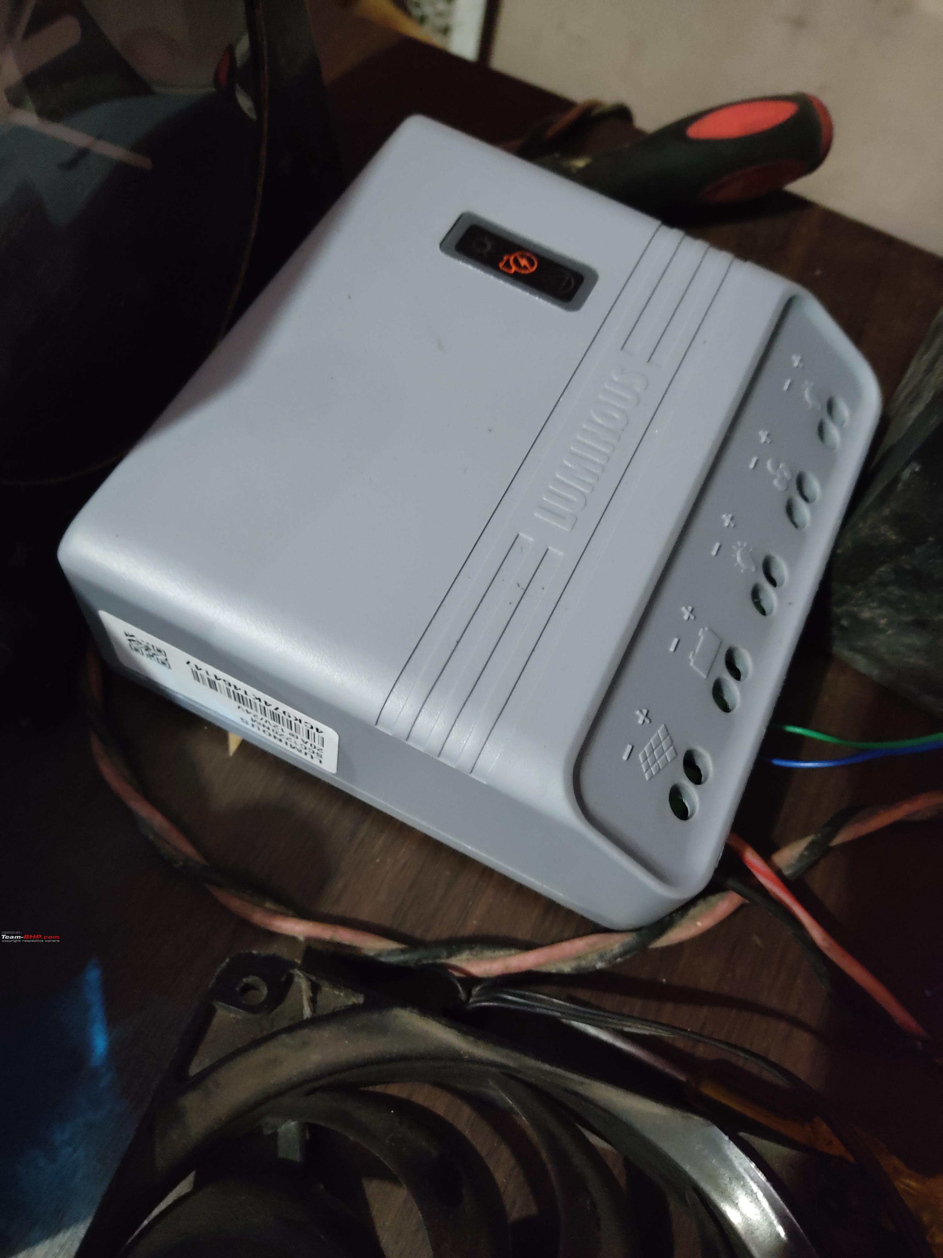 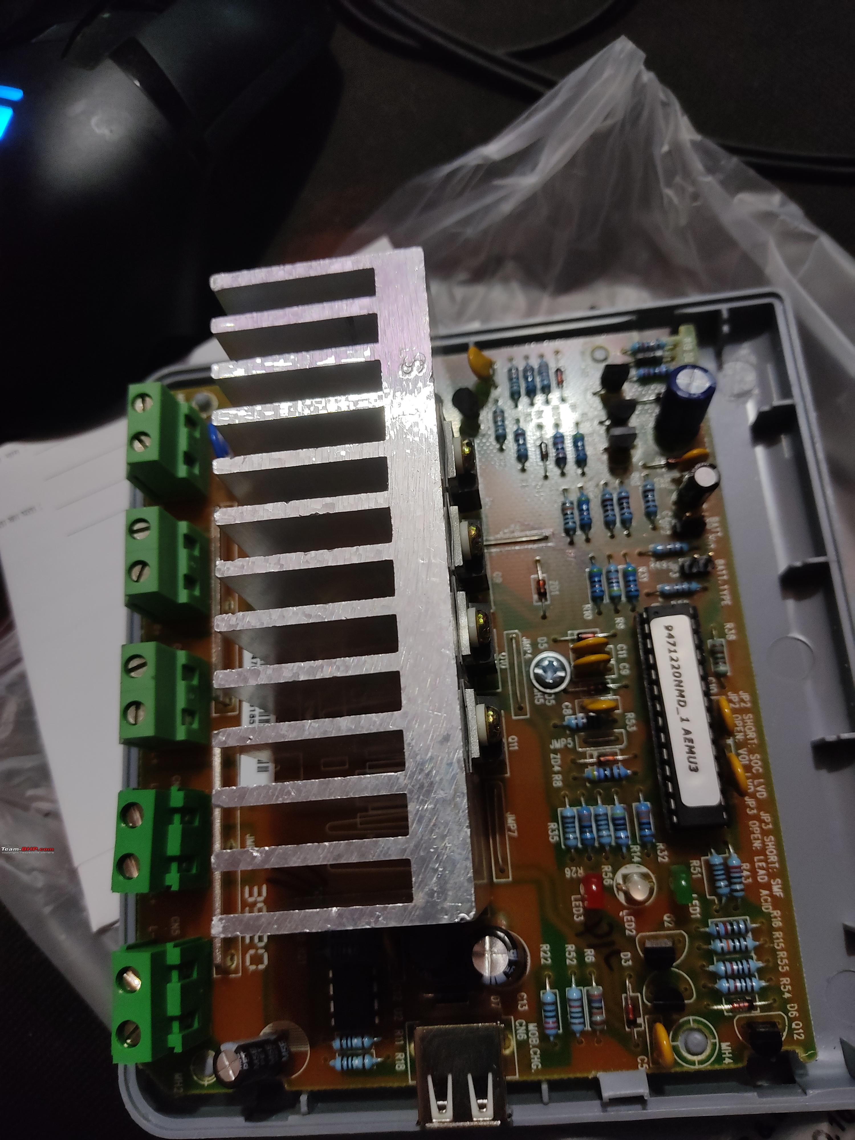 Main function is to charge the battery, lacks battery temperature sensor but compact and easy installation. Also huge heatsink to passively cool the mosfets, other chinese charge controllers available on the market do not have adequate cooling and won't last long. The USB voltage is on a higher side at 5.55V and that's the reason I won't be using it to charge/power any 5V gadget. Zunsolar Power Plus 40AH C10 Battery  It was reasonably priced and was the perfect capacity for my requirement. Don't know much about the brand but time will tell. Portronics CarPower One 150W Inverter  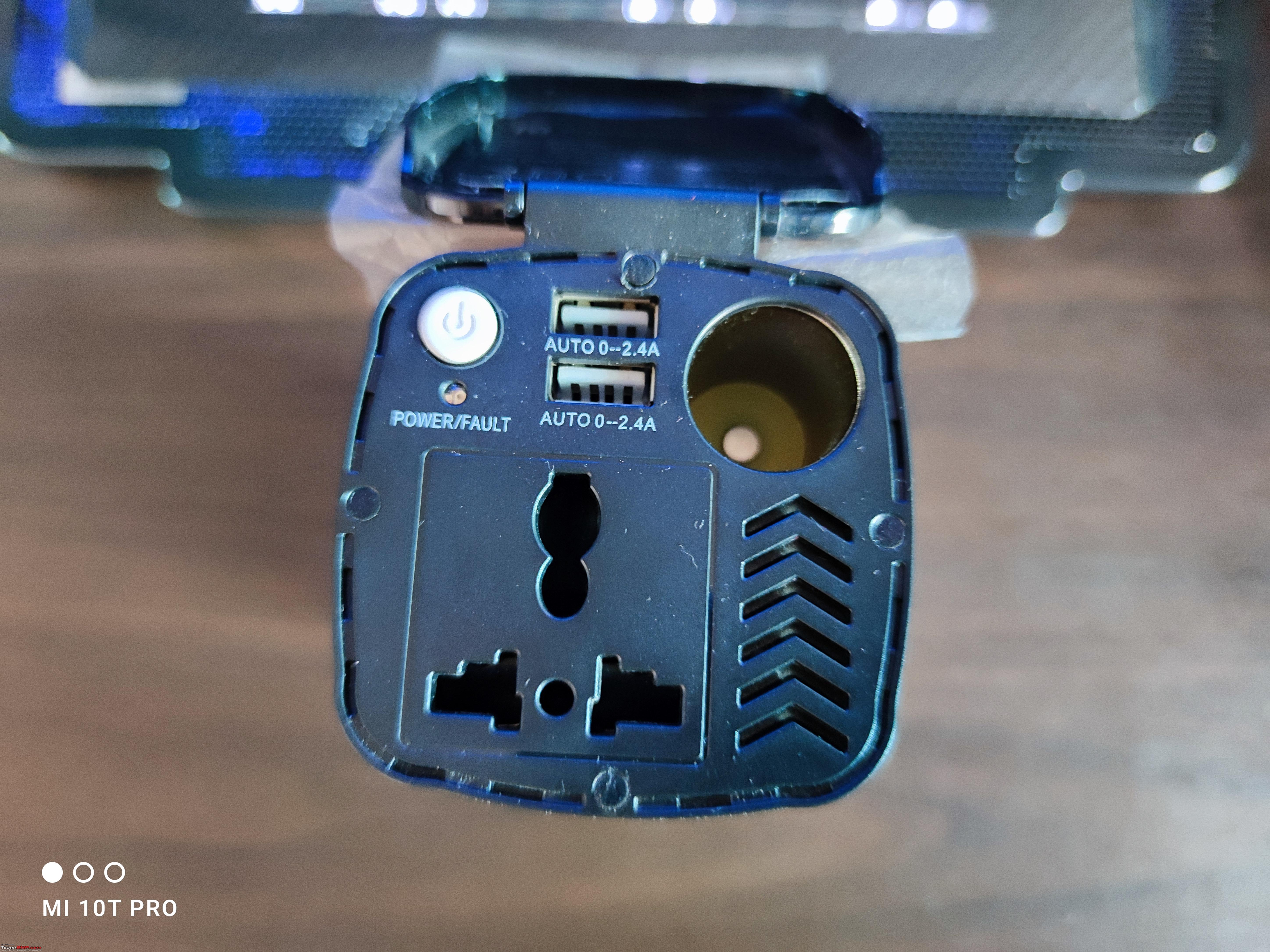 Very compact when compared to traditional inverters, no coil whine, low idle power consumption and decent efficiency. Usable 5V rail at 4.98V, will put detailed summary in the next post. Other options were either too expensive or did not have proper reviews. Wiring & Connectors 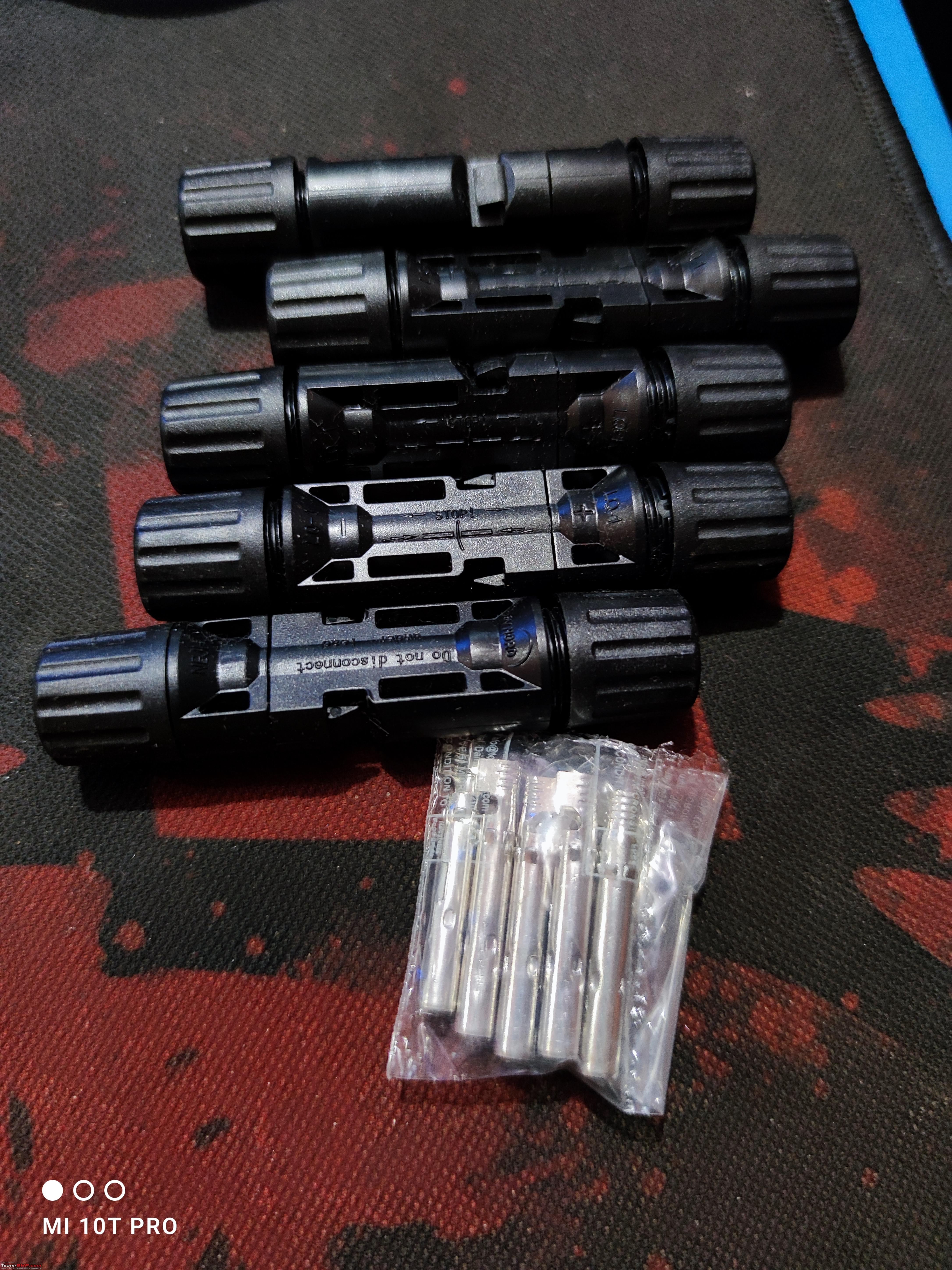 Ordered the MC4 connectors from amazon, still have some left. Using Microtek 4 sqmm DC cable for the main 12V rail (panels to controller, battery to controller), 14 awg cable to connect inverter to the 12V rail and 0.75 mm cables for everything else. Have checked the ampacity and this configuration should work fine for 12V as well as 24V setup if I plan to do so in future. MCB & Breaker Box 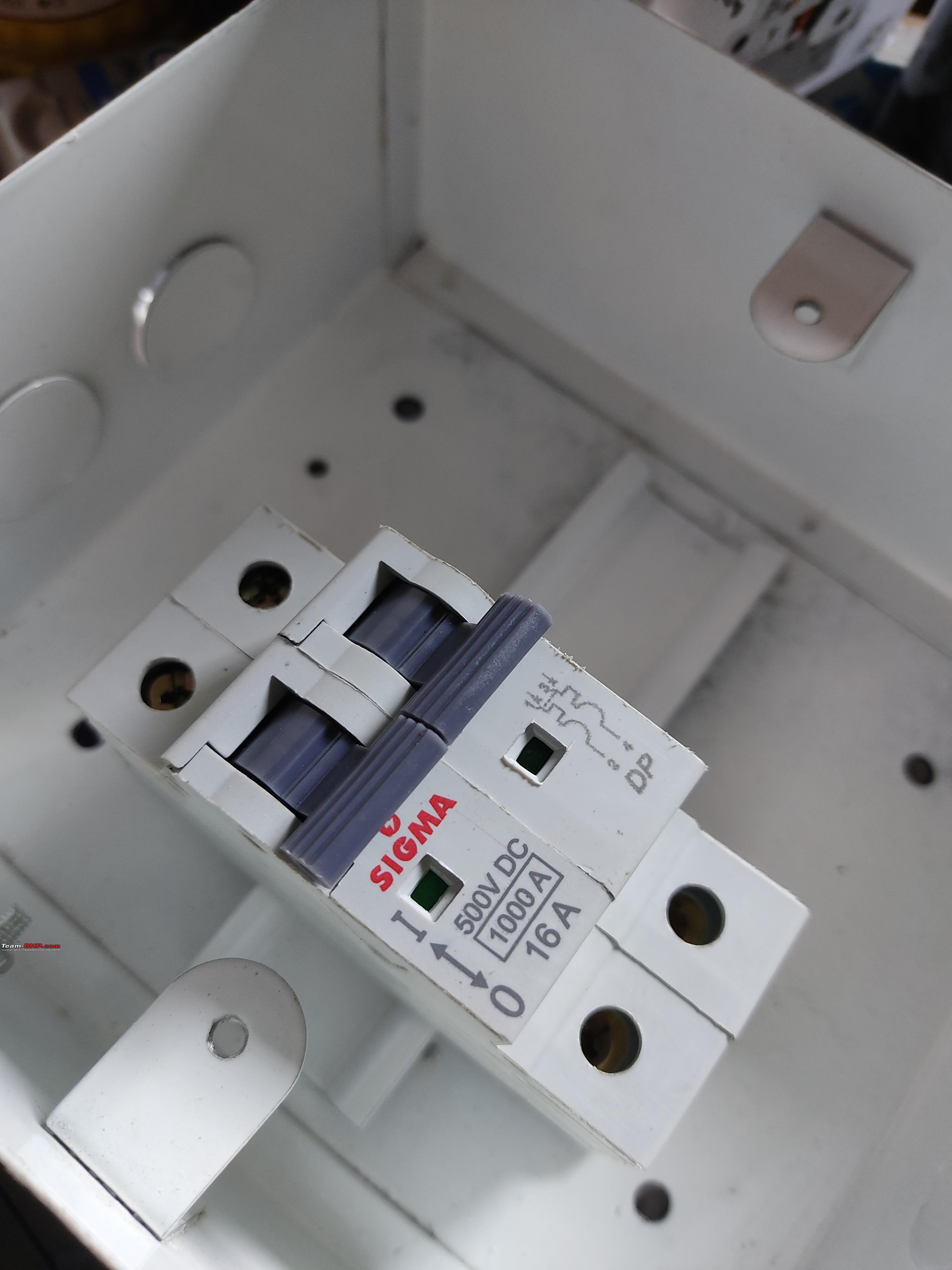 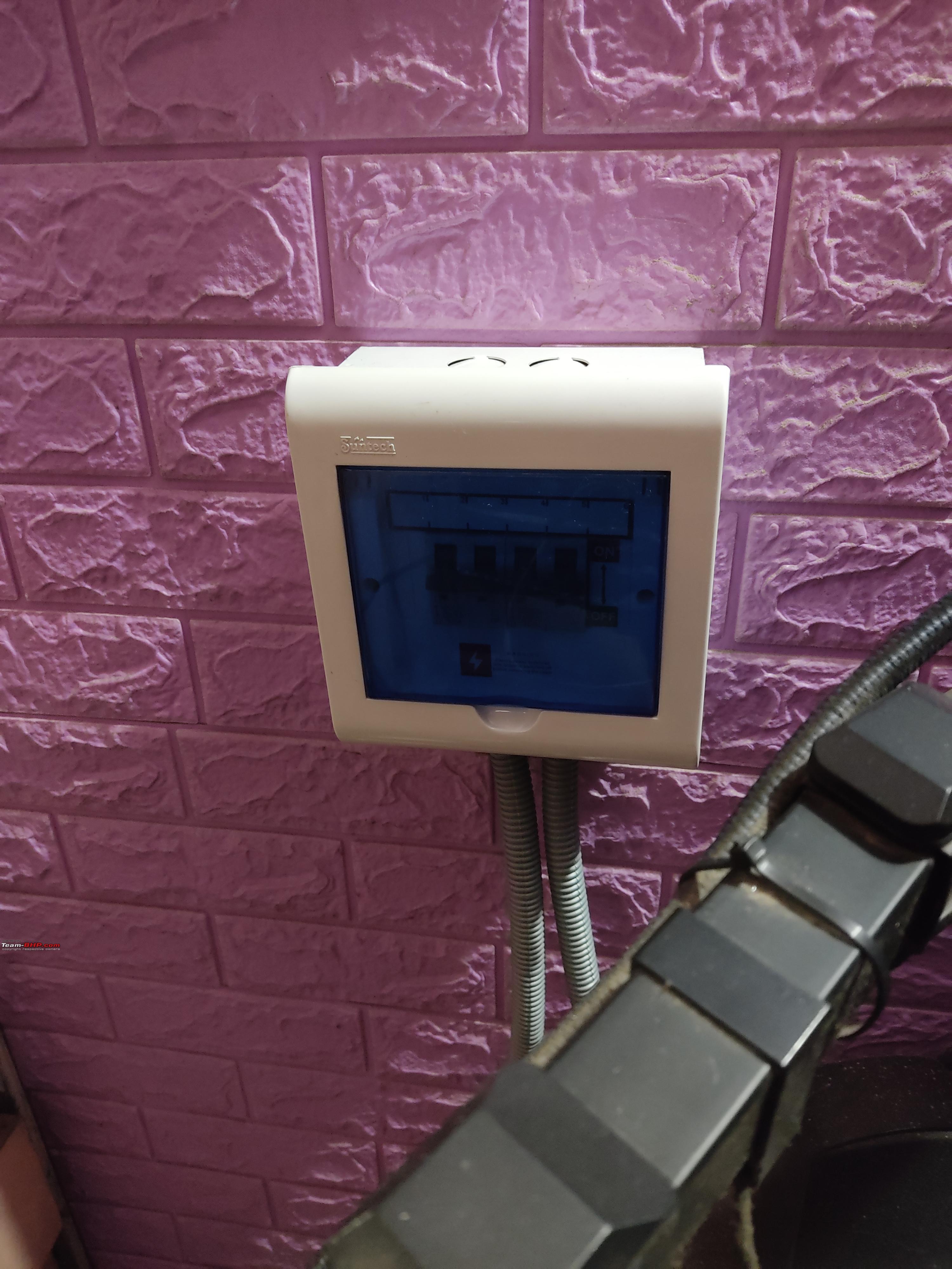 Using 16A DC MCB for the battery connection and 25A DC MCB for the panels. Used spare AC breakers for the mains and inverter output. Ordered two Suntech breaker boxes, one for DC and one for AC. The one in the picture is the DC breaker box. Microcontroller Board & Sensors   Using an arduino uno clone for the PCU and a wemos D1 board(optional) to upload voltage and current readings on Blynk. Purchased the following sensors :
Relay & DC-DC Converters 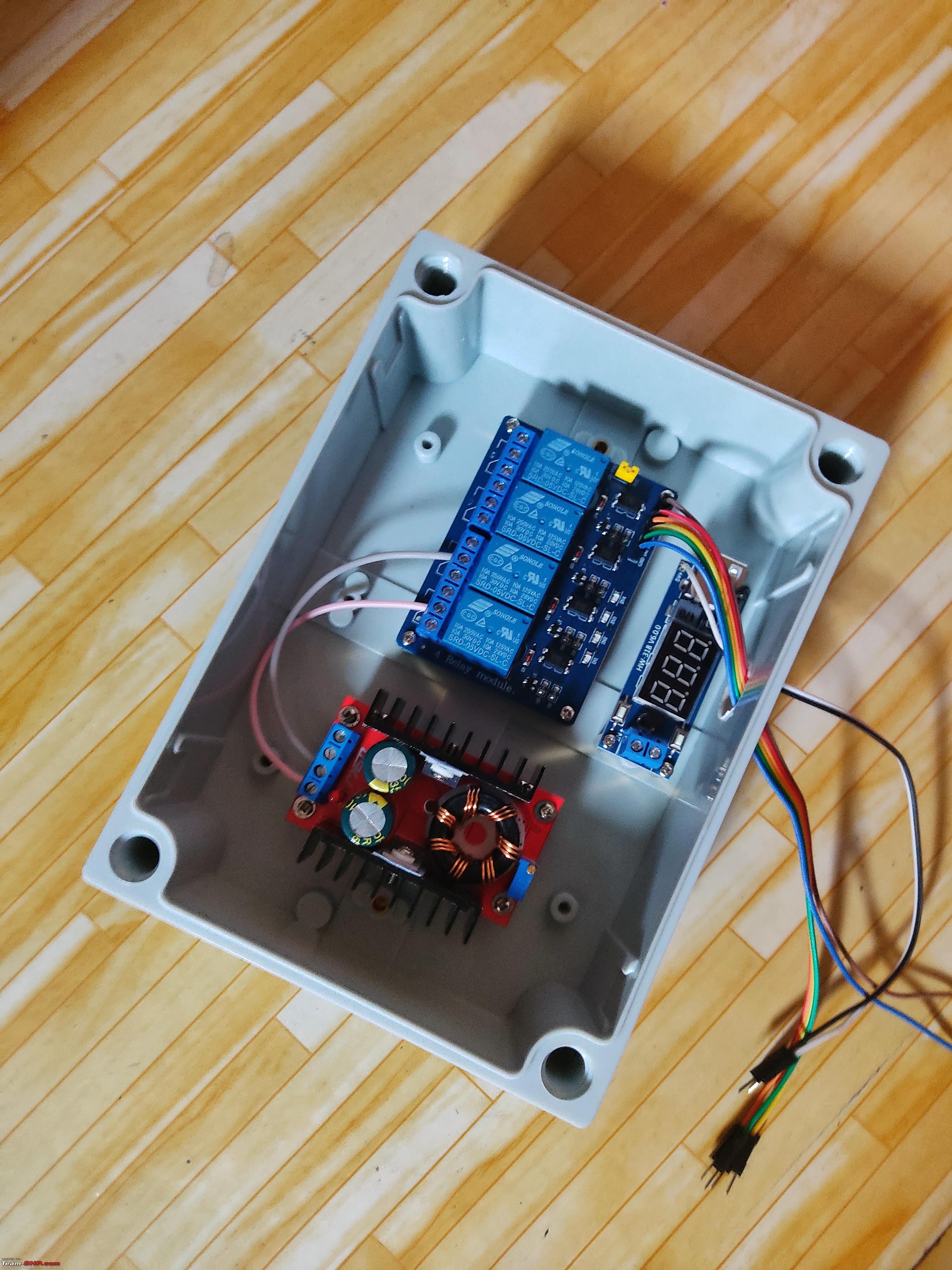 Using a 4 channel 5V relay for the main switching, 2 x 5V buck converters(one for relay and one to power arduino) and a 150W boost converter. Decided to maintain a separate 5V supply for the relays as I'll be adding more of them later on. Miscellaneous 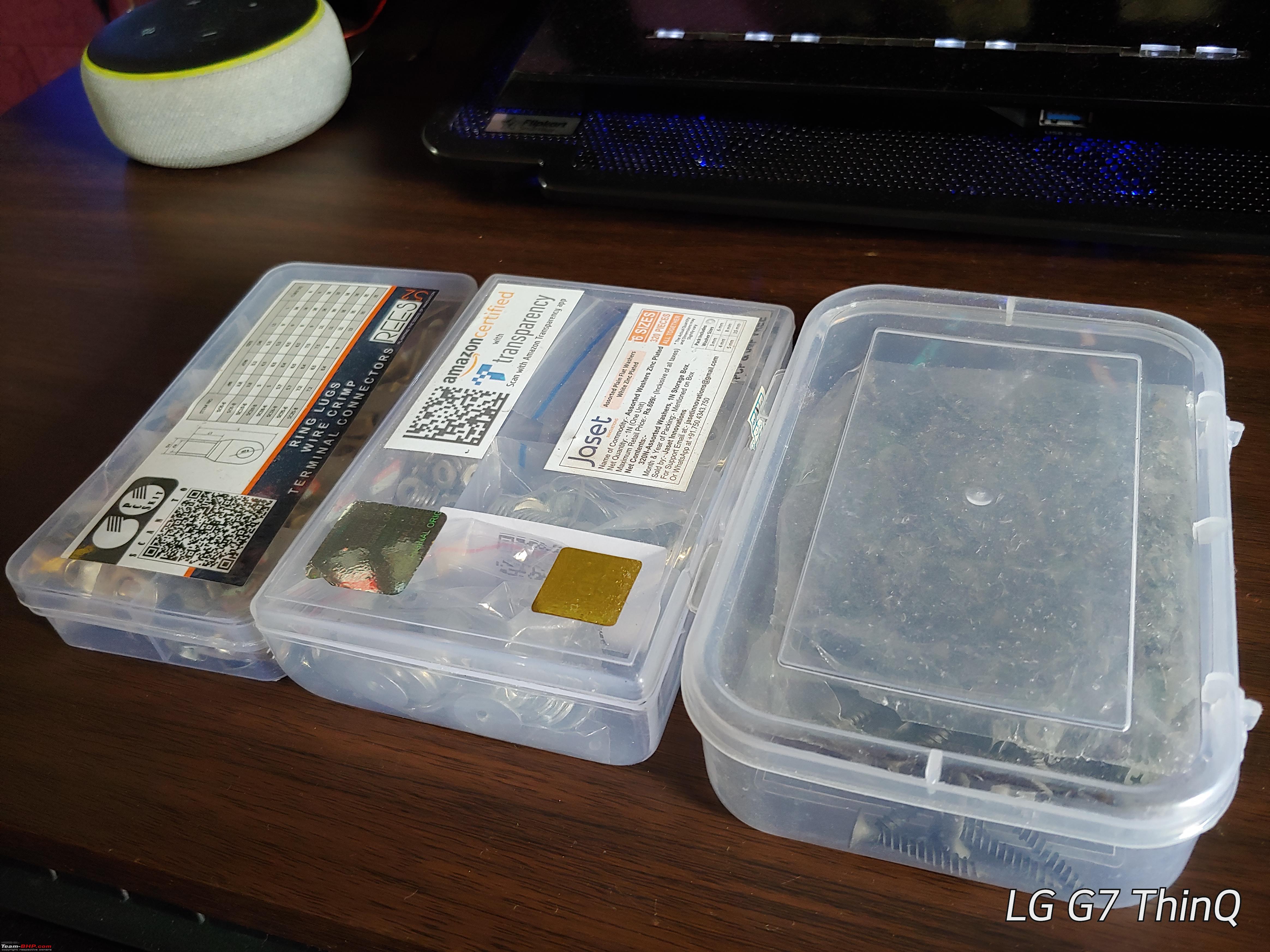
Last edited by Venky03 : 21st June 2022 at 11:34. |
|
| (21)
Thanks
|
| The following 21 BHPians Thank Venky03 for this useful post: | aargee, AdityaDeane, aps88, ashpalio, BoneCollector, Chhanda Das, condor, Fuldagap, gischethans, graaja, GTO, Herschey, InControl, Jeroen, parsh, Prakritij, pugram, SlowRider, SYSTEMIZED, unknownartist01, vzvish91 |
|
21st June 2022, 14:45
| #3 |
| BHPian Join Date: Mar 2021 Location: Mumbai
Posts: 239
Thanked: 1,809 Times
| Portronics CarPower One 150W Inverter Making a separate post for this as I spent a lot of time researching about the difference between working of square wave, modified sine wave and pure sine wave inverters. Saw a lot of blogs and videos which mentioned that square wave and modified sine wave inverters will cause :
Putting up waveforms for interested users. Grid AC Waveform(Pure Sine Wave)  Portronics Inverter Waveform(Modified Sine Wave)  Harmonics are a cause of concern for sensitive loads but not for simple appliances. To verify the claims about overheating :
Used an infrared thermometer to take the temperature readings, the ambient temperature was 30.6°C and here are the results :  Did not find any noticeable difference in the surface temps and there was no buzzing sound. Coming back to Portronics CarPower One, here are the internals :   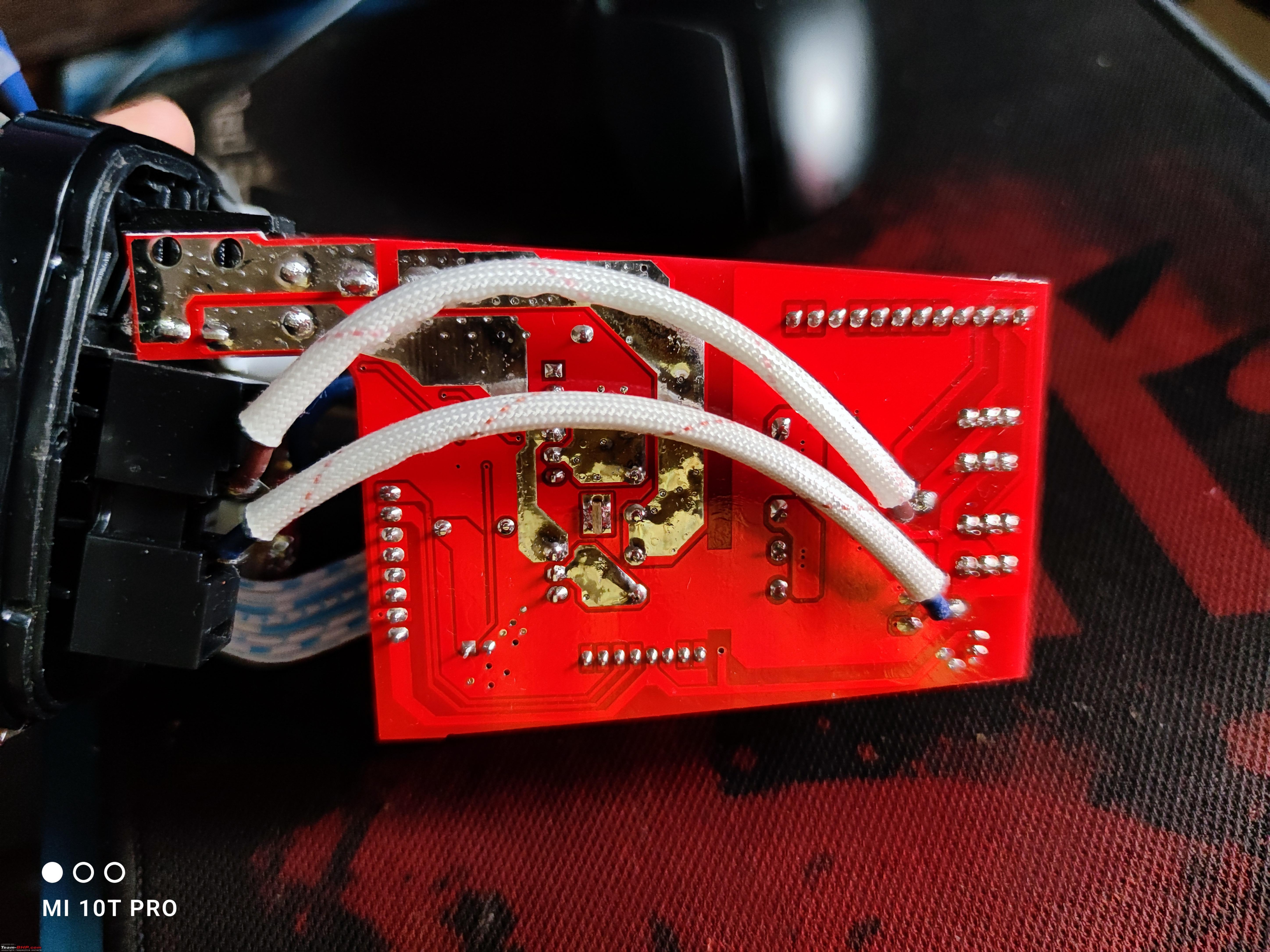 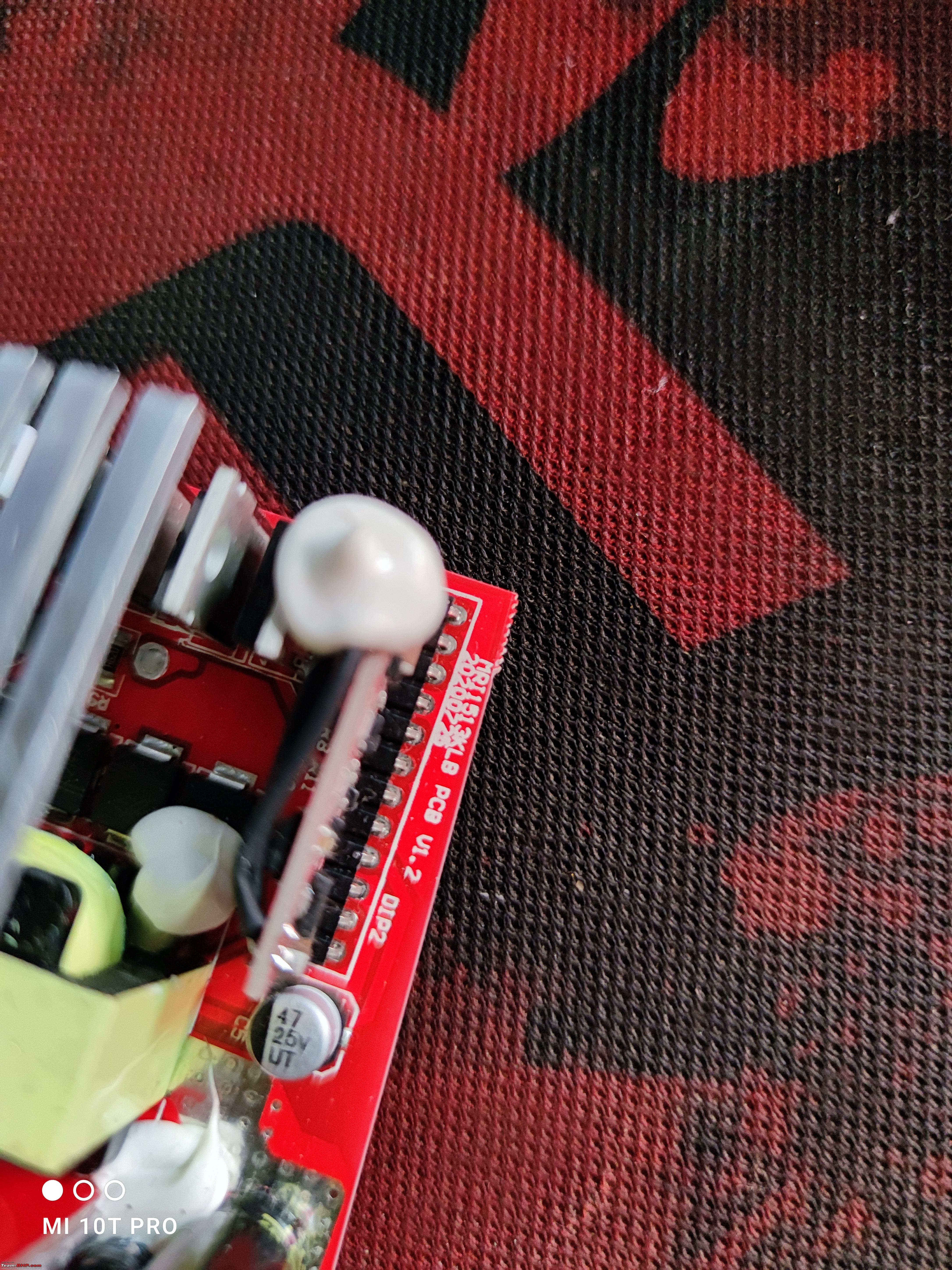 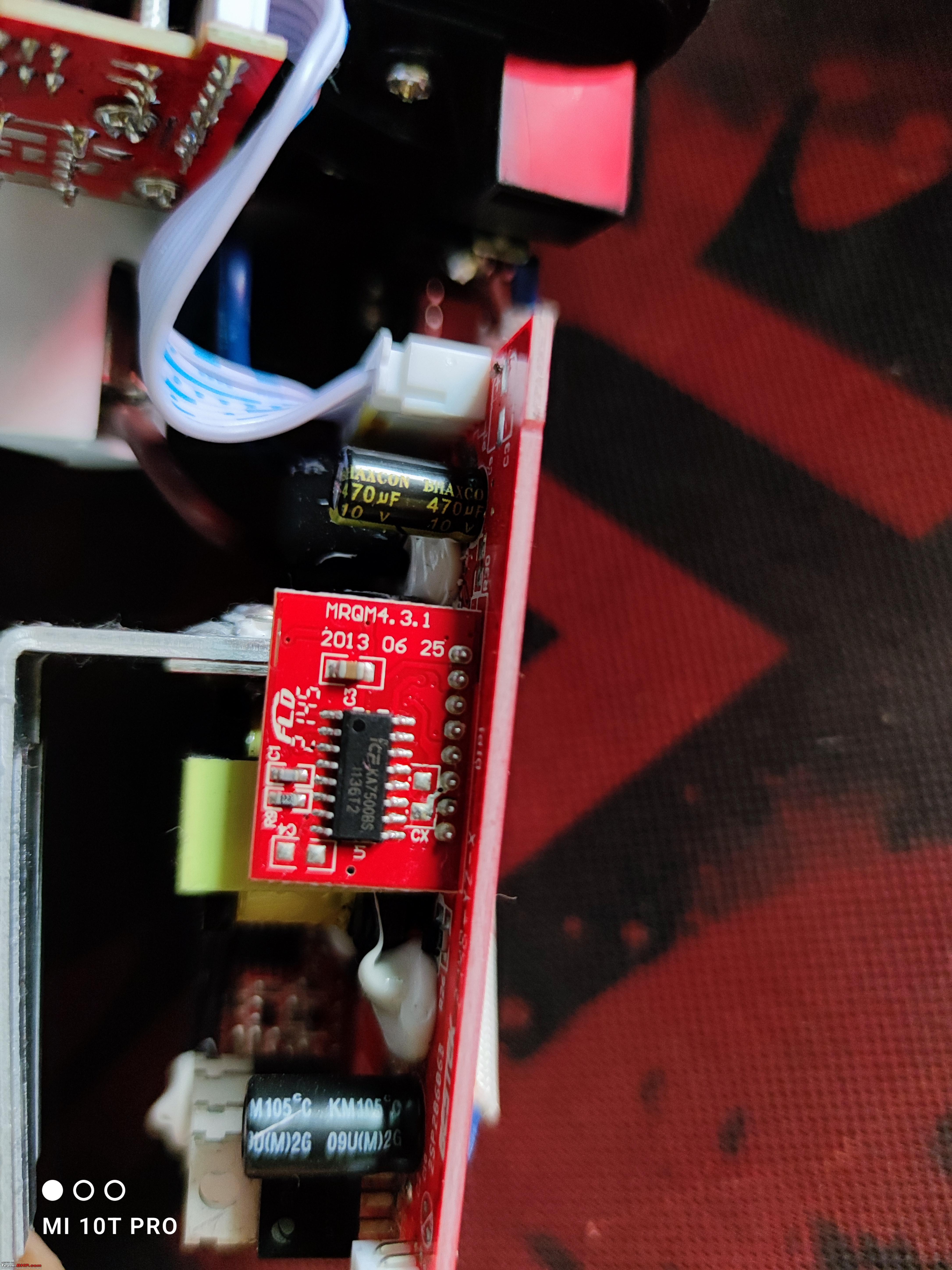   It is a rebranded Bestek 150W Car Inverter, based on KA7500B driver board and uses a ferrite core transformer.(correct me if I'm wrong) The 5V rail is usable at 4.98V and I'm using it to power the wemos D1. If you're looking to buy an inverter to charge your laptop on the go I would recommend going with the mid-size or bigger units and avoid the ones which look like these : 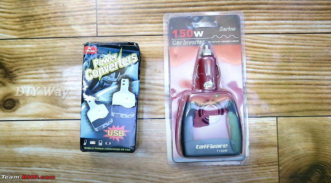 Image Credits : DIY Way Youtube The first reason is that the components are crammed in and are not adequately cooled, second reason is that the traces on pcb are not enough for the amount of current and the third reason is that if it is super compact then it is most likely supplying 230V DC. They can work perfectly fine for light loads but the traces will burn out if you put any load greater than 80-100W. Last edited by Venky03 : 23rd June 2022 at 08:00. |
|
| (16)
Thanks
|
| The following 16 BHPians Thank Venky03 for this useful post: | aargee, AdityaDeane, adityadeva, AROO7, BoneCollector, Fuldagap, gischethans, GTO, InControl, Jeroen, kiranknair, Nrulz, parsh, Prakritij, Ravi Parwan, vzvish91 |
|
23rd June 2022, 10:15
| #4 |
| BHPian Join Date: Mar 2021 Location: Mumbai
Posts: 239
Thanked: 1,809 Times
| Solar Power Conditioning Unit Solar power conditioning units are very similar to hybrid solar backup inverters but instead of just providing backup when the grid is down they also have the ability to completely disconnect the grid and switch to solar when the panels are producing enough power. While searching for Solar PCUs with smaller capacities I found one from Smarten and one from Microtek. Was unable to find any datasheet for the Smarten one and the one from Microtek was on a expensive side considering the fact that it had a PWM charge controller, also none of them supported batteries less than 100Ah so decided to go the DIY route. Prototyping  The first step was to determine the accuracy of the sensors and calibrate them. The accuracy of your sensors will greatly depend on the stability of 5V supply, also have to make sure that you calibrate the device according to the 5V rail of the power supply and not your laptop, for example if you calibrate the sensors on a laptop with 5V rail at 5.15V then the readings will be inaccurate on a power supply 5V rail at 4.98V. The 25V voltage sensor was fairly accurate with the sensor showing 12.92V and the multimeter showing 13.03V. The ACS712 current sensor was showing mixed readings, fluctuating between 3.2A to 4.0A for a 3.98A load while the WCS1800 current sensor was very accurate at 3.92A. Decided to discard the ACS712 current sensor for two reasons : inaccurate readings and the screw in terminals were not big enough for 4sqmm wires. Did not spend a lot of time calibrating the ZMPT101B AC voltage sensor as it's only function in this setup was to determine whether the grid is connected or disconnected. I've programmed it to switch to solar when the battery is fully charged and continue to run on inverter till the battery level is greater than 90%, when it drops below 90% it'll allow the battery to charge back and continue the cycle. In case of power loss it'll run on the inverter till the battery level is greater than 60%. I'm using a 4 channel 5V optocoupler relay to switch between grid and inverter.   This box also contains a 5V DC-DC converter which powers the relays and the ZMPT101B AC voltage sensor. Inverter is isolated from grid and there's a delay of 2 seconds while switching over to avoid any issues, some say that it is fine to connect inverter neutral to grid and theoretically it should be fine but I'm keeping everything isolated. There are MCBs in place from mains to relays and from relays to load. The second box is for arduino, display, sensors and buzzer, also the arduino is mounted in a way that allows me to program it without removing the cover every time. Everything in both the boxes is properly mounted with M2.5 screws, the connections will be soldered once I add in a separate set of DC rails and relays. Here's how the entire setup looks like :  Yes, wire management is definitely on the to-do list. This could've been even more compact with proper space management or a 3d printed case but for now this'll suffice. Also you must've noticed that the panel is placed in my balcony(east facing) at an angle of almost 80° which receives direct sunlight only till 11am(most of which is blocked by a coconut tree) which are not proper conditions to place a panel, but even in these conditions the pcu can power one ceiling fan for around 5-7hrs off-grid on a sunny day. The panels will be placed on our terrace rooftop : 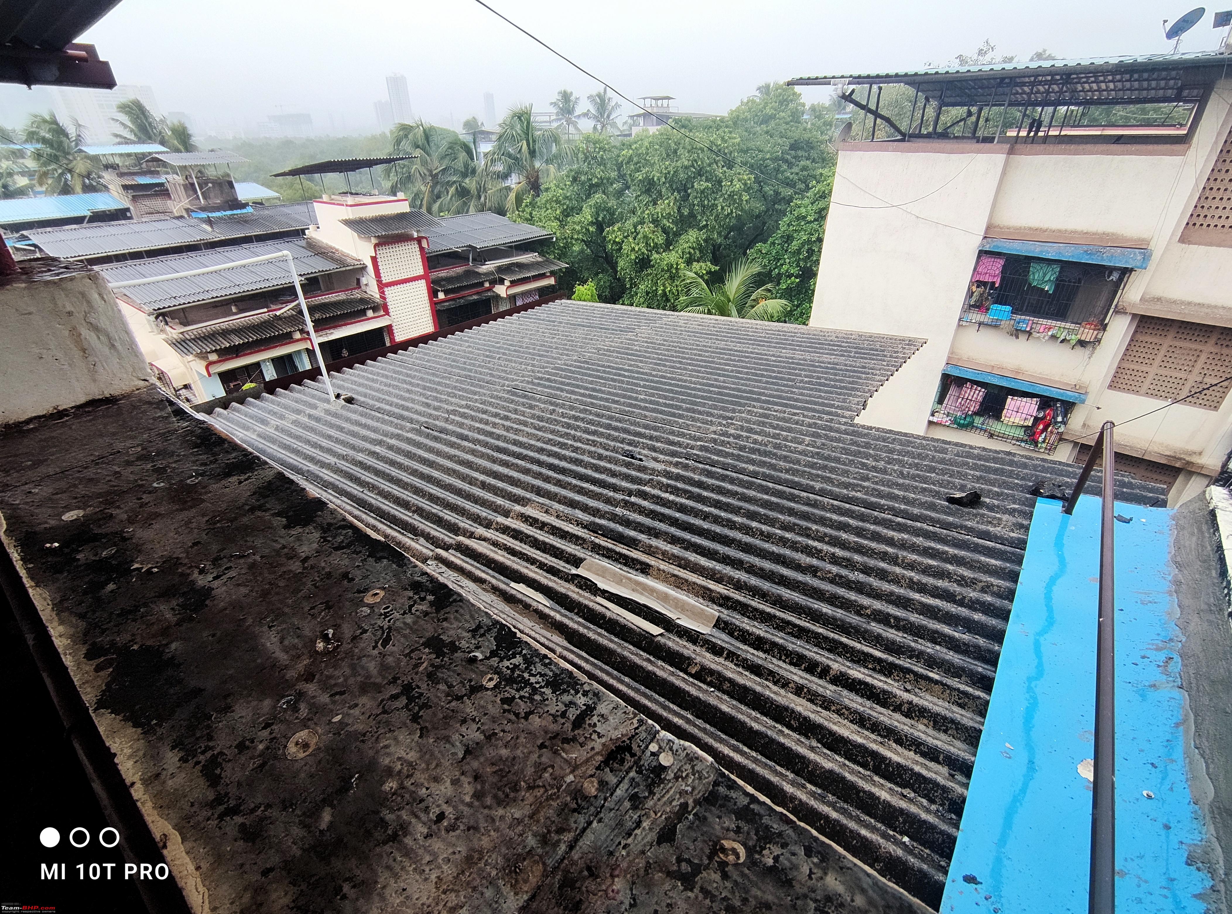 The wemos board is hidden behind the battery, for now it uploads the panel current, voltage and power readings to the cloud, plan to add a battery temperature sensor later on. Here's how it looks like on the Blynk app (single panel) : 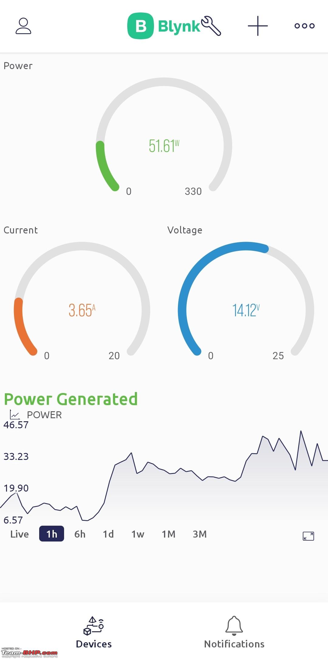 Power output on a cloudy day :  PWM in action : 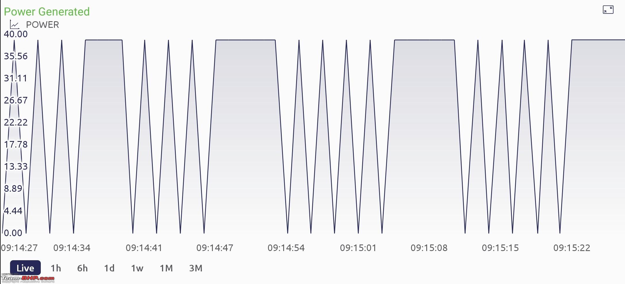 Will post the updated power output graphs once the panels are placed on the rooftop. Last edited by Venky03 : 23rd June 2022 at 14:47. |
|
| (17)
Thanks
|
| The following 17 BHPians Thank Venky03 for this useful post: | aargee, AdityaDeane, ashpalio, BoneCollector, Fuldagap, gischethans, graaja, GTO, hortons15, Jeroen, Nrulz, parsh, Prakritij, pugram, SlowRider, TrueDreamer, vzvish91 |
|
23rd June 2022, 16:46
| #5 |
| BHPian Join Date: Mar 2021 Location: Mumbai
Posts: 239
Thanked: 1,809 Times
| Total Cost & Links I purchased the Microtek panel from flipkart and Luminous panel from amazon and both of the listings are out of stock - ₹5800 x 2 Luminous 1220NM Solar Charge Controller - ₹689 Zunsolar Power Plus 40AH C10 Battery - ₹4199 Portronics CarPower One 150W Inverter - ₹2599 Kenbrook MC4 Connectors - ₹475 Microtek 4sqmm DC Cable - ₹1199 Kenbrook DC Breaker - ₹549 x 2 (1x16A, 1x25A) Suntech Breaker Box - ₹298 x 2 Uno R3 CH340G ATmega328P - ₹799 25V Voltage Detection Module - ₹79 ZMPT101B AC Voltage sensor - ₹219 WCS1800 Current sensor - ₹849 4 Channel 5V Optocoupler Relay module - ₹169 DC-DC 4.5-40V To 5V Step Down Converter - ₹249 Wemos D1 ESP8266 - ₹425 (Optional) XL4015 5A DC-DC Step Down Adjustable Buck Converter - ₹125 (Optional) 1602 Parallel LCD Display with IIC/I2C interface - ₹299 (Optional) Piezo Electronic Buzzer - ₹31 (Optional) M2.5 Standoff Cylinders + Screws + Nuts - ₹649 (Optional) 12V Cigarette Lighter Socket - ₹299 (Optional) ABS Junction box with transparent cover - ₹610 x 2 (Optional) Spring mechanism two pole wire connectors - ₹49 (Optional) Total (Without optional) : ₹24,819 Total (With optional) : ₹27,916 Total (PCU Components only) : ₹5,652 All of these components will be available much cheaper locally but dropping online links for convenience as I ordered most of the parts online. If you're thinking about going the solar route I would recommend switching to efficient appliances first and then calculating your capacity requirements. Be very careful when dealing with agencies, they'll convince you to buy more than you need(like every other industry) for example I was told that I would be saving ₹7000 monthly with a 5kW setup, here's how they've calculated it : 5kW = 600 units monthly x ₹11.82 (MSEB 500-1000 units bracket) = ₹7092 and here are my actual savings : 5kW = 220 units (my average monthly consumption) x ₹7.34 (MSEB 100-300 units bracket) + 380 units (surplus power) x ₹2.9 (MSEB buy back rate) = ₹2716 which will also affect the ROI time(for an investment of ₹2,94,465), instead of 3.4 years you will be looking at ROI time of 9 years. Additional Links : Battery Life Calculator Wire Size Calculator Battery Charging Time Calculator Sun Tracker Bonus : Added two smartphone charging points, one in each room. 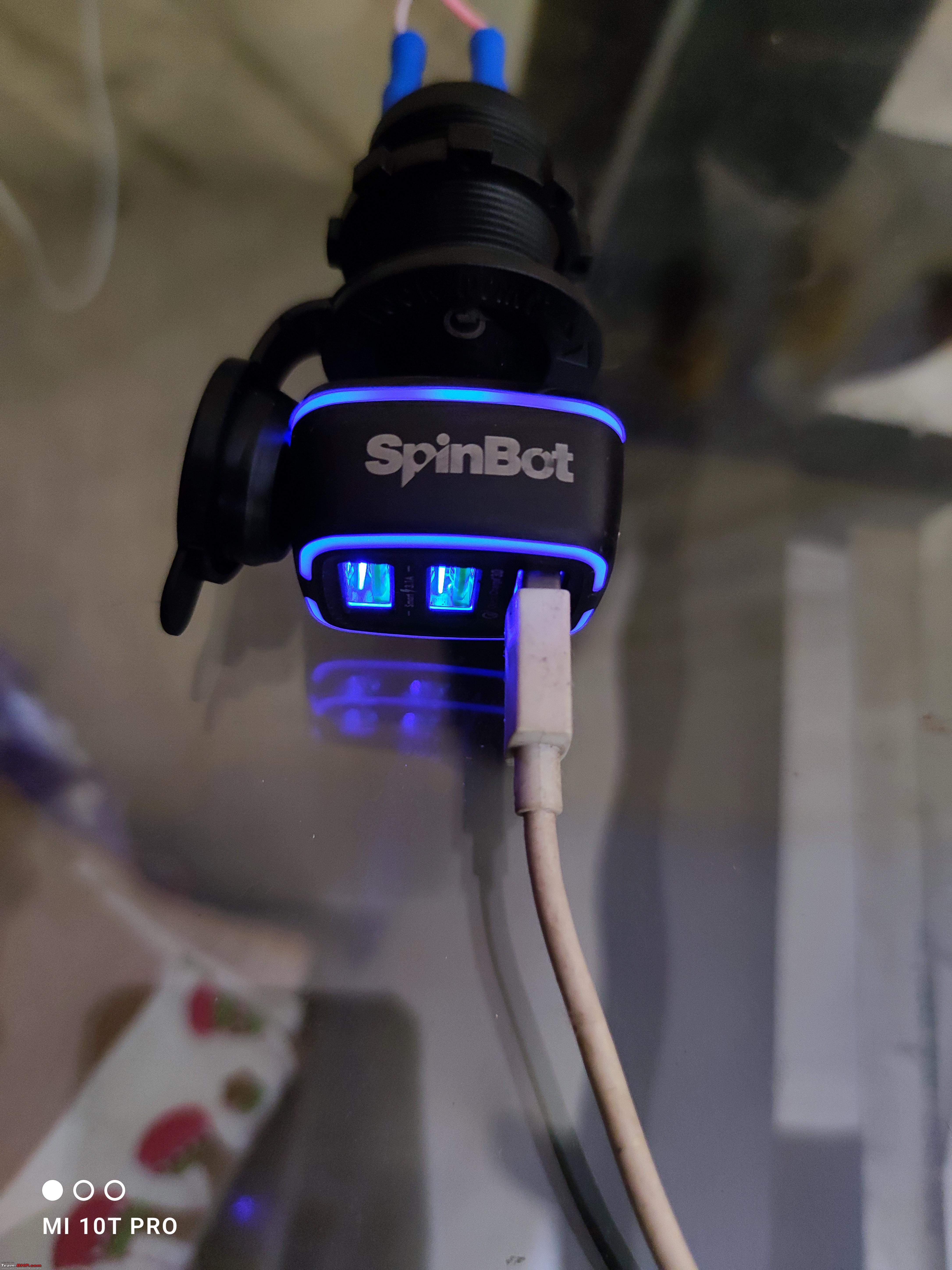 The code is unfinished so I've not made it public yet but if you want to take a look/help you can pm me for access. Lot of things on the to-do list, but for v1 very happy with how this turned out. Feel free to ask any questions! Last edited by Venky03 : 23rd June 2022 at 19:56. |
|
| (36)
Thanks
|
| The following 36 BHPians Thank Venky03 for this useful post: | aargee, abhi802, AdityaDeane, aqualeo2040, AROO7, ashpalio, BoneCollector, capslock, clickdilip, comfortablynumb, Doonite, Fuldagap, gischethans, graaja, GTO, hortons15, InControl, JithinR, K a s h, McLaren Roxx, ndnesh, Nrulz, parsh, Prakritij, pun337, Ravi Parwan, rr_zen, samsag12, SKC-auto, SlowRider, subie_socal, sukhbirST, sumit1609, SYSTEMIZED, TrueDreamer, vzvish91 |
|
24th June 2022, 05:05
| #6 |
| Team-BHP Support  | Re: DIY : Solar Power Conditioning Unit Thread moved out from the Assembly Line. Thanks for sharing! |

| (3)
Thanks
|
| The following 3 BHPians Thank Aditya for this useful post: | graaja, GTO, Venky03 |
|
24th June 2022, 10:21
| #7 | |
| BHPian Join Date: Nov 2019 Location: Navi Mumbai
Posts: 36
Thanked: 30 Times
| Re: Total Cost & Links Quote:
Power supply in the area is really bad. Let me know your suggestions. | |
|
| (1)
Thanks
|

| The following BHPian Thanks sumit1609 for this useful post: | InControl |
|
24th June 2022, 10:31
| #8 |
| BHPian Join Date: Dec 2021 Location: Chandigarh
Posts: 44
Thanked: 160 Times
| Re: DIY : Solar Power Conditioning Unit Amazing setup!! Even I share the view that renewable energy is way forward. But you have demonstrated that unnecessary high capital cost is not required . Most people won't go near an initial setup of 2-3 lacs . If this setup can be done in 27K and readily available in the market , it will be a huge boost to the solar energy adoption especially in a country like India where we have ample sunshine. I am not a technical person but maybe my father help me in this . |
|
| (4)
Thanks
|
| The following 4 BHPians Thank NavtejS for this useful post: | abhi802, InControl, subie_socal, Venky03 |
|
24th June 2022, 10:58
| #9 |
| BHPian Join Date: Dec 2005 Location: bang
Posts: 902
Thanked: 3,292 Times
| Re: DIY : Solar Power Conditioning Unit Definitely an interesting writeup. I have only a small request. If you can post the line / block diagram of the setup, it would definitely help. From what i understand, the arduino setup switches between the grid and the solar panel/ battery-inverter setup to power Fans and Lights right?. It would be of great help if you can post a circuit diagram.  |
|
| (1)
Thanks
|
| The following BHPian Thanks srini1785 for this useful post: | InControl |
|
24th June 2022, 11:23
| #10 |
| Distinguished - BHPian  | Re: DIY : Solar Power Conditioning Unit Outstanding! A hugely impressive DIY job, extremely well done, hats of to you Sir!! Just wondering about a few things. Does India have any rules/regulations on how you hook up your solar panels, via the investor to the grid? When your system provide surplus energy into the grid, what happens to your electricity meter. Old mechanical electricity meters tend to start running backwards! Modern electronic electricity meters tend to have special circuitry to handle and registratie energy provided back into the grid. Here in the Netherlands I get paid for every kW I provide back into the grid. Currently I get the same price per kW generating energy as I am paying. Throughout the year I provide so much energy that my total energy bill is actually zero, other than the fixed cost! How does this work in India? Is this the reason you went off grid? I am not quite sure I fully understand what you meant at the beginning of your post? Jeroen Last edited by Jeroen : 24th June 2022 at 11:25. |
|
| (1)
Thanks
|
| The following BHPian Thanks Jeroen for this useful post: | Doonite |
|
24th June 2022, 11:54
| #11 |
| Newbie Join Date: May 2021 Location: Navi Mumbai
Posts: 4
Thanked: 22 Times
| Re: DIY : Solar Power Conditioning Unit Hi Venky03 Thank you for sharing the details and the thorough writeup on your setup. I find myself in a similar situation, we have a new property, in a newly constructed building on the top floor with access to 150sqft terrace area. As it is a new building in (MMR) and our flat work is till in the initial stage, I was thinking of utilizing the space and setting up solar panels, PCU, battery bank and inverter. Power failures at our location is rare and minuscule in duration, so the main purpose of the solar system would be to reduce the power units used from the grid. As it is a tower and we have a flat I an adverse to a Grid-tie system and heavily leaning towards an Off-grid system. Thought process being, as we get the civil and interior work done we can have dedicated lines drawn to all rooms and have dedicated LED lamps in each area fed by the solar system. I would like to run the refrigerator, and couple of BLDC fans, but this would need a change over from MSEB to solar and vice versa. My questions to you based on your extensive research would be; 1. Your thoughts on the Grid-tie system vs an Off-grid system (Given the stage we are in) 2. What would the estimated cost be for a 150sqft array if done via a professional vs if done DIY. 2. What would your advice be if you we in my shoes, points of consideration and red flags ? 3. Have you done any calculations for a 1ton inverter ac, area and type of setup changes required in the solar power system. 4. Dedicated changeovers for each multi-power device vs a common change over in case of low power. 5. How is the dust accumulation on the solar panels and what is the cleaning schedule you follow? Best Wishes, Puneet |
|
| ()
Thanks
|
| |
|
24th June 2022, 13:31
| #12 | |
| BHPian | Re: DIY : Solar Power Conditioning Unit Quote:
The meter is a bidirectional one measuring intake and outgo of power. My annual power spend is zero or in positive earning since installation. I do not get paid the same price of consumption though, it's on the lower side. I believe choice of on grid / off grid system is use case specific, on grid works best where power outage is infrequent. In such places the grid acts as a vast battery with net metering setup, with no overhead of battery upfront /maintenance costs. | |
|
| (2)
Thanks
|
| The following 2 BHPians Thank Thilak29 for this useful post: | AROO7, Venky03 |
|
24th June 2022, 13:39
| #13 | |
| Distinguished - BHPian Join Date: Jan 2015 Location: Chennai
Posts: 1,916
Thanked: 9,179 Times
| Re: DIY : Solar Power Conditioning Unit Quote:
Every state has its own agencies (called "discoms" for some reason) and they pursue their own policies where home solar is concerned, as they all have varying levels of financial morbidity. Gujarat allows rich credits for customers with on-grid home solar. Tamil Nadu (where I live) provides measly credits. In fact, people opt for off-grid solar straightaway in Tamil Nadu as on-grid power credits are totally not worth the costs involved. I may opt for a hybrid of on and off grid solar in my near future. And i'll ensure no power gets sent to the grid by installing a net-zero device. | |
|
| (4)
Thanks
|
| The following 4 BHPians Thank locusjag for this useful post: | comfortablynumb, Jeroen, SlowRider, Venky03 |
|
24th June 2022, 14:50
| #14 | |
| Senior - BHPian Join Date: Jul 2007 Location: Pune
Posts: 2,070
Thanked: 3,641 Times
| Re: DIY : Solar Power Conditioning Unit Quote:
Example: Erstwhile MSEB (Maharashtra State Electricity Board) was split into 4 co's for holding, generation, transmission & distribution in 2005 - MSEB Holding Company Limited, Maharashtra State Power Generation Company Limited (Mahagenco), Maharashtra State Electricity Transmission Company Limited (Mahatransco), Maharashtra State Electricity Distribution Company Limited (MSEDCL). The xxEDCL is what we retail consumers come into contact with, most of the time. More or less, I believe a similar model is followed throughout the country. | |
|
| (1)
Thanks
|
| The following BHPian Thanks comfortablynumb for this useful post: | locusjag |
|
24th June 2022, 16:31
| #15 | |||||
| BHPian Join Date: Mar 2021 Location: Mumbai
Posts: 239
Thanked: 1,809 Times
| Re: DIY : Solar Power Conditioning Unit Quote:
Quote:
Quote:
 1 - Inverter 2 - 12V Battery 3 - Buzzer 4 - AC Load Readings from the voltage sensor go to A0 and readings from the current sensor go to A1. AC voltage sensor module is missing from this diagram but the input will go to the A2 pin of arduino. I'll also try and put up a flow chart of the switching logic by this weekend. Switching in action (from solar to mains) : Quote:
Quote:
2-You can fit in around 5-8 panels(330wp) and a 2.5KW grid-tied setup will cost you around 1.5 lacs while a off-grid pcu based setup will cost around 1.8-2 lacs. If done via a professional add in another 15-25%. Also if you want to avail the subsidy, you'll have to stick with the specified vendors. 3-Main point of consideration will be your average monthly consumption and deciding the capacity of your system accordingly. Also in case of net metering you'll need to route the cables from your inverter to your meter-box so keep that in mind. Red flags : If the quote is way less than the competition there's a high probability that the agency is earning commission by using poor quality components. Also they'll recommend oversizing the system by 40-50% but 20% will be a sweet spot if you consider ROI. 4-AC requires high amounts of current when starting to cool down the room, the only adjustments required would be to the battery and cables. There are also aircons specifically made for solar applications, you can check them out if interested. 5-Grouping the wiring of all the low power devices like leds & fans and dedicated wiring for high power appliances like air-conditioners, microwave, airfryer, etc. will make it easier for you to manage the loads incase you decide to go off-grid in future. 6-Can't comment about the cleaning schedule because the rain is cleaning up panels on a daily basis as of now. | |||||
|
| (2)
Thanks
|
| The following 2 BHPians Thank Venky03 for this useful post: | aargee, pun337 |
|