| |||||||

| Search Forums |
| Advanced Search |
| Go to Page... |
 |
| Search this Thread |  93,878 views |
 26th July 2018, 14:16
| #1 |
| BANNED Join Date: Nov 2016 Location: Kollam
Posts: 2,018
Thanked: 6,658 Times
| Understanding & troubleshooting Motorcycle Charging Systems This is for @BigBrad and others who're facing charging issues with their motorcycles. Though not as challenging as carburettor jetting, issues with the charging system of a motorcycle can be nerve wrecking especially if you're dependent on the SVC as they may use this ambiguity against you, so I hope to simplify diagnosis with this post. But before that lets do a little bit of learning; Components of Motorcycle Charging System: 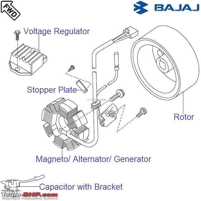 Stator: This is the stationary part of the alternator, the alternator generates AC current. Regulator Rectifier (RR) Unit: This is the part with the heat sink on it, this has two functions i.e to rectify the AC current from the stator and to regulate the charging of the battery. Battery: This is the DC charge repository of the motorcycle, it stores DC current which comes from the RR unit so that the same can be utilized by various electrical components of the motorcycle. Now that we have an understanding of what does what lets get on with the diagnosis; How to Diagnose a Motorcycle Charging System: Step 1: Decode the Wiring Now this is the confusing part for beginners, components of different motorcycles come with different wiring and color coding but the basics remain the same so here goes: 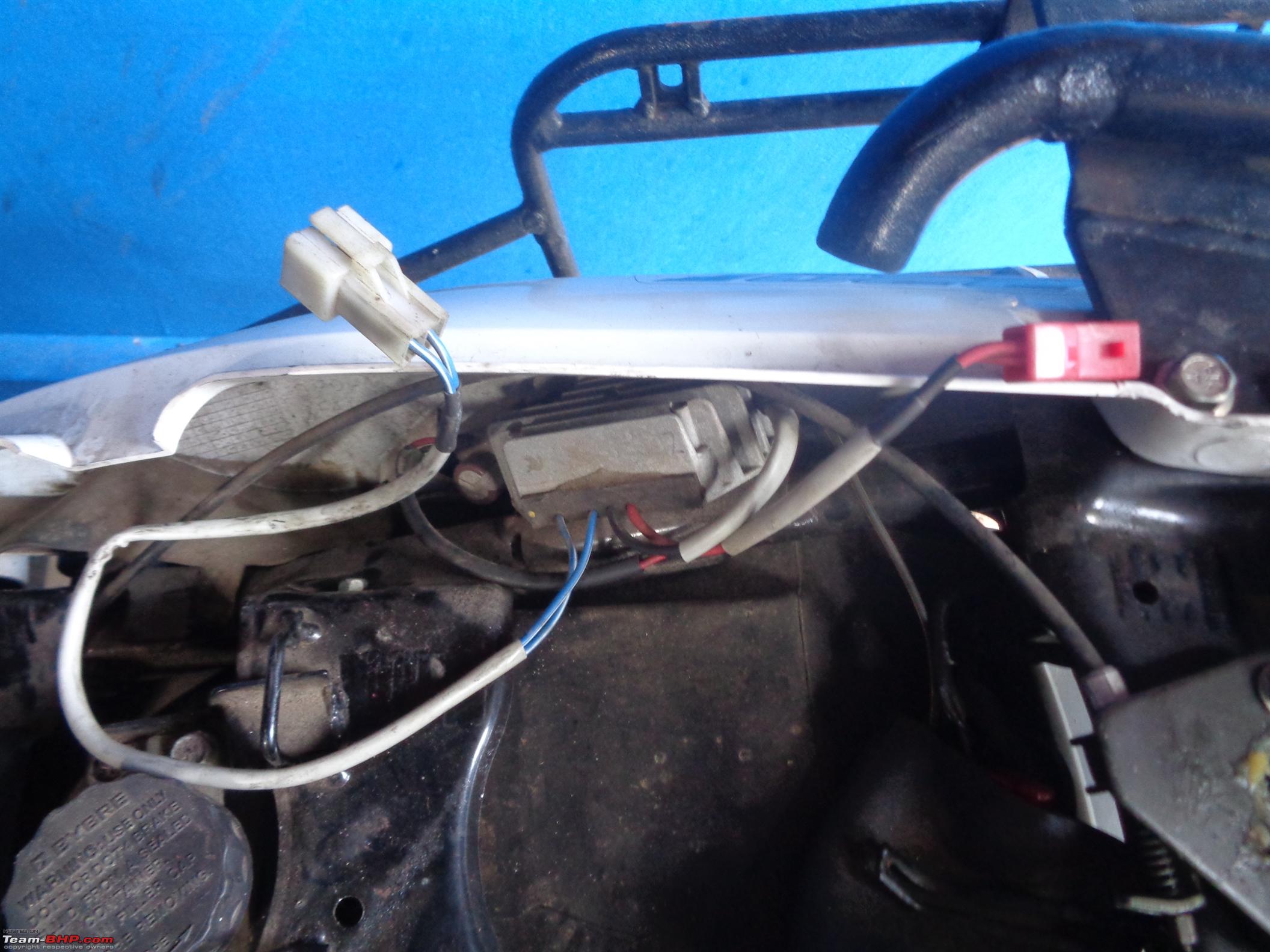 Stator Connector: This is the connector which connects the stator with the RR unit, you can differentiate this from the rest by observing wiring with similar colors. Battery Connector: This connector connects the Battery positive terminal to the RR unit. This varies from motorcycle to motorcycle, some motorcycles come with a single connector with all the pins in place and for some motorcycles there are individual connectors, so if that is the case you would have to determine what color wire does what. 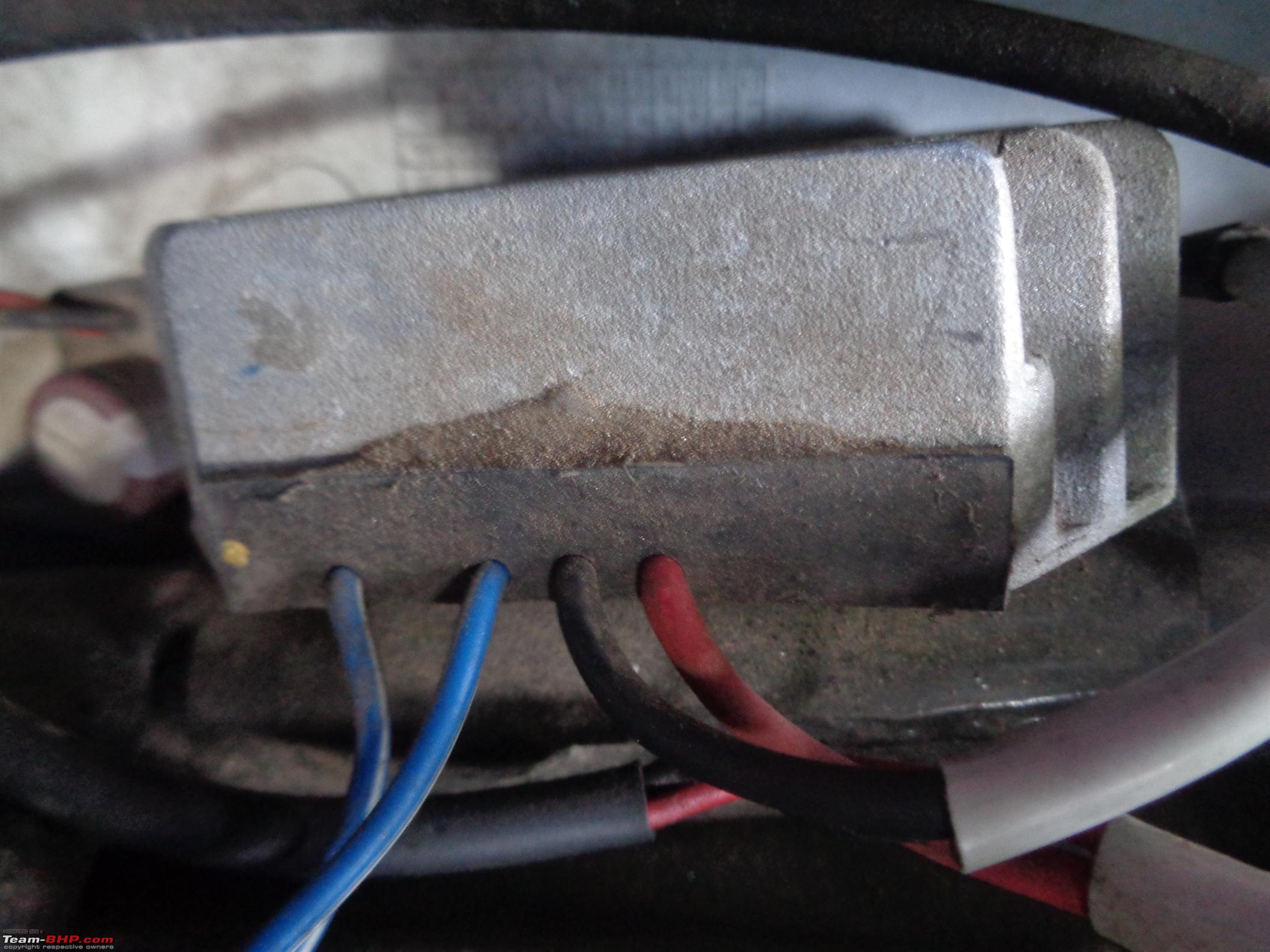 Now coming to the matter of color; Red: "+" Terminal DC Current Black: Grounding i.e "-" Terminal DC Current, hence why the wire goes to a ring connector which is tethered to the RR's mount on the chassis. Blue's(Similar Color Wiring): AC Current. Step 2: Evaluate the Battery  Change the multi-meter's mode to DC and connect the leads to the battery, the positive battery terminal of the battery can be tapped from the Red wire on the wiring side and the negative terminal can be tappet from any metal component as the whole chassis is grounded, in this case I've grounded to the body of the RR unit. 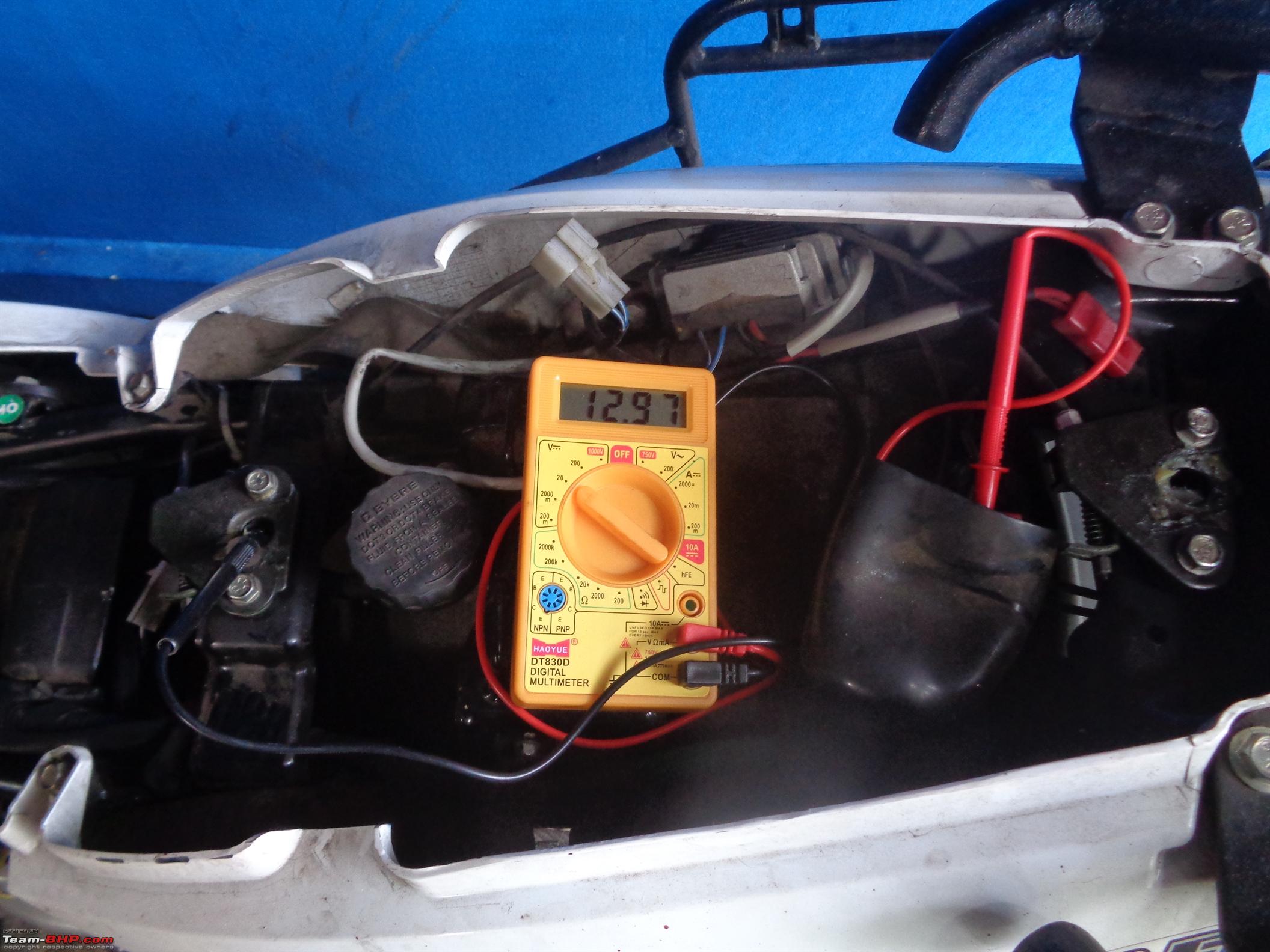 The same result can be obtained if I ground anywhere else on the chassis as well, so go with what is convenient for you. 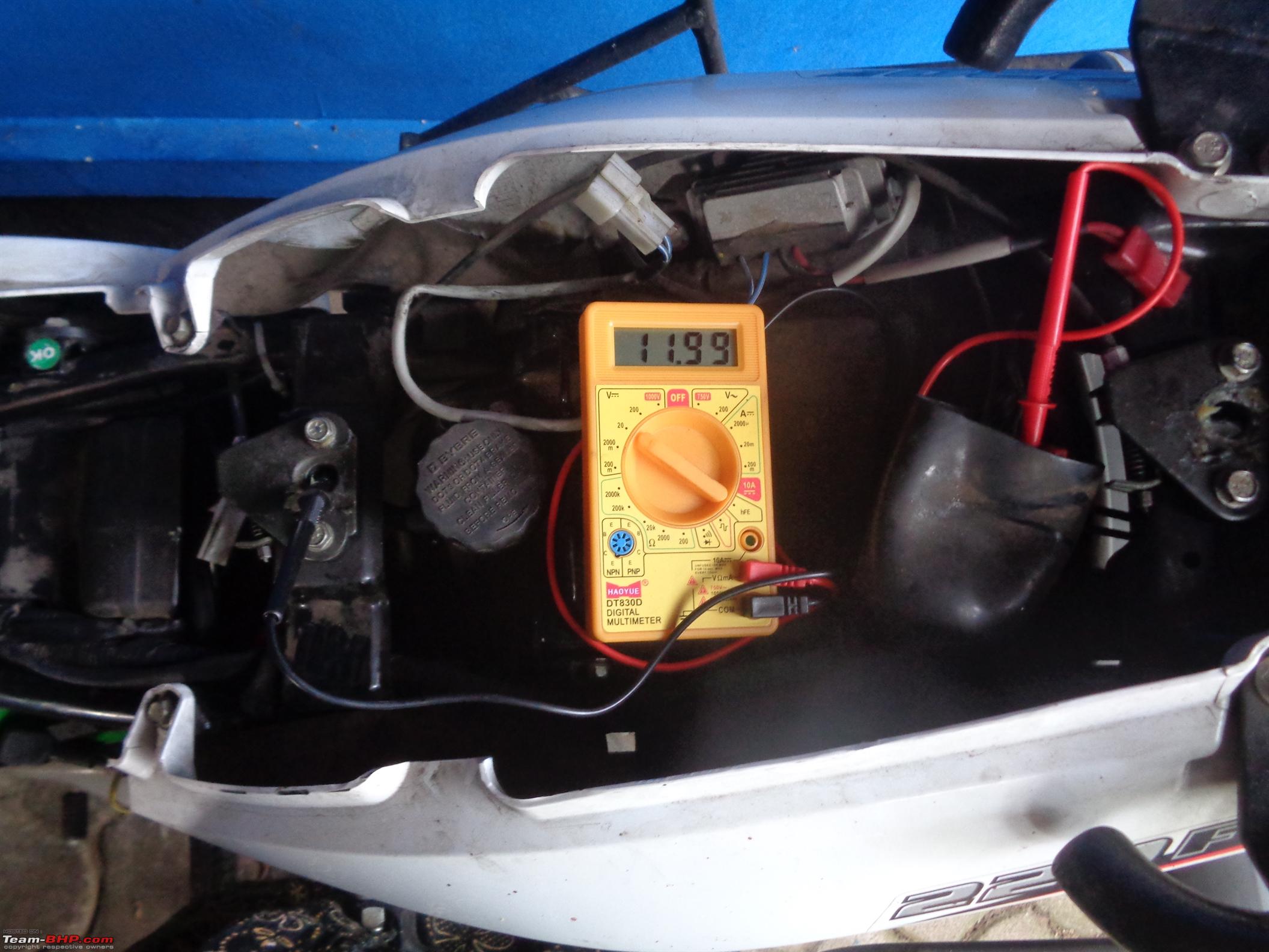 Just because the Battery shows a good reading which ideally would be between 12.50~13.25 Volts that doesn't mean that all is well as it might be surface charge, so you would have to put load on the battery and the component that puts the maximum load on the battery is the starter, so with the spark plug cap off crank the motor and observe for a drastic power drop in battery charge, anything over 9.50 Volts for a few seconds shows that the battery is in good condition, as you can see above while cranking my battery's charge drops to 11.99 Volts. Now since the battery has been checked individually, it's time to check whether the charging system and battery are working as designed, for that with all the connectors hooked up you would have to start the motorcycle and let it run for a few seconds and take a read of the battery;  Ideally you should expect a reading of around 13.50 Volts at idle which means that the battery is getting charged adequately. 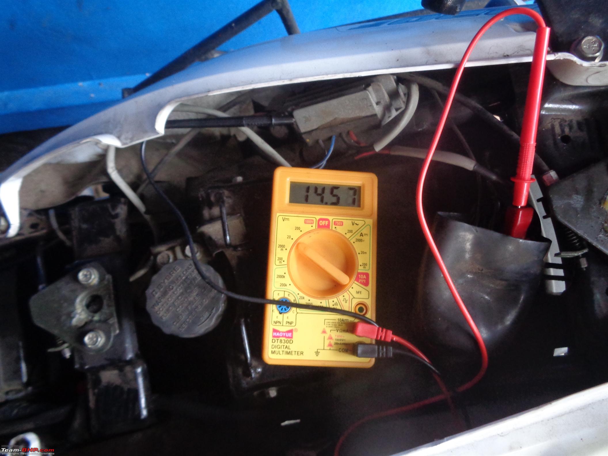 But that is not all that you should look for, at considerable rev's the charge should not go past 14.70 Volts if it does then that means that the RR is faulty and is overcharging the Battery which if not rectified immediately would result in deteriorating the Battery. Once we're done with the Battery, we move on; Step 3: Evaluate the RR Unit Now here we're going to check the continuity so change the multi-meter's mode to continuity/diode and check between one stator line from the RR's side and ground the other, polarity matters here so the multi-meter's Red lead is supposed to ground and whereas the Black lead goes into one stator line from the RR's end at a time, after you've done inspecting both stator wires one after the other you need to make sure that the reading are in the same ballpark, as seen in the below photo's.   If the values are quite far apart then that would mean that the RR unit is not working at its optimum. Step 4: Evaluate the Stator  With the multi-meter still in continuity mode check the continuity between the Stator leads on the Wiring side, if you get continuity then all is well, if not then the Stator is at fault. Now you can go a bit farther and check the output of the Stator, below are my values at idle followed by at rev's but before that you should change the multi-meter's mode to AC Volts.  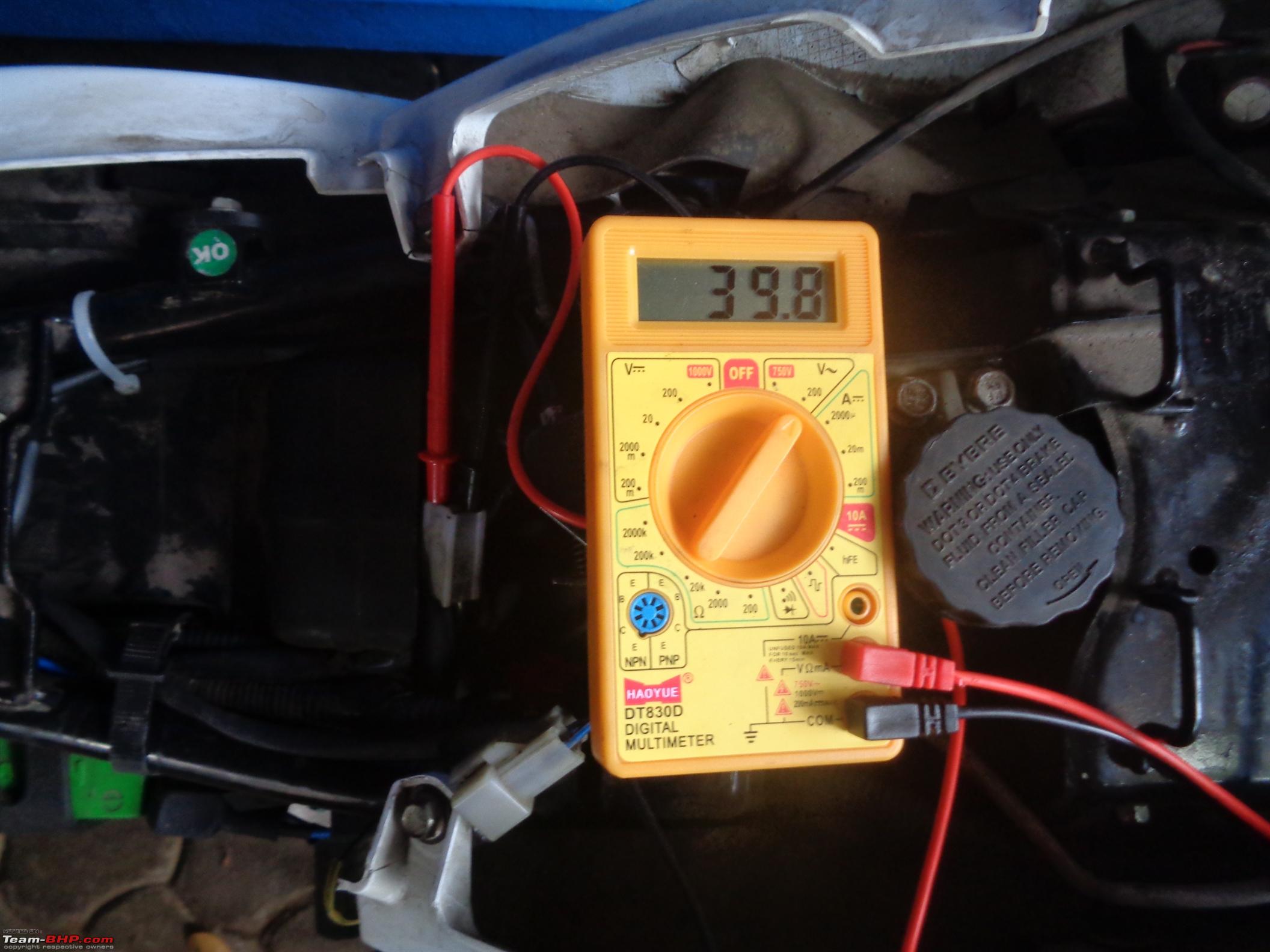 Ideally you may expect a reading of 15 ~ 40 Volts, but that is motorcycle dependent so it is best to refer your workshop manual for the specific range. Now after youve gone through all the steps you know how to diagnose a motorcycles battery as well as its charging system, but before going ahead with that it is best to make sure all your fuses are in order, because most of the time it would be a faulty fuse that would prevent the battery from charging. So that is that, do post your concerns and queries also do share your suggestions as Im no expert on the matter having received no formal education on the same. Ride far and safe. A.P. |

|  (34)
Thanks (34)
Thanks
|
| The following 34 BHPians Thank ashwinprakas for this useful post: | a4anurag, adrian, akmehta, anjan_c2007, arjithin, bblost, BigBrad, Chandrahas, dailydriver, dhruvritzed, docmoya2007, E = mc², govigov, GreaseMonk, GTO, highway_star, InControl, IndigoXLGrandDi, Jaggu, KA18, knightrider_7, Leoshashi, mishraak, N33raj, naveenroy, ObsessedByFIAT, R2D2, rakesh_r, Roy.S, sukiwa, tharian, Torino, unk9ja, vishu2xll |
| |
|
27th July 2018, 12:57
| #2 |
| BHPian Join Date: Sep 2014 Location: Noida
Posts: 344
Thanked: 689 Times
| Re: Understanding & troubleshooting Motorcycle Charging Systems Great post as above buddy, but i'd like to add a few points (I am a manufacturer of Regulator Rectifier and many other bike parts): 1.Apart from AC and battery charging, RR also has a supply for headlight voltage. 2.A poor quality or non working RR tends to give out current at start at handlebar switches 3.All RR's are different in circuit but ever since the AHO(Auto Headlight On) became standard, role of RR has increased. 4.Bajaj changes RR design most frequently |
|
| (10)
Thanks
|
| The following 10 BHPians Thank dhruvritzed for this useful post: | a4anurag, akmehta, ashwinprakas, BigBrad, gauravanekar, govigov, mishraak, N33raj, Roy.S, vishu2xll |
|
27th July 2018, 16:34
| #3 | |||||
| BANNED Join Date: Nov 2016 Location: Kollam
Posts: 2,018
Thanked: 6,658 Times
| Re: Understanding & troubleshooting Motorcycle Charging Systems Quote:
Are there more definitive ways to diagnose a RR unit? Is there a difference in diagnosing a 2 Phase and 3 Phase RR unit? Quote:
I've always been curious of how to convert such commuter motorcycles wiring at the RR end to run the headlights off the battery. Though I've seen a couple of posts regarding AC to DC conversion I still fail to understand the basics. A comparison of wiring between AC/DC motorcycles would also help. Quote:
Quote:
Quote:
 * By DC electrical's I mean that the headlight is powered by battery and by AC electrical's I mean that the headlight is powered by RR unit. | |||||
|
| ()
Thanks
|

|
27th July 2018, 18:44
| #4 |
| Senior - BHPian Join Date: Nov 2009 Location: Pune
Posts: 2,091
Thanked: 3,457 Times
| Re: Understanding & troubleshooting Motorcycle Charging Systems Aah, took me back to 2009 when I had a Honda Unicorn. Converted the electricals from AC to DC. Attaching a few pics. Used the RR unit from Ape Piaggio 3 wheeler. PS- The bike is still running on DC with its new owner. |

| (4)
Thanks
|
| The following 4 BHPians Thank rakesh_r for this useful post: | ashwinprakas, BigBrad, N33raj, R2D2 |
|
27th July 2018, 19:26
| #5 | |
| BANNED Join Date: Nov 2016 Location: Kollam
Posts: 2,018
Thanked: 6,658 Times
| Re: Understanding & troubleshooting Motorcycle Charging Systems Quote:
And I'm a bit confused on the stator wiring part of the conversion as well, please do explain from the basics as I'm an absolute novice as far as electrical's go, I just read and experiment to get things done most of the time. I have a CT100B that I would love to convert to DC, I did considering tapping the brake switch for a 12V DC output but rather than that I feel going for a complete conversion as in your case would be the better option.  Last edited by ashwinprakas : 27th July 2018 at 19:28. | |
|
| (3)
Thanks
|
| The following 3 BHPians Thank ashwinprakas for this useful post: | deep_bang, gauravanekar, rakesh_r |
|
28th July 2018, 20:33
| #6 | |
| BHPian Join Date: Mar 2007 Location: Bangalore / Boise
Posts: 937
Thanked: 1,517 Times
| Re: Understanding & troubleshooting Motorcycle Charging Systems Quote:
| |
|
| ()
Thanks
|
|
29th July 2018, 00:59
| #7 | |
| BANNED Join Date: Nov 2016 Location: Kollam
Posts: 2,018
Thanked: 6,658 Times
| Re: Understanding & troubleshooting Motorcycle Charging Systems Quote:
If its an all out conversion then my understanding so far is that you'd need to float the ground at the stator, ground the pulser coil and then change the RR unit to that of APE or any other DC RR would do as well. I'm waiting for someone whose actually got down and dirty with the same to confirm my understanding, and I would also love to find out how to actually determine the ground at the stator and float it, and also how to determine the pulser coil line and then ground it independently. As far as my experience goes anything related to electrical's on a motorcycle is like sex in the typical Indian household, almost everyone's doing it but they're a little hesitant to speak openly about it. Last edited by ashwinprakas : 29th July 2018 at 01:14. | |
|
| (1)
Thanks
|
| The following BHPian Thanks ashwinprakas for this useful post: | deep_bang |
|
30th July 2018, 09:44
| #8 | |
| Senior - BHPian Join Date: Nov 2009 Location: Pune
Posts: 2,091
Thanked: 3,457 Times
| Re: Understanding & troubleshooting Motorcycle Charging Systems Quote:
https://www.xbhp.com/talkies/univers...ke-all-dc.html | |
|
| (1)
Thanks
|
| The following BHPian Thanks rakesh_r for this useful post: | ashwinprakas |
|
30th July 2018, 10:23
| #9 | |
| BANNED Join Date: Nov 2016 Location: Kollam
Posts: 2,018
Thanked: 6,658 Times
| Re: Understanding & troubleshooting Motorcycle Charging Systems Quote:
My understanding/concerns are; 1. There should be NO continuity between the ground and coils. 2. The two wires that go back to the stator should be connected to either ends of the coil without any possibility of grounding. 3. How is the Pulsar Coil wired, in some instances I see that the Pulsar coil needs to be independently grounded, how do I determine if it needs to be done as such in my motorcycle and if it needs to be done would just grounding it to the case do? Asking because on some bikes I've seen that the Pulsar coil comes with independent wiring in which case I presume that I am supposed to leave it alone. 4. In some specific posts I see that while working with the stator it is advised to not touch the "Ignition Coil", this is something I don't understand, is the reference to the primary ignition coil i.e the one circled in below?  If so, how is the same wired? Is it connected to the coils or does it have independent wiring that leads to the CDI? Hoping someone who'd done the mod would be able to confirm/correct my understanding and also answer my queries so that I can go ahead with the modification with full confidence. As for the RR unit I'm familiar with the wiring so I'd just get myself a Pulsar's RR unit and rewire the pins. Have also posted the query on xBhp, fingers crossed! Last edited by ashwinprakas : 30th July 2018 at 10:26. | |
|
| (1)
Thanks
|
| The following BHPian Thanks ashwinprakas for this useful post: | dhruvritzed |
|
30th July 2018, 15:01
| #10 |
| Newbie Join Date: Apr 2015 Location: Chennai
Posts: 12
Thanked: 11 Times
| Re: Understanding & troubleshooting Motorcycle Charging Systems Nice and indepth techncial information by ashwinprakas and dhruvritzed  Good to see some electrical heads here sharing their practicals with other team members. Do keep us posted with upcoming changes too whenever carried out in your rides. |
|
| (1)
Thanks
|
| The following BHPian Thanks akmehta for this useful post: | ashwinprakas |
|
29th October 2019, 01:10
| #11 | ||||
| BANNED Join Date: Nov 2016 Location: Kollam
Posts: 2,018
Thanked: 6,658 Times
| Re: Understanding & troubleshooting Motorcycle Charging Systems Quote:
Which even at idle speed is adequate enough to charge the battery. Here I presume that the difference between AC volts registered and DC volts provided to the battery is the buffer for additional draw which the RR unit can compensate for, right? If so then yeah, the charging system can take quite some load before discharging the battery, but then I'm uncertain whether what I perceive to be the buffer is actually a loss of Volts resulting from the AC to DC conversion. This is where I get a bit confused. Quote:
I say so, cause my P220 is carbureted and yet comes with a 9Ah battery as it is not equipped with an auto decompressor, compared to the FI 390 and GS. Quote:
Quote:
Cause I used to own a ZMA which had a 18 Pole 3 Phase stator and even with an extra load of 50W, if the motorcycle were to run for a while in bumper to bumper traffic at night the horn would eventually die, unless I rev her up past 5k RPM. Everything including the battery was new since this was a new motorcycle at the time. | ||||
|
| (1)
Thanks
|
| The following BHPian Thanks ashwinprakas for this useful post: | Motard_Blr |
| |
|
29th October 2019, 11:21
| #12 |
| BHPian Join Date: Dec 2005 Location: bang
Posts: 900
Thanked: 3,281 Times
| Re: Understanding & troubleshooting Motorcycle Charging Systems I did not know that thread existed. Thanks to @aswinprakash for the detailed intro. Here goes my 2 paise worth of gyaan. Feel free to point out mistakes. THEORY : I guess almost everyone know the difference between AC and DC. The alternator of a bike / car produces AC and AC only. Any rotating conductor in a magnetic field would produce only a AC since it passes through two poles of a magnet. Hence, the voltage / current always comes in a + and - cycles. There is a fixed relation between the frequency of AC , no of poles and the rpm. F = N*P/120 ( i think ). Where N is rpm, P is no of poles and f is the frequency of AC. In the case of a motorcycle, P is fixed. N and hence F varies. When the bike is idling , the frequency would be lower and as speed increases, the freq increases and the increase in speed also increases the voltage as the voltage is directly proportional to speed. Hence, the observation of increasing voltage with speed in an alternator. PRACTICE : For motorcycles, there are two circuits, one the charging circuit and the other is the firing circuit. The firing circuit is directly fed through the alternator AC it consists of the CDI ( usually under the seat ), the ignition coil ( usually under the tank ) and the plug ( you know where this is ). A simple CDI circuit that i pulled off the internet is given below. One of the exciter ( alternator )coils would supply the AC voltage and it is converted to DC using a diode and this charges a capacitor. A SCR is connected to the trigger pulse (again a coil on the alternator ) which then grounds the capacitor on every firing cycle of the piston movement. The grounding then sets off the ignition coil which discharges through the spark plug. Notice here that the battery has no part with this circuit. The actual circuit would be different since you need to consider the firing advance. This, i guess, is done by a microprocessor based on the rpm of the engine. Bit complicated. The other circuit is the charging and aux circuit which is fed by another branch of the alternator AC circuit which is fed through the RR. Now the RR is nothing but a set of 4 diodes which makes the negative cycles of the AC to positive half of AC. Point is that even after the rectification, the DC is still a half sine wave. This is then sent through a capacitor which changes it to a linear DC ( almost ). It is from this branch that the the battery gets its charging voltage and current and from there goes to the lights ( head, indicators etc ) , horn , etc. Point to note is that a bike can run even without battery but a RR is compulsory as the bulbs and other accessories would fry when connected directly to the alternator voltage. Some theory for you. In all electrical circuits, you don't worry about the current. Its simply that you design the circuit based on the rated voltages and leave the current to the load. That said, you need to design your source to take care of the peak load. |
|
| (2)
Thanks
|
| The following 2 BHPians Thank srini1785 for this useful post: | ashwinprakas, R2D2 |
|
29th October 2019, 11:50
| #13 | ||||
| BHPian Join Date: Sep 2013 Location: Bangalore
Posts: 801
Thanked: 1,590 Times
| Re: Understanding & troubleshooting Motorcycle Charging Systems Quote:
For the sake of this explanation, assume that the alternator maximum output is 130 Watts. Also assume that the maximum continuous load is 100 W (headlamp 60, other small lights 20, ignition 10, miscellaneous 10). As you have noticed, permanent magnet alternators, the voltage increases with speed. So output also increases with speed. But there is also winding resistance which is constant. So effectively it's a balancing act: Effective alternator output = theoretical output - losses When the headlamp is off (subtract 60 W + 20 W), the load might be about 20 W. The output of the alternator is enough to supply the load. With full load at idle, the output of the alternator may no longer be sufficient as the losses are high and this causes the voltage to drop. Quote:
Quote:
That has worked but you risked serious damage to the battery with such high current outputs. The battery internal plates could weaken and fail early. But is this a permanent fix? Quote:
It seems that the Zma stator output was quite limited, probably for cost reasons. To have more output at low speeds, you need higher maximum output. Whether the stator is 3 phase or not is not is not important. In this case, you can either have the stator rewound with thicker wire or upsiwe the battery. Both have practical difficulties before you even consider the warranty. | ||||
|
| (2)
Thanks
|
| The following 2 BHPians Thank Motard_Blr for this useful post: | ashwinprakas, srini1785 |
|
29th October 2019, 20:20
| #14 | |||
| Senior - BHPian Join Date: Jul 2009 Location: Calcutta
Posts: 4,668
Thanked: 6,233 Times
| Re: Understanding & troubleshooting Motorcycle Charging Systems So where do we stand regarding sizing of motorcycle batteries? (For those mystified by the statement above, it is because post 11 is a continuation of this (Major battery issue with the BMW G 310 R and GS! BMW Motorrad India is unresponsive), and there are two schools of thought on sizing motorcycle batteries. Essentially encapsulated as (A) Quote:
Quote:
Quote:
Regards Sutripta | |||
|
| (3)
Thanks
|
| The following 3 BHPians Thank Sutripta for this useful post: | ashwinprakas, gauravanekar, Red Liner |
|
30th October 2019, 09:46
| #15 | |
| BHPian Join Date: Dec 2005 Location: bang
Posts: 900
Thanked: 3,281 Times
| Re: Understanding & troubleshooting Motorcycle Charging Systems Quote:
I would categorize motorcycles into three categories 1. Only kick start commuter bikes. 2. Kick and self start commuter bikes. 3. Club class, self start only bigger touring bikes. For categories 1 and 2, an alternator with RR should be sufficient to START & RUN the bike even without a battery. That said, the performance without a battery would be lousy. For category 3, Battery is compulsory. However, the prime energy source for all three categories is the alternator and not the battery. | |
|
| (1)
Thanks
|
| The following BHPian Thanks srini1785 for this useful post: | Red Liner |
|