| |||||||

| Search Forums |
| Advanced Search |
| Go to Page... |
 |
| Search this Thread |  61,662 views |
 7th July 2020, 19:21
| #1 |
| BHPian Join Date: Apr 2020 Location: Pune/Oxford
Posts: 99
Thanked: 631 Times
| Aerodynamics, simulations and the Tesla Model S Enzo Ferrari had once said "Aerodynamics are for people who can’t build engines". With due respect to the man and the circumstances in which he made the above statement, a quick look at today's Ferrari 488 - or any decent production car - will show how ingrained aerodynamics is in the design of today's automobile and how far we have come from 1960 (when the above statement was made). It's one of the few factors that - by itself - affects three primary performance parameters of a car - top speed, handling and fuel consumption/range. I work with fluids in an engineering environment and performing simulations to understand the flow is a big part of my job. It’s exciting to see how a correctly placed tiny design feature can have a massive impact on the flow around it. For example, a properly placed flat plate just 7 cm in width can make a big difference in maintaining traction at high speeds. Place it incorrectly and the fuel consumption will go up with no specific benefit at all. So I used some of my free time exploring the flow around a Tesla Model S. I also simulated some generic aero improving accessories to see the effects they may have on the car and I’d like to share some observations that I found interesting. I have broken this write-up into the following sections:
So grab your coffee and buckle up! 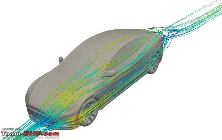 Last edited by MegaWhat : 10th July 2020 at 15:34. |

|  (56)
Thanks (56)
Thanks
|
| The following 56 BHPians Thank MegaWhat for this useful post: | --gKrish--, Aditya, akshay380, akshay386, amit_purohit20, AVIS, Bibendum90949, BlackPearl, bsdbsd, Dani7766, dealer, deep_behera, d_himan, frozen.ash, GKR9900, GTB, GTO, Hayek, hmansari, hs_maverick, KPR, kptraveller, mallumowgli, mohansrides, Night_Fury, Prakritij, quickdraw, RBalaM, RBR, Rehaan, Researcher, RoadSurfer, samy1117, sarathlal, sgmuser, sharktale, Shreyans_Jain, Simat, skchettry, Slick, SS-Traveller, SuhairZain, tchsvy, Teesh@BHP, The Rationalist, Thermodynamics, Turbanator, Turbohead, V.Narayan, v1p3r, Varun_HexaGuy, vtecblast, warrioraks, wheelguy, WhiteKnight, whitewing |
| |
|
7th July 2020, 19:32
| #2 |
| BHPian Join Date: Apr 2020 Location: Pune/Oxford
Posts: 99
Thanked: 631 Times
| Re: Aerodynamics, simulations and the Tesla Model S But first, a quick refresher on the basics of aerodynamics The next time you get into your car, let your brain run wild and imagine that there is a set of weightless airplane wings strapped on the roof of your car. While you are at it, also imagine that you have a parachute strapped to the boot of your car. You proceed to take your car out on the open road and pick up pace. And just like the wings on an airplane make it take-off from the ground, the wings on your car want to lift you off the road as your car picks up speed. In simple terms, what you experience there is lift. And as a parachute tends to slow the rapid descent of objects as they fall, the parachute attached behind your car tries to slow you down as well. In simple terms, that is drag. Wing on the roof: tends to lift the car off the road --> Lift Parachute on the cars boot: tends to slow the car down --> Drag A more technical definition of lift and drag is as below: Lift: Component of aerodynamic force that acts perpendicular to the oncoming flow. Drag: Component of aerodynamic force that acts along the oncoming flow.  Components of aerodynamic force acting on a car To properly identify and control the lift and drag acting on the car, we define a coefficient of lift (Cl) and a coefficient of drag (Cd). These coefficients are a reflection of the shape and size of the car. Larger the Cl, more is the tendency to take off from the road. Larger the Cd, more is the fuel you need to burn to overcome this drag. Cd is only positive, while Cl can be either positive or negative. Positive Cl implies a force that tends to lift the car away from the road. Negative Cl implies a force that pushes the car towards the road, increasing traction. Ideally, we want a high negative Cl that increases traction and a small Cd to have minimal power consumption. For the technically inclined, here's the definition of Cl and Cd for a car: Cl = (2*Lift force)/(air density * velocity * velocity * frontal area) Cd = (2*Drag force)/(air density * velocity * velocity * frontal area) Power required to overcome drag = Drag force*Velocity A generic sedan has a Cl around 0.28 and a Cd around 0.35. That means a generic sedan with a frontal area similar to a Tesla Model S will experience forces as follows: At 30 kmph: Lift = +2.8 Kg, Drag = 3.6 Kg; Power required to overcome drag = 0.4 HP At 60 kmph: Lift = +11.4 Kg, Drag = 14.2 Kg; Power required to overcome drag = 3.1 HP At 120 kmph: Lift = +45.5 Kg, Drag = 56.9 Kg; Power required to overcome drag = 24.9 HP It is important to note that lift and drag are proportional to the square of the car speed. And the power required to overcome drag is proportional to the cube of the car speed. This means that the drag & lift that the car experiences at 120 kmph is 4 times the drag & lift it experiences at 60 kmph. And it needs 8 times the power to overcome drag at 120 kmph as compared to 60 kmph. Last edited by MegaWhat : 10th July 2020 at 14:10. |
|
| (49)
Thanks
|
| The following 49 BHPians Thank MegaWhat for this useful post: | abhijith, Aditya, akshay386, alpha1, amit_purohit20, AVIS, BlackPearl, dealer, deep_behera, frewper, frozen.ash, GTO, Hayek, Jeroen, jnanesh, JoshMachine, KPR, mallumowgli, Night_Fury, NPX, pavanmadhini, Prakritij, rajvardhanraje, RBalaM, Rehaan, Researcher, sgmuser, Simat, Sk8r, skchettry, Slick, Sran, SS-Traveller, ssenhyd, Stiggy_205, SuhairZain, Sutripta, tchsvy, Teesh@BHP, Thermodynamics, Turbanator, Turbohead, turbospooler, V.Narayan, v1p3r, viXit, vtecblast, wheelguy, whitewing |
|
7th July 2020, 19:44
| #3 |
| BHPian Join Date: Apr 2020 Location: Pune/Oxford
Posts: 99
Thanked: 631 Times
| Re: Aerodynamics, simulations and the Tesla Model S What is flow separation? Flow separation is something we will be referring to later, so let's quickly see what it means. Imagine that you're cruising in your car at 90 kmph on an empty 4 lane road. The road is straight for now so you're cruising comfortably. But out of the blue, you encounter a sharp 90 degree turn. It's tough to hold on to the road and take that turn and stay attached to the road, despite hard braking. So you end up going straight and off the road. Thankfully there's some some soft grass on the sides of the road and it slows you down and there's no damage to life or property. In aerodynamic terms, your car "separated" from the road as it stopped following the road. Along similar lines, when air stops following the shape of a body, we say that the flow has separated. For example, when you hold a circular glass sideways under a tap, you’ll see that the water follows the circular shape upto a point, but then stops following the glass and leaves the glass surface in a rather turbulent state. That is flow separation. 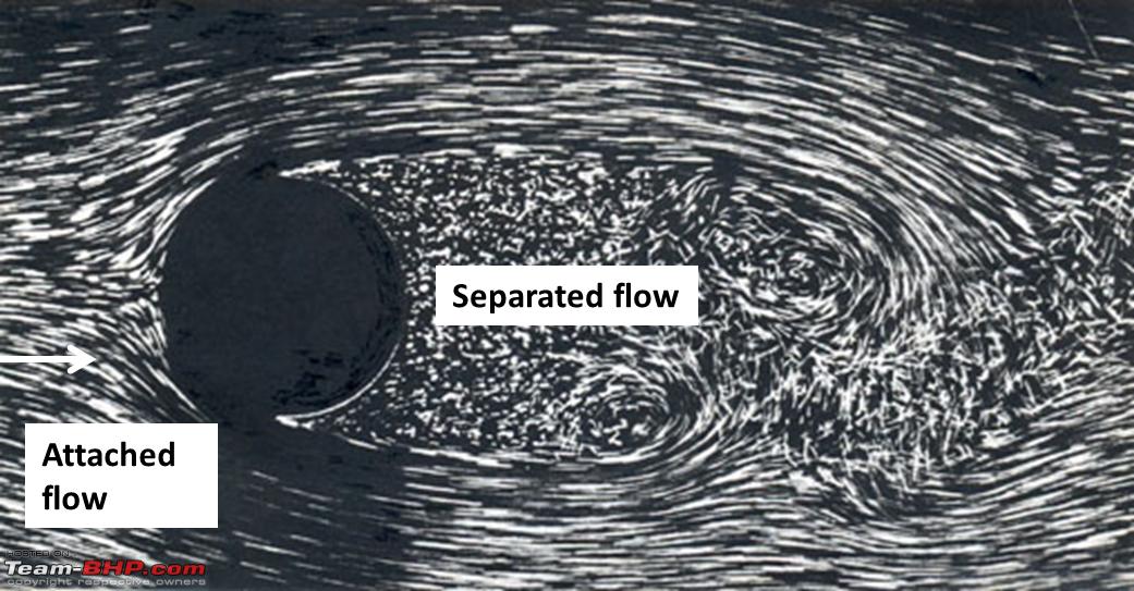 Flow separation around a cylinder A point to note is that once your car has left the road, it does not matter if the road after the point of "separation" is straight or curved or broken, as the car is no longer "attached" to the road. Similarly, once the flow has separated from the surface of an object, the shape of the object after the point of separation does not matter as the flow is not attached to the surface to follow it. As compared to separated flow, an attached flow usually gives lower drag and higher lift, and in most cases (especially flow over a car) air will tend to separate at one point or another. In that case, controlling the point of flow separation is better than letting it separate by itself. This is one of the reasons we have spoilers on our production hatchbacks – to ensure that the flow separates exactly where we want it to at all road speeds. Any movement in this point of separation over different speeds can lead to unexpected variation in how the car handles at high speeds. For example, if at 80 kmph the flow separates on your car near the A-pillar, the car will not experience a lot of lift and you'll feel planted to the road. But if at 100 kmph, suddenly the flow is attached on the roof and separates only at the C-pillar, the car will suddenly experience a jolt of lift as it goes from 80 to 100 kmph and the ride will feel slightly unsettled as the car becomes "floaty". The spoiler on the hatchback ensures that the flow is attached to the roof and consistently separates only as it leaves the spoiler itself - at all speeds. Last edited by MegaWhat : 10th July 2020 at 20:48. |
|
| (43)
Thanks
|
| The following 43 BHPians Thank MegaWhat for this useful post: | --gKrish--, Aditya, akshay386, anToNIcHeN, AVIS, BlackPearl, carthick1000, dealer, deep_behera, d_himan, frozen.ash, GTO, Hayek, hmansari, Jeroen, KPR, mallumowgli, Night_Fury, NPX, Prakritij, rajvardhanraje, RBalaM, Rehaan, Researcher, sgmuser, Shreyans_Jain, Simat, Sk8r, skchettry, SS-Traveller, ssenhyd, SuhairZain, Sutripta, tchsvy, Teesh@BHP, The Rationalist, Thermodynamics, Turbanator, Turbohead, V.Narayan, vtecblast, warrioraks, wheelguy |
|
7th July 2020, 19:49
| #4 |
| BHPian Join Date: Apr 2020 Location: Pune/Oxford
Posts: 99
Thanked: 631 Times
| Re: Aerodynamics, simulations and the Tesla Model S So what all has been simulated? Apart from the stock Tesla Model S, I tried out a few accessories that work on the air around the vehicle. But why the Tesla Model S? Why not any other car There are a few specific reasons why I picked up this particular vehicle:
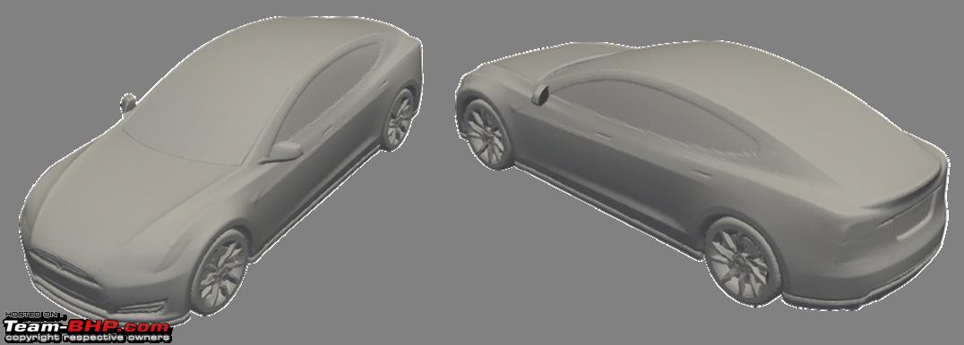 Simulated stock Model S Coming to the accessories, I did not have access to the Tesla branded spoiler of course, or details of other accessories, so I have simply created an approximate geometry of these with dimensions approximately in the same ballpark. Images for reference below.
 Simulated accessories Last edited by MegaWhat : 10th July 2020 at 14:10. |
|
| (33)
Thanks
|
| The following 33 BHPians Thank MegaWhat for this useful post: | Aditya, akshay386, alpha1, AVIS, BlackPearl, deep_behera, frozen.ash, GTO, hmansari, Jeroen, mallumowgli, Night_Fury, Prakritij, rajvardhanraje, RBalaM, Rehaan, Researcher, sgmuser, Simat, Simhi, skchettry, SS-Traveller, ssenhyd, Sutripta, tchsvy, Teesh@BHP, The Rationalist, Thermodynamics, Turbanator, Turbohead, turbospooler, V.Narayan, wheelguy |
|
7th July 2020, 20:05
| #5 |
| BHPian Join Date: Apr 2020 Location: Pune/Oxford
Posts: 99
Thanked: 631 Times
| Re: Aerodynamics, simulations and the Tesla Model S Results: Lift, drag and power required to overcome drag Below are the results for the stock Model S and other add-ons. Do note that these values should be used only for getting a general idea and for comparison only among each other as they are from the same set of simulations. It is not ideal to compare these to any other number you may find elsewhere as the simulation or testing methods may vary. Cl is considered positive when the force tends to lift the car up, away from the road. Cl is considered negative when it tends to push the car into the road. Ideally, we want a high negative Cl to maintain traction while keeping Cd low.  Values of Cl & Cd for the stock Model S and Model S with other accessories Lets see how much force (in Kgs) to expect at different speeds and what is its effect on the power required to overcome drag (in HP). 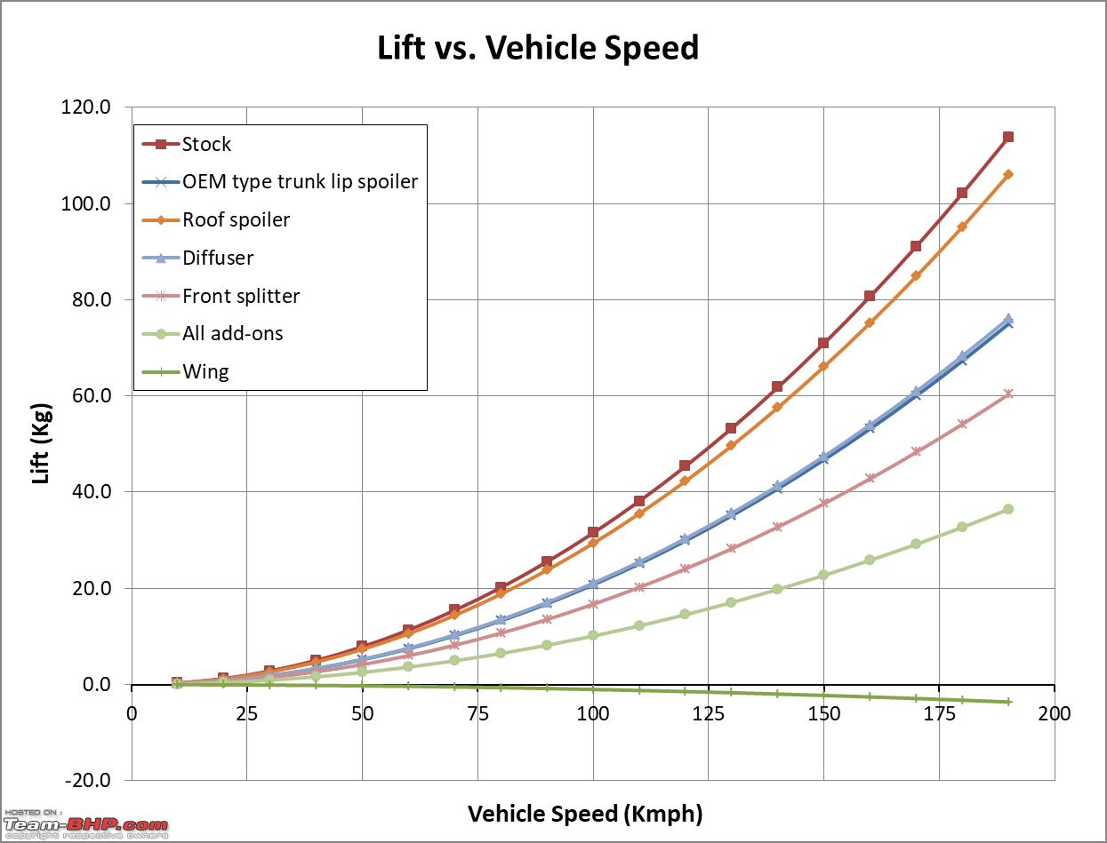 Variation of lift with car speed 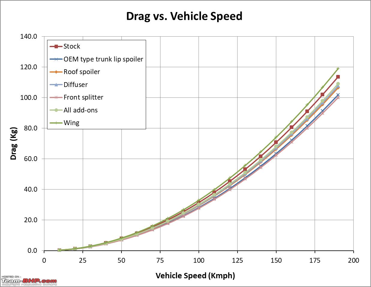 Variation of drag with car speed 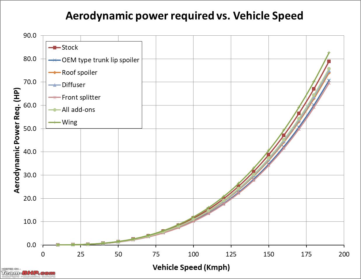 Power required to overcome drag at different car speeds Here are some of my observations: On lift:
On drag:
So for a road vehicle, how much lift is safe, and when do we consider it to be dangerously high? I could not find a clear answer online with a basic search. However, I believe it depends on a few other variables such as the weight of the car and the suspension setup. For a car as heavy as the Model S, experiencing an upward lift of 80 Kg (at 160 kmph) might not be a big deal - it is a mere 4% of the kerb weight of ~2000 Kg. There is still ~1920 Kg weight acting on the tyres and helping maintain traction. However, if a car with a kerb weight of ~900 Kg experiences 80 Kg of upward lift, I believe we can expect some adverse impact on handling as almost 9% of the cars weight is taken off the tyres. Would like to hear comments on this. Last edited by MegaWhat : 10th July 2020 at 20:21. |
|
| (43)
Thanks
|
| The following 43 BHPians Thank MegaWhat for this useful post: | Aditya, akshay386, alpha1, ampere, AVIS, BlackPearl, classiccurves, Dani7766, dealer, deep_behera, DicKy, frozen.ash, GTO, Hayek, Jeroen, jnanesh, mallumowgli, Night_Fury, NPX, pavanmadhini, PGA, rajvardhanraje, Rambo-RS, RBalaM, Rehaan, Researcher, sgmuser, Shreyans_Jain, Sk8r, skchettry, Sran, ssenhyd, SuhairZain, Sutripta, tchsvy, Teesh@BHP, The Rationalist, Thermodynamics, Turbohead, V.Narayan, vtecblast, warrioraks, wheelguy |
|
10th July 2020, 15:27
| #6 |
| BHPian Join Date: Apr 2020 Location: Pune/Oxford
Posts: 99
Thanked: 631 Times
| Re: Aerodynamics, simulations and the Tesla Model S Results: Effect on traction - Front wheels vs. rear wheels Another aspect that we look into is the moment due to these aerodynamic forces. After all, a net positive lift is one thing, but where exactly on the car is it acting - the front of the car or the rear? Imagine that your car is kept on a see-saw, in such a manner that the center of gravity is right above the pivot of the see-saw. In that case, the car should be stable and not fall either side. Next, imagine that a gigantic fan is blowing air at your car from the front. To keep the see-saw balanced, the aerodynamic lift generated by the front half and rear half of the car should be equal. Otherwise, the the arrangement will drop towards the side that has less aerodynamic lift. But achieving this balance is easier said than done. For example, when we attach a rear wing, a lot more downward force is experienced by the rear wheels as compared to the front wheels and we may experience reduced traction from the front wheels at high speeds. This situation is reversed if we only attach a front splitter in which case we may lose traction on the rear wheels at high speeds, while maintaining traction on the front wheels. It is important to know which wheel is going to give up traction first. Below is the variation in load on the front and rear axle with increasing speed for various accessories and the stock car. We should keep the kerb weight of ~2000 Kg in mind when looking at these numbers. Positive load values imply a tendency to lift away from the road. Negative load values imply being pushed into the road. 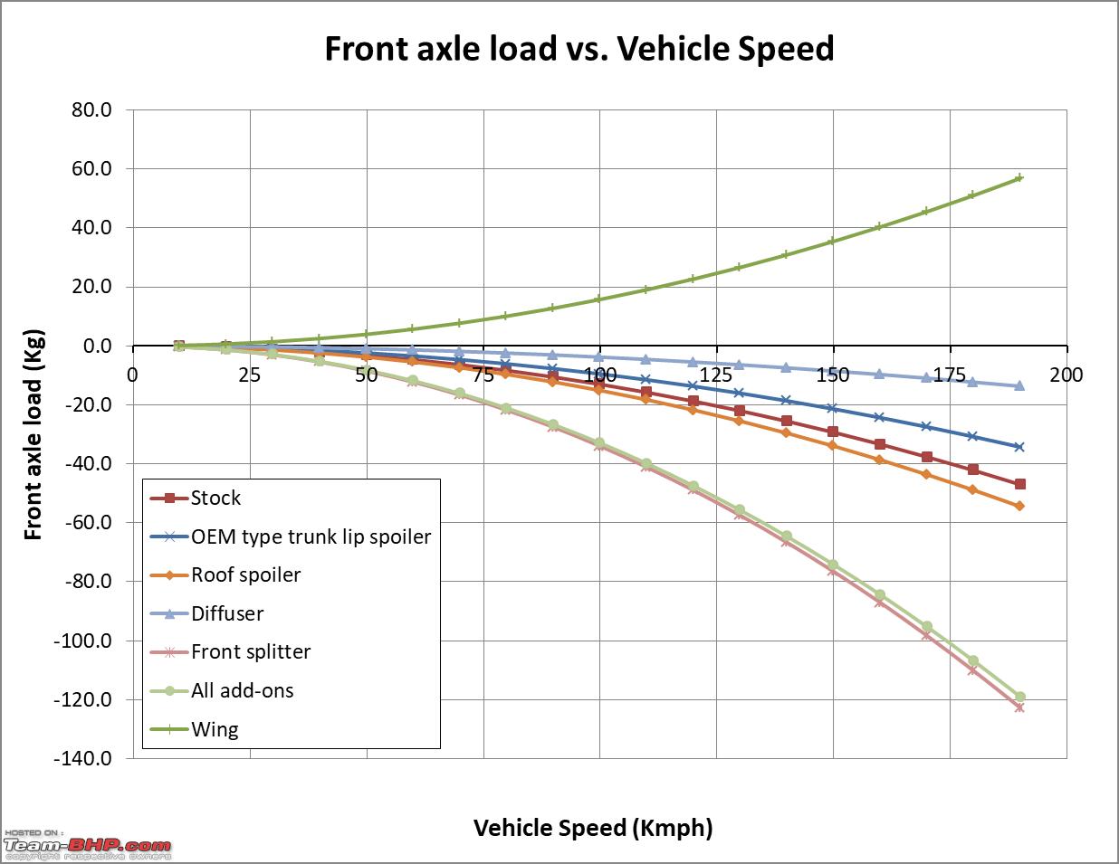 Variation of load on front axle at different speeds 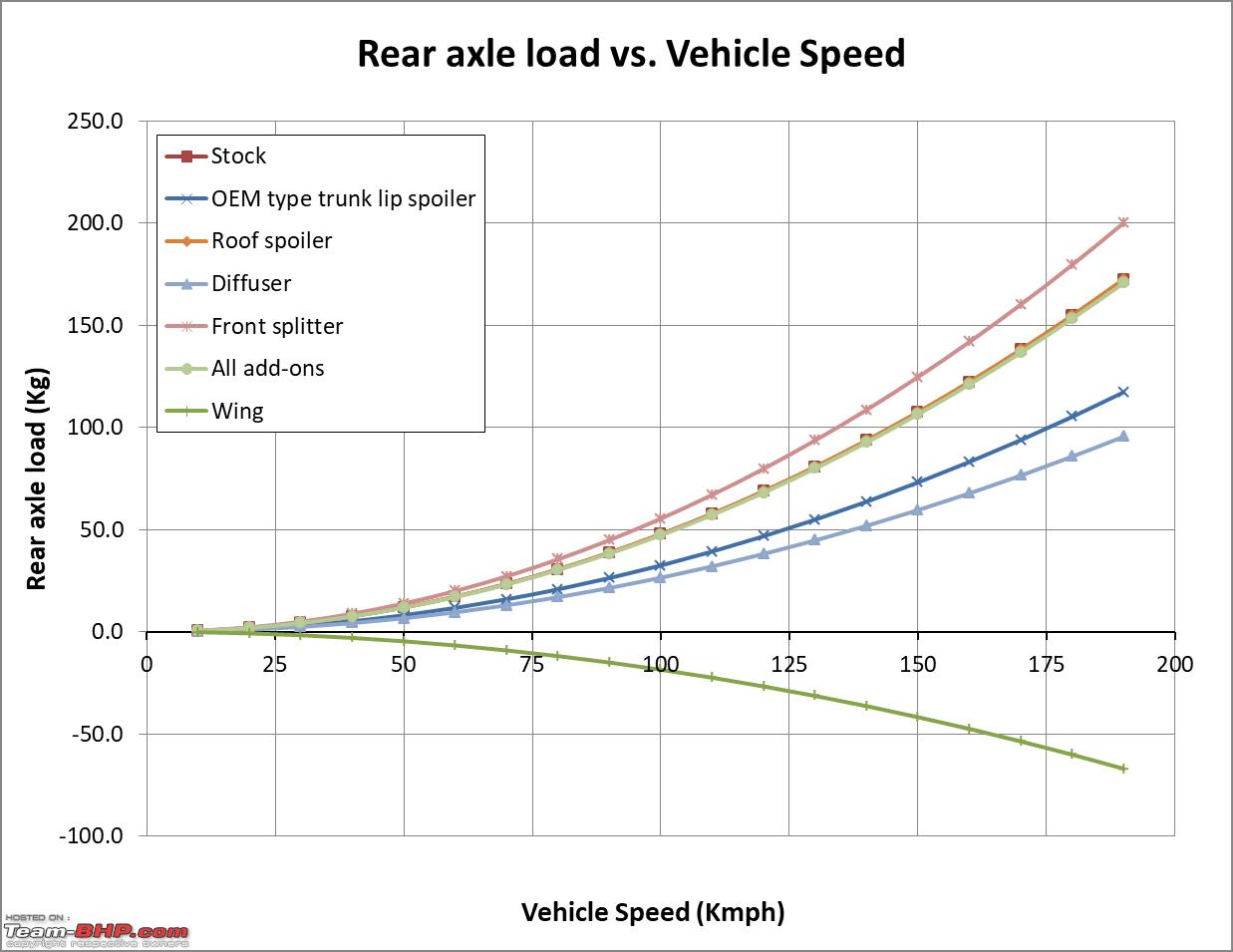 Variation of load on rear axle at different speeds These plots show that for the stock Model S and all accessories except rear wing, with increasing speed, traction increases on the front wheels while traction is lost on the rear wheels. This means that for all accessories except rear wing, most of the positive lift is generated by the rear of the car. This tendency is strongest with the front splitter and least with the diffuser. The numbers are interesting. At 150 kmph, the front axle of the stock Model S experiences a downward force of 29 Kg, while the rear axle experiences an upward lift of 107 Kg. So as the speed picks up, it is the rear of the Model S that will give up traction first. That makes sense as at least there will be control over the steering through the front wheels. For the front splitter, at 150 kmph, the front axle experiences a downward force of 76 Kg, while the rear axle experiences an upward lift of 125 Kg. Addition of a rear wing reverses this trend and we see that with with increasing speed, the car will experience increasing traction on the rear wheels while reducing traction on the front wheels. However, the numbers are more balanced in this case. For example, at 150 kmph, the car with the rear wing imposes an upward force of 35 Kg on the front axle and a downward force of 42 Kg on the rear axle. The diffuser gives the most balanced axles, along with a decent reduction in lift as the difference between the loads experienced by the front and rear axles is the least with the diffuser. Last edited by MegaWhat : 10th July 2020 at 20:52. |
|
| (29)
Thanks
|
| The following 29 BHPians Thank MegaWhat for this useful post: | Aditya, akshay386, AVIS, BlackPearl, classiccurves, dealer, GTO, Hayek, hmansari, Jeroen, mallumowgli, Night_Fury, rajvardhanraje, Rambo-RS, RBalaM, Rehaan, Researcher, sgmuser, Shreyans_Jain, skchettry, Sran, SuhairZain, Sutripta, tchsvy, Teesh@BHP, Thermodynamics, Turbohead, V.Narayan, wheelguy |
|
10th July 2020, 15:29
| #7 |
| BHPian Join Date: Apr 2020 Location: Pune/Oxford
Posts: 99
Thanked: 631 Times
| Re: Aerodynamics, simulations and the Tesla Model S Results: Flow behaviour The next aspect is understanding why do these add-ons behave the way they do? So we look at the streamlines and the drag generating regions around the car. Streamlines essentially show the path followed by the air as it flows across the domain. As the car goes through air, there will be regions where the energy of the air has been reduced due to the car's presence. These can be referred to as drag generating regions and are visualised using what is known as total pressure coefficient. It is a reflection of the total energy contained within a fluid element in the domain. A region where this total energy has been reduced to zero is a reflection of the drag generating areas. A generic sedan also produces regions of swirling flow – called vortices - in certain areas around the car such as the A-pillar (where the flow interacts with the cabin) and near the C-pillar as well (where the flow leaves the cabin and interacts with the trunk). Vortices are interesting features and can be thought as like a local mini cyclone. These create drag and also some noise but can also help in mixing of the flow around it's vicinity - similar to how stirring a glass of lemon juice needs energy but ensures that all the sugar is well mixed up.  Vortex structures around generic automobiles (Ref:https://mechanixillustrated.technica...-aerodynamics/) 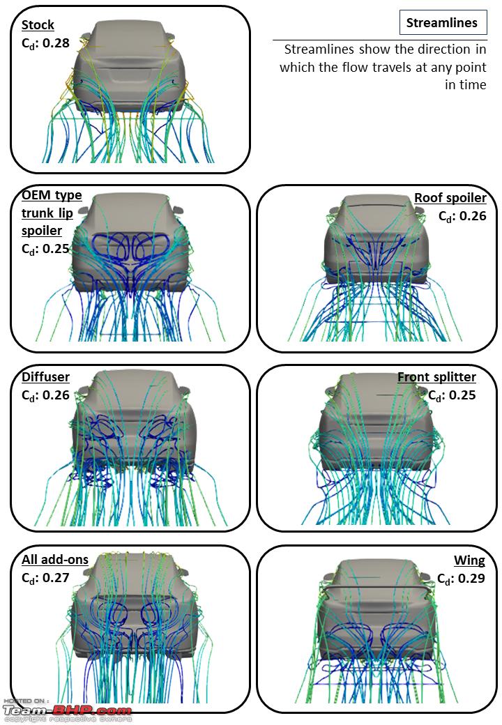 Streamlines seen from rear of the vehicle 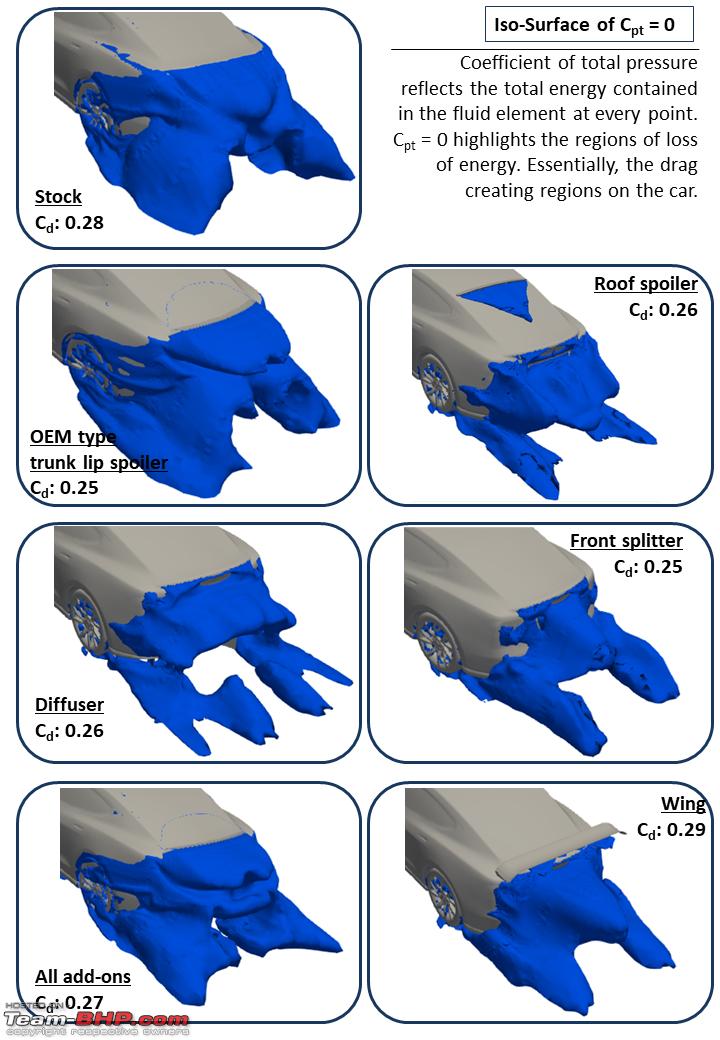 Drag creating regions around the Model S I’m not an expert in automobile aerodynamics and I can be way off in my understanding of the flow features as I have listed below. If I’m interpreting something in a wrong manner or missing out on something, I’d really appreciate if someone more experienced points it out. Remember the swirling vortices that I mentioned earlier? You can see their effects well on the streamlines. The swirling of these vortices can potentially bring in high energy air (that is otherwise away from the car) and mix it with the low energy air closer to the car - thereby increasing the energy of the flow in these regions, leading to a slight reduction in drag. The stock Model S seems to be designed to use the vortices well. The streamlines show some high energy flow from the sides of the car flowing into the rear of the car which is among the primary drag creating regions. The trunk lip spoiler further enhances such mixing and the vortices further cut into the drag creating region of the car, reducing drag a little bit more. The roof spoiler creates an extra region of drag generation near itself, but it seems to slightly alter the position of the larger vortices, leading to a marginal reduction in drag. The diffuser pumps in a lot of high energy air directly into the drag creating region, reducing drag. The front splitter essentially amplifies the aerodynamic effect of the cars exterior by moving a lot more air on top of the car than under it, so the mixing due to the vortices is enhanced as well. The rear wing adds its own drag creating regions and reduces the strength of the vortices around the car, thereby increasing net drag. Let’s look at streamlines in the cross-section below.  Streamlines along the length of the Model S The trunk lip spoiler effectively separates the air at the trunk lip and moves the air upwards, away from the road, reducing lift. The diffuser does the same and the wing does so more effectively. The front splitter reduces the amount of air going under the car and improves the effectiveness of the stock diffuser to bring about an upward movement of air as it exits the rear of the car. A combination the front splitter, diffuser and trunk lip spoiler effectively pumps the air upwards and reduces lift. A spoiler is meant to cleanly separate the flow and the roof spoiler does this job well. It leads to separation of flow and alters the shape of the car (as seen by the air) drastically. Note that once the roof spoiler has separated the flow, the air does not follow the shape of the rear glass or the trunk. This means, a trunk lip spoiler placed behind a roof spoiler is more or less useless. However, I do see some photos of cars sporting both of them together. More often than not, that’s a money spending activity, nothing more. Overall, the Tesla has been very carefully engineered when it comes to aerodynamics which is neat for a production car. It will be a good benchmark for others to learn as well. We also see that well designed and well integrated accessories can be helpful at speeds above ~100-120 kmph as well, at least in terms of improving handling if not reducing drag. I’ll keep on adding other simulations to this thread as and when I’m able to do them. I’d like to run some simulations on the cars sold in India or any add-ons that we have available here. But it’s tough to find good virtual models that can be used. So if someone here has a good 3D scanner, some free time and can provide a closed 3D stl model of the car, I’m game  . .A word on simulations & accuracy Using computers to simulate fluid flow is known as Computational Fluid Dynamics or CFD. It involves numerical methods that break down complex equations into a manageable form and solve them in an iterative manner. CFD methods and processes are usually benchmarked against tests and are used for designing new components only after they have been validated using existing test data. A variation of 5-10% as compared to lab tests is common for a basic CFD simulation. This difference can be reduced to ~3-5% for a well calibrated approach and reduced further by better simulation tools & processes. Due to such variations, CFD methods are frequently used as a comparative tool where we only look at the change in results due to design changes instead of relying on absolute values from the simulations as an output. The method is refined whenever an absolute value is needed as an output. In my opinion, the results from the current simulations come quite close to publicly available information. For example, Caranddriver magazine tested the full scale Tesla Model S in a wind tunnel with the Tesla OEM trunk lip spoiler and a low ride height of 117mm. They arrived at a Cd of 0.24 and a Cl of ~0.13. The current simulations were done with a ride height of 160mm and a roughly created approximate OEM type trunk lid spoiler. The Cd for the simulation came to 0.25 with a Cl of 0.19. I don’t think it’s supposed to be very close, because ride height makes a big difference in Cd and more in Cl. But I'm satisfied that the results are at least around the same ballpark number. In any case, these results will only be used for a comparative analysis among each other. Assumptions for the simulations The below aspects have been assumed for all the runs within this simulation:
To all those who have spent the better half of an hour reading till the end, I thank you and I burden you with a few more links you might find interesting. https://mechanixillustrated.technica...-aerodynamics/ - A good resource for basics of automobile aerodynamics. http://www.saea.com.au/resources/Doc...-A-Seminar.pdf - A presentation by Ford on it's aerodynamic practices and some competitive assessment of Honda. https://www.ara.bme.hu/oktatas/letol...cleaerodyn.pdf - A very basic introduction to automobile aero and how it has evolved over time. https://www.scientificamerican.com/a...ay-in-the-air/ - An article on how we don't have a concrete theory on lift yet. Does not mean that we can't design aircraft or cars though. http://www3.eng.cam.ac.uk/outreach/P...wwingswork.pdf - My personal favourite hypothesis on how lift is generated. Some aspects such as viscosity are still missing from the math. Work is in progress by the teams AFAIK. Cheers! Last edited by MegaWhat : 10th July 2020 at 20:59. |
|
| (64)
Thanks
|
| The following 64 BHPians Thank MegaWhat for this useful post: | --gKrish--, abhijith, Aditya, akshay386, alpha1, AlQuazi, amit_purohit20, AVIS, BlackPearl, BRV, charanreddy, classiccurves, d3mon, Dani7766, dealer, DicKy, djay434, doc_zeus, d_himan, frozen.ash, govindremesh, GTO, Hayek, Hemantteen, ike, Jeroen, jnanesh, JoshMachine, kutts, K_Drive, mallumowgli, Nick_Wanderlust, Night_Fury, Paavan Shetty, PGA, rajvardhanraje, RBalaM, Rehaan, Researcher, RWD, sainyamk95, Samfromindia, samy1117, sarathlal, sgmuser, Shreyans_Jain, Simhi, SKC-auto, skchettry, smuniswami, Sran, sri_tesla, ssenhyd, SuhairZain, Sutripta, tchsvy, Teesh@BHP, The Rationalist, thecarguy, Thermodynamics, Turbohead, turbospooler, V.Narayan, wheelguy |
|
11th July 2020, 05:42
| #8 |
| Team-BHP Support  | Re: Aerodynamics, simulations and the Tesla Model S Thread moved out from the Assembly Line. Thanks for sharing! |

| (4)
Thanks
|
| The following 4 BHPians Thank Aditya for this useful post: | AlQuazi, GTO, MegaWhat, Rambo-RS |
|
11th July 2020, 07:10
| #9 |
| BHPian Join Date: Mar 2019 Location: Pune, Bangalore
Posts: 110
Thanked: 645 Times
| Re: Aerodynamics, simulations and the Tesla Model S Let me be the first to thank you for this incredibly detailed analysis into aerodynamic aspects of vehicle design. I have had some exposure to CFD myself. Your article has been helpful in shedding light on many post processing queries. Some good weekend inspiration this! What with lockdowns and restrictions all around, I might just use your simulation and results to get myself up to speed on some aspects of CFD! Curious to know what tools have been used. I'm assuming this to be a freeware/cloud based solver? Is it SimScale? |
|
| (2)
Thanks
|
| The following 2 BHPians Thank AlQuazi for this useful post: | MegaWhat, RBalaM |
|
11th July 2020, 07:40
| #10 |
| Distinguished - BHPian  Join Date: Nov 2013 Location: HR51/HR29/HR26
Posts: 2,988
Thanked: 23,996 Times
| Re: Aerodynamics, simulations and the Tesla Model S An excellent thread. Aerodynamics may not be too relevant for the Indian car scene, but boy did this soothe the engineer in me. Please enlighten us on the software used for the simulation. Will be great if you can do a similar study with an SUV. The differences will be very interesting. |
|
| (2)
Thanks
|
| The following 2 BHPians Thank Shreyans_Jain for this useful post: | MegaWhat, sainyamk95 |
|
11th July 2020, 09:09
| #11 | ||
| BHPian Join Date: Apr 2020 Location: Pune/Oxford
Posts: 99
Thanked: 631 Times
| Re: Aerodynamics, simulations and the Tesla Model S Quote:
Running a 2 million mesh on my laptop would require it to toil continuously at full power for 2 days and 2 nights. It wouldn't survive and I would run out of patience. Quote:
Indeed it's more relevant to the US highways and more so for the German autobahn. But I think we're at a point where some Indian highways let you cruise at 100-120 kmph and that's just at the gateway of noticeable aerodynamic impact. Unfortunately, we do have many road users who go beyond and easily reach ~150-160 kmph simply because their car allows it. At those speeds - though not too high - a decent impact of aerodynamics can be seen. The effect of drag may not be of importance to them, but a loss in traction at the wrong time due to a light car + too high a Cl could lead to an unsafe situation. That's why I'm curious to see how the Indian cars fare in these aspects. I'll check if I can get my hands on a good virtual model of an SUV. Normally I use a paid software for my professional work, but that can get expensive for so many runs. So for the current simulations, I used SimScales community plan, which provides cloud based simulation tools free of charge as long as the projects are kept open for public access. As I got the Tesla model from a public project, I decided to keep these runs public as well. Being free, I could try out a lot of variations for no cost as such. However, there are restrictions and I had to optimise the process a fair bit to ensure that I get results that are reasonably accurate. For example, the maximum runtime is limited. This limits the mesh size that I can work with, because with a larger mesh, the solution never converges in the limited runtime, leading to an inaccurate result. So I have to deploy detailed mesh only in regions of absolute importance. In all, the current simulations had a mesh count of ~2 million and it took around 2.5 hours for each case to run on 16 cores. Ideally, I would like to have around 10 million cells for a good simulation, but good things come at a price  | ||
|
| (9)
Thanks
|

| The following 9 BHPians Thank MegaWhat for this useful post: | Adam, Hayek, Paavan Shetty, Researcher, RWD, Shreyans_Jain, ssenhyd, SuhairZain, Thermodynamics |
| |
|
11th July 2020, 10:07
| #12 | |
| Distinguished - BHPian | Re: Aerodynamics, simulations and the Tesla Model S Thanks very much for this wonderful thread, fascinating. Some questions: I was looking at the formulae you quoted: Quote:
These days, a lot of the noise we hear in the cabin is likely to be related to air movement across the cars surface, protrusion (e.g. mirror) etc. Is air noise simulated during car design, does some of the simulation you are doing here helpful for that purpose or would it require a completely different approach? Thanks Jeroen | |
|
| (3)
Thanks
|
| The following 3 BHPians Thank Jeroen for this useful post: | av8er, MegaWhat, Thermodynamics |
|
11th July 2020, 10:50
| #13 |
| Senior - BHPian Join Date: Nov 2006 Location: Bengaluru
Posts: 4,372
Thanked: 2,260 Times
| Re: Aerodynamics, simulations and the Tesla Model S Thank you very much for the technical explanation. Really good read. There was a time when cars drag coefficient was more than 0.3. Now a days most have it within that. With fuel efficiency becoming more and more regulated, I guess there is more effort into these aspects. I guess for better cornering you need more drag ? |
|
| (1)
Thanks
|
| The following BHPian Thanks srishiva for this useful post: | abhijitvp |
|
11th July 2020, 12:48
| #14 | ||
| BHPian Join Date: Apr 2020 Location: Pune/Oxford
Posts: 99
Thanked: 631 Times
| Re: Aerodynamics, simulations and the Tesla Model S Quote:
You are spot on in terms of what causes drag. For the car, it is primarily due to high pressure at the front and low pressure at the back. The high pressure at the front is caused as the car essentially rams into the air, while the lower pressure at the rear is caused as the air leaves the car in a separated state. It is hence important to contour the hood to minimise this "ram" effect and minimise separation (drag generating regions) at the rear. Apart from this, there is also friction drag generated as the air rubs over the surface of the car. It depends on surface finish, contamination and overall surface area that the air rubs across. But it is the pressure drag that is the primary contributor - similar to rowing a wide oar through water. The noise we hear is indeed related to air disturbances - more so at high speeds. The simulations I did cannot be directly used to quantify noise, but they can provide an input for a separate noise prediction simulation. AFAIK, the noise models that we have today are not very accurate and predicting it is slightly challenging. A lot of computational effort can be needed to accurately predict noise. There is significant work going on in development of these models. Quote:
For cornering, you need traction, and it is the lift coefficient that affects it. To improve traction, you want the air to push the car towards the ground so that the tyres can grip the road better. This essentially means a high downward (negative) lift. Last edited by MegaWhat : 11th July 2020 at 12:57. | ||
|
| (6)
Thanks
|
| The following 6 BHPians Thank MegaWhat for this useful post: | --gKrish--, Jeroen, mallumowgli, Researcher, Simhi, Thermodynamics |
|
11th July 2020, 13:39
| #15 | |
| BHPian Join Date: Apr 2020 Location: Pune/Oxford
Posts: 99
Thanked: 631 Times
| Re: Aerodynamics, simulations and the Tesla Model S Quote:
You might find some of these papers worth a read. One is by VW. http://www.j-mst.org/On_line/admin/f...2980-2989_.pdf https://www.researchgate.net/publica...nergy_Analysis | |
|
| (4)
Thanks
|
| The following 4 BHPians Thank MegaWhat for this useful post: | Hayek, Jeroen, PGA, SuhairZain |
|