Team-BHP > Technical Stuff
Register New Topics New Posts Top Thanked Team-BHP FAQ


Reply
  Search this Thread
44,045 views
Old 5th December 2010, 13:54   #1
CPH
BHPian
 
Join Date: Jan 2010
Location: London
Posts: 579
Thanked: 35 Times
Aspects of designing an Air Intake Revision

I follow khoj's request

The objective of the performance oriented designer of an AIR is to get as much air into the engine at any given rpm as well as any given speed. Sounds logical. Sounds simple.

It would be simple if we wouldn't have to deal with the laws of flow dynamics. Flow dynamics is as much a blessing as it is a curse.

To start with we have to look at 2 scenarios, which have distinctive design differences.

1. Normally aspirated AIRs
2. Force induced AIRs

Force induced AIRs in an ideal world are quite simple to design. The should be as short as possible before the turbo and the flow characteristics as smooth as possible.

So far the theory. In the real world this is just a dream. Dirst of all the manufacturer never has got the turbo, where the AIR designer would like it to be. To start with we have to deal with the confined engine space. Obviously the air has got to get to the turbo. Depending on the engine bay that might give us a few alternatives. Next point to figure is where do we have the lowest amount of heat drawn in. Finding such a space is not always difficult. But having fouind that position for the intake we have to deal with more problems. If the car is stationary a smooth intake might work best. this can change dramatically when the car is moving due to turbulences increasing with speed because of the chassis and engine bay design. This can have as much of an input whether the air drawn from in side the engine bay or with a closed system with a snorkel coming in from the front.

A CAI in many cases does not work as they are not professionally placed.

The above mentioned problems we find in normally aspirated AIRs too. The only difference is the design of the pipe before the throttle body. What wee are aiming to get the best results is a combination of gas speed and inertia. The gasspeed is dependent on the rpm.

The higher the gas speed the better it is throughout the rpm range. But physics hits us there. To maintain a certain speed, we need to make the diameters accordingly. If we are goiong to small we have good torque but lose high end. If we go too big we gain peak power but will loose bottom end torque. We can use some tricks to overcome rthis partly, but theses tricks have their limitations too.

Bends should be kept as a minimum and when needed the best results are achieved if the bend is about 10 degrees overbent and then corrected back by the 10 degrees.

Whetehr it is an open element or enclosed, the rules are the same.

The claim that open AIRs are worse that others is not true in general It depends on the design.

CAIs need a lot of research and engineering to work and can't just be linked to the front at will when advantages are to be expected. The often disturb the rather still air badly when the car is moving, which is bad news.
CPH is offline   (2) Thanks
Old 5th December 2010, 19:11   #2
Team-BHP Support
 
Vid6639's Avatar
 
Join Date: Jul 2006
Location: Bangalore
Posts: 17,730
Thanked: 43,486 Times

CPH that's a very informative post.

After reading your post I went down to the garage and spent some time looking at the air intake design for both my cars.

The Figo TDCi plumbing was a complete mystery to me. It starts from the left fender somewhere inside then goes to the air filter a good 3-4 foot long pipe and there's another shorter one from the turbo.

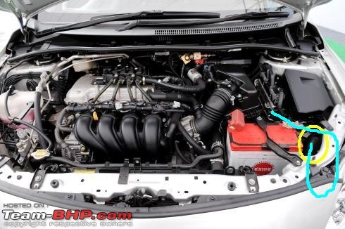
The Corolla's is even more weirder. Have a look below. There's a snorkel from where the air enters circled below in yellow, then the tube goes down into the bumper, then takes a 180 degree bend, comes back up and goes around the snorkel, around the battery and into the bottom of the air box.

If the idea is to have a shortest intake length why did toyota design a 180 degree loop. I can right now just unplug the tubes and have the loop removed by connecting the snorkel directly to the air box without the loop by routing it around the battery.

Aspects of designing an Air Intake Revision-corolla-altis-engine.jpg
Vid6639 is offline  
Old 5th December 2010, 21:46   #3
Senior - BHPian
 
gigy's Avatar
 
Join Date: Jul 2006
Location: mumbai
Posts: 1,321
Thanked: 47 Times

Aren't that loop given to pass air through a resonator box to keep intake noise minimum and also get water fly off from the primary air flow path?
Those plastic piping also doesn't heat up the air which is flowing after filter unlike the metal plumbing of KN etc....

Basically i feel now only a jet engine likes ram air intakes.

Last edited by gigy : 5th December 2010 at 21:49.
gigy is offline  
Old 6th December 2010, 14:57   #4
CPH
BHPian
 
Join Date: Jan 2010
Location: London
Posts: 579
Thanked: 35 Times

Quote:
Originally Posted by vid6639 View Post
CPH that's a very informative post.

After reading your post I went down to the garage and spent some time looking at the air intake design for both my cars.

The Figo TDCi plumbing was a complete mystery to me. It starts from the left fender somewhere inside then goes to the air filter a good 3-4 foot long pipe and there's another shorter one from the turbo.

The Corolla's is even more weirder. Have a look below. There's a snorkel from where the air enters circled below in yellow, then the tube goes down into the bumper, then takes a 180 degree bend, comes back up and goes around the snorkel, around the battery and into the bottom of the air box.

If the idea is to have a shortest intake length why did toyota design a 180 degree loop. I can right now just unplug the tubes and have the loop removed by connecting the snorkel directly to the air box without the loop by routing it around the battery.

Attachment 464482
The Figo TD intake is technically wrong and even worse executed. It difinitively should be much shorter and different.

The Altis design shows that the Toyota engineers had some torque issues, which is why they added length on to the intake, But again this is poorly executed. In performance tuning 180 degree bends are a no-no.

It might not have expressed myself clearly. My apologies for it. On the normally aspirated engines length is needed for torque gains and some power gains too. This is the crucial differenc e between normally aspirated intakes and turbo intakes. The turbo intakes should be short.
CPH is offline  
Old 6th December 2010, 15:57   #5
BHPian
 
kaustubh_vaze's Avatar
 
Join Date: Jul 2006
Location: Pune
Posts: 224
Thanked: 53 Times

Hey CPH,
In the Palio 1.6, we can see the air intake take a complete U turn just before the intake manifold. I think that is not good for the car. Routing it straighter to the left side of the car makes more sense I guess. Your thoughts?
Attached Thumbnails
Aspects of designing an Air Intake Revision-palio-1.6-engine-bay.jpg  

kaustubh_vaze is offline  
Old 6th December 2010, 18:01   #6
Senior - BHPian
 
pranavt's Avatar
 
Join Date: May 2008
Location: Mumbai
Posts: 1,682
Thanked: 641 Times

Quote:
Originally Posted by kaustubh_vaze View Post
Hey CPH,
In the Palio 1.6, we can see the air intake take a complete U turn just before the intake manifold. I think that is not good for the car. Routing it straighter to the left side of the car makes more sense I guess. Your thoughts?
Looks like space was an issue.

@CPH: Thanks for creating this topic. Should be fun to break misconceptions. Perhaps the mods should change the title to "Art of designing an Air Intake Revision". People waste too much time thinking of how to get the exhaust out of the system but focus less on how to get air into the engine in the first place Designing a good intake is an art in itself.
Last edited by pranavt : 6th December 2010 at 18:03.
pranavt is offline  
Old 6th December 2010, 18:17   #7
Senior - BHPian
 
gigy's Avatar
 
Join Date: Jul 2006
Location: mumbai
Posts: 1,321
Thanked: 47 Times

Amazing why all this manufacturers didn't know such basic performance enhancing techniques. how many bhp have been lost in turning the airflow? may be the restriction is to improve the mileage in here

If you can manage to increase the partial pressure of oxygen in the total volume of air going into the combustion chamber then it will give you more output, rest all is..

turbocharging is one way, for the rest of the cars engine sucks quite good.

Last edited by gigy : 6th December 2010 at 18:35.
gigy is offline  
Old 7th December 2010, 02:49   #8
CPH
BHPian
 
Join Date: Jan 2010
Location: London
Posts: 579
Thanked: 35 Times

Quote:
Originally Posted by gigy View Post
Amazing why all this manufacturers didn't know such basic performance enhancing techniques. how many bhp have been lost in turning the airflow? may be the restriction is to improve the mileage in here

If you can manage to increase the partial pressure of oxygen in the total volume of air going into the combustion chamber then it will give you more output, rest all is..

turbocharging is one way, for the rest of the cars engine sucks quite good.

It is not that the engineers in the manufacturer's design departments would not know. It is the usless bean counters that force the cheapest possible measures onto the designers. Ben counters don't care about the environment, resources or cost for the customer after the sale is done. It is very frustrating to work with them lot and we engineers hate the guts of bean counters.
CPH is offline  
Old 7th December 2010, 07:48   #9
BHPian
 
motorpsycho's Avatar
 
Join Date: Jul 2009
Location: Hubli
Posts: 482
Thanked: 448 Times

CPH , Thanks for putting up the article, very informative.

A little doubt,

Would there be a change in the way the air flows in the engine bay when the car is in motion. A place may appear cooler , but hotter air might be directed to the spot due to the air flow. Would a thermal camera may help in getting a perfect spot.

Also is there a possibility of air starvation in the engine bay due to the air flow when the car is in motion, or is the magnitude of the engine suction always way greater then that generated by the air flow?

Thanks
motorpsycho is offline  
Old 7th December 2010, 08:28   #10
CPH
BHPian
 
Join Date: Jan 2010
Location: London
Posts: 579
Thanked: 35 Times

Quote:
Originally Posted by motorpsycho View Post

Would there be a change in the way the air flows in the engine bay when the car is in motion. A place may appear cooler , but hotter air might be directed to the spot due to the air flow. Would a thermal camera may help in getting a perfect spot.

Also is there a possibility of air starvation in the engine bay due to the air flow when the car is in motion, or is the magnitude of the engine suction always way greater then that generated by the air flow?

Thanks
Every engine bay is different. And therefore in every engine you will have different turbulence spots. Additionally you have to put in consideration the shape of the frontal area as well us the under side.

Depending on where the filter/snorkel sits you might get with increasing speed experience decreasing airpressure or turbulencen build up. In other areas the air remains rather still and in some areas you will see an increasde of pressure. finding the right spot is not easy.

When the engine sucks in air it accelerates air standing virtually still behind the valve. This takes energy away that can't be utilised on the frank shaft. Additionally when the suction starts (valve open) the pressure in the port behinde the valve drops. The more the turbulence factors hit the entire intake the more time is getting lost in getting the optimal amount of air in the combustion chamber. The result is that the intake loses you potential power. A poorly designed air intake will lose potential power.

This is only one aspect to look at. If you have additional turbulences around the filter mouth or snorkel, which in effect is an extension of the air intake you will see further losses with increasing speed. This is irrespective whether you have a turbo or a normally aspirated application.

The only reason why we designers of air intake revisions are able to gain against the OE intakes is the fact that we are boringly pedantic in our approach eliminating all turbulence possible and look for the right pressure environment with air that has got the lowest possibly temperature.
CPH is offline  
Old 7th December 2010, 09:14   #11
Senior - BHPian
 
Join Date: May 2005
Location: Location
Posts: 5,766
Thanked: 9,057 Times

CPH, which of these four enclosed conical filter is the best in your opinion - Green Storm, K&N Apollo, BMC CDA, BMC DIA? I know that the performance of the air intake system depends a lot on the way it is designed and routed, but here i'm only like to know which enclosed filter is the best.

Reason is i would like to know if there is a real advantage if paying more for a particular brand. In that list BMC CDA is the most expensive here followed by DIA and others. And while others use a regular flow pattern - air flows over the filter and then into it, BMC uses a reverse flow where the ar flows into the filter and then out. Is there an advantage in this type of flow?

I'd like to go for a performance air intake for my AStar, but no one makes a dedicated kit for this car and so trying to find out which is the best of this lot.
Sankar is offline  
Old 7th December 2010, 10:55   #12
CPH
BHPian
 
Join Date: Jan 2010
Location: London
Posts: 579
Thanked: 35 Times

Quote:
Originally Posted by Sankar View Post
CPH, which of these four enclosed conical filter is the best in your opinion - Green Storm, K&N Apollo, BMC CDA, BMC DIA? I know that the performance of the air intake system depends a lot on the way it is designed and routed, but here i'm only like to know which enclosed filter is the best.

Reason is i would like to know if there is a real advantage if paying more for a particular brand. In that list BMC CDA is the most expensive here followed by DIA and others. And while others use a regular flow pattern - air flows over the filter and then into it, BMC uses a reverse flow where the ar flows into the filter and then out. Is there an advantage in this type of flow?

I'd like to go for a performance air intake for my AStar, but no one makes a dedicated kit for this car and so trying to find out which is the best of this lot.
A Star is on my development list when I come over.

Piperx (all). Apollo, 57i and Storm are a waste of time. The CDA is not bad, but needs re-working for best results. DIA is better choice. However I would not go for enclosed element. I would go wherever possible with an open twin cone. The best flowing twin cone, which is the best flowing filter at the moment is a Taiwanese one, which is a fraction of the cost of all other filters.

One big problem with enclosed elements is the feed to the filter. The pipe supplied with the BMC, K&N Apollo, Piperx Viper is an insult. A much better pipe is needed and it is important to have a good flowing mouth piece located in the right place.
CPH is offline  
Old 7th December 2010, 11:43   #13
BHPian
 
motorpsycho's Avatar
 
Join Date: Jul 2009
Location: Hubli
Posts: 482
Thanked: 448 Times

Quote:
Originally Posted by CPH View Post
Every engine bay is different...

........possibly temperature.
Thanks for the detailed clarification CPH. I Always used to wonder this whenever I opened the airbox of my motorcycle. I knew they may have done some amount of CFD analysis of the air box. But then again it finally comes down to the space in the engine bay!!

Thanks again!!
motorpsycho is offline  
Old 7th December 2010, 12:12   #14
Senior - BHPian
 
Join Date: May 2005
Location: Location
Posts: 5,766
Thanked: 9,057 Times

Quote:
Originally Posted by CPH View Post
A Star is on my development list when I come over.

Piperx (all). Apollo, 57i and Storm are a waste of time. The CDA is not bad, but needs re-working for best results. DIA is better choice. However I would not go for enclosed element. I would go wherever possible with an open twin cone. The best flowing twin cone, which is the best flowing filter at the moment is a Taiwanese one, which is a fraction of the cost of all other filters.

One big problem with enclosed elements is the feed to the filter. The pipe supplied with the BMC, K&N Apollo, Piperx Viper is an insult. A much better pipe is needed and it is important to have a good flowing mouth piece located in the right place.
Thanks for the info CPH, it helped. Its the DIA which i was leaning towards since its less expensive than the CDA, and its great to know that DIA is even better than CDA!

Would a pipe with a funnel shaped entry make a better alternative than the stock pipe supplied with these kits? Apollo has a funnel shaped entry point for its pipe.

Hoping that you do come out with a nice AIR for AStar soon.

Maruti they themselves revised the airbox design of the AStar this year. New AStars come with a better (i think since the air intake snorkel is placed facing forward in the bumper) airbox design, in my car the box sits on top of the engine and there is a pipe which going to the right side of the engine and it sucks air from inside the engine compartment. I'm sure that this is absorbing a lot of radiant heat!!
Sankar is offline  
Old 7th December 2010, 13:47   #15
Team-BHP Support
 
Vid6639's Avatar
 
Join Date: Jul 2006
Location: Bangalore
Posts: 17,730
Thanked: 43,486 Times

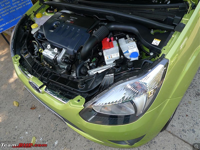
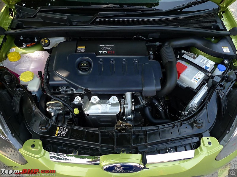
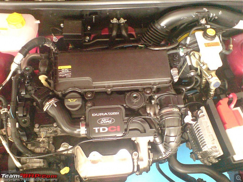
How does the Fiesta/Figo TDCi intake work? I see some pipe running from turbo, one from the left fender.

Aspects of designing an Air Intake Revision-tdci.jpeg

edit: pics of the ikon TDCi above and Figo below.

Aspects of designing an Air Intake Revision-ford_figo_02.jpg
Aspects of designing an Air Intake Revision-ford_figo_01.jpg

Last edited by Vid6639 : 7th December 2010 at 14:01.
Vid6639 is offline  
Reply

Most Viewed


Copyright ©2000 - 2024, Team-BHP.com
Proudly powered by E2E Networks