| Re: Aspects of designing an Air Intake Revision
Thank you CPH. I appreciate the gesture & the effort. Quote:
Originally Posted by CPH  I follow khoj's request |
I am posting below photographs of a Cosworth CAI installed in my Swift with the 1.3 L petrol engine. The kit is manufactured by Cosworth specifically for the Swift (per Cosworth India) and was installed by Cosworth's own engineer at their India HO in Pune. 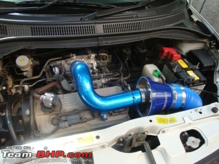
I have also quoted your first post where the areas of concern wrt to the kit installed in my car have been reproduced in bold. If you could let me have your observations/comments/suggestions on the installed kit wrt to the same and otherwise, it would be of great help. 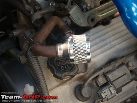
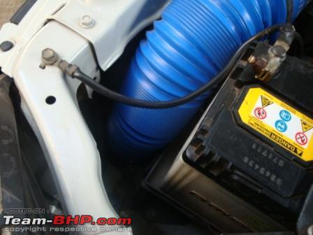
This kit comes along with a breather valve. Per the Cosworth engineer this is a two way valve and helps maintain a certain volume of air at a certain pressure in the cylinder head by either breathing in or out as the requirement might be. As to the 'certain' values the reply was it is per design and they are specific to the Swift's 1.3 L engine as the kit is designed for the same. Quote:
Originally Posted by CPH The objective of the performance oriented designer of an AIR is to get as much air into the engine at any given rpm as well as any given speed. Sounds logical. Sounds simple.
It would be simple if we wouldn't have to deal with the laws of flow dynamics. Flow dynamics is as much a blessing as it is a curse.
To start with we have to look at 2 scenarios, which have distinctive design differences.
1. Normally aspirated AIRs
2. Force induced AIRs |
Unless the latter is just another fancy name for Turbo charged, which one is this? Quote:
Originally Posted by CPH Next point to figure is where do we have the lowest amount of heat drawn in. Finding such a space is not always difficult. But having fouind that position for the intake we have to deal with more problems. If the car is stationary a smooth intake might work best. this can change dramatically when the car is moving due to turbulences increasing with speed because of the chassis and engine bay design. This can have as much of an input whether the air drawn from in side the engine bay or with a closed system with a snorkel coming in from the front. A CAI in many cases does not work as they are not professionally placed.
| 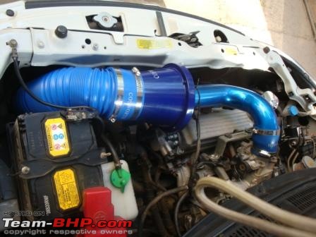
How is the placement in this case? I did enquire and was advised that there was no heat shield available. I am wondering whether heat rising from the cylinder head can be conducted on to the air intake pipe running over it. Should this be a concern in our local ambient conditions. Quote:
Originally Posted by CPH The above mentioned problems we find in normally aspirated AIRs too. The only difference is the design of the pipe before the throttle body. What wee are aiming to get the best results is a combination of gas speed and inertia. The gasspeed is dependent on the rpm.
The higher the gas speed the better it is throughout the rpm range. But physics hits us there. To maintain a certain speed, we need to make the diameters accordingly. If we are goiong to small we have good torque but lose high end. If we go too big we gain peak power but will loose bottom end torque. We can use some tricks to overcome rthis partly, but theses tricks have their limitations too. | 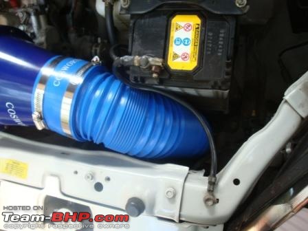
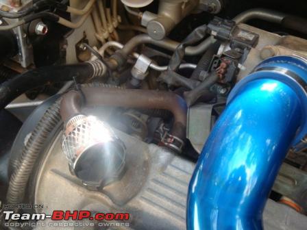
Two views of the air intake pipe. Though it is not clear but the mouth of pipe is just behind the radiator fan. 
The pipe can be elongated further and the bend radius can be increased if need be. 
Is the pipe diameter sufficient. It is about 4" for the initial run of the PVC tube and reduces to around 2.5" after the conical filter, I did not measure just quoting by visual reference. Quote:
Originally Posted by CPH Bends should be kept as a minimum and when needed the best results are achieved if the bend is about 10 degrees overbent and then corrected back by the 10 degrees. | 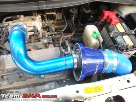
Is the bend radius sufficient? Quote:
Originally Posted by CPH CAIs need a lot of research and engineering to work and can't just be linked to the front at will when advantages are to be expected. The often disturb the rather still air badly when the car is moving, which is bad news. |
I can only hope that coming from Cosworth the kit is an outcome of proper research. I was quite hesitant of installing the same but the Cosworth name drew me in.
Overall I have observed some increase in initial response from the engine at low RPMs. The car now pulls cleaner and quicker from standing starts as also roll ons in second gear from crawling speeds at say 1200 ~ 1300 RPM have definitely improved. I cannot comment on improvements in top speeds as on my Bombay Delhi run in this car I restricted the top speed at 110 Kmph. there is no change in the fuel consumption after kit installation it remains steady at 12 Kmpl with 100% air con. On the highway run the mileage was 14 Kmpl after the install, this is the same as my numerous runs on Bom - Pune Xpressway and Nasik / Goa highways prior to the install. Again top speeds were restricted at 110kmph on the Xpressway and 80~90 kmph on the other highways.
A fellow member had put forth an interesting point regarding these CAIs. Per his view the large diameter of the intake pipe would allow more dust etc to be carried into the filter resulting in either these filters becoming choked thereby impeding air intake or in others it would allow fine granules to pass through the filter on account of the increased air flow speed and the high volume being sucked in and thereby damaging the engine. This has kept me from installing a direct bolt on kit made specifically by 'PiperCross' for the Cedia on mine. Let me have your views on the above. BTW the Cosworth filter does not need any oil etc for cleaning. I was advised to take it off maybe once in a couple of years and to blow air in from the opposite end using an ordinary vacuum cleaner running in reverse or even a hair dryer blower without the heat on.
Last edited by khoj : 14th December 2010 at 00:21.
| 

 13th December 2010, 20:32