This is the DIY for fitting a Race Chip to your Optra (similar procedure for other cars as well).
To get more details regarding the Race Chip, visit their
site and check
this thread.
You need to order specifically as per your car. The Race Chip remains same, but the connectors vary.
Once you receive your Race Chip and unbox it, these are the contents :
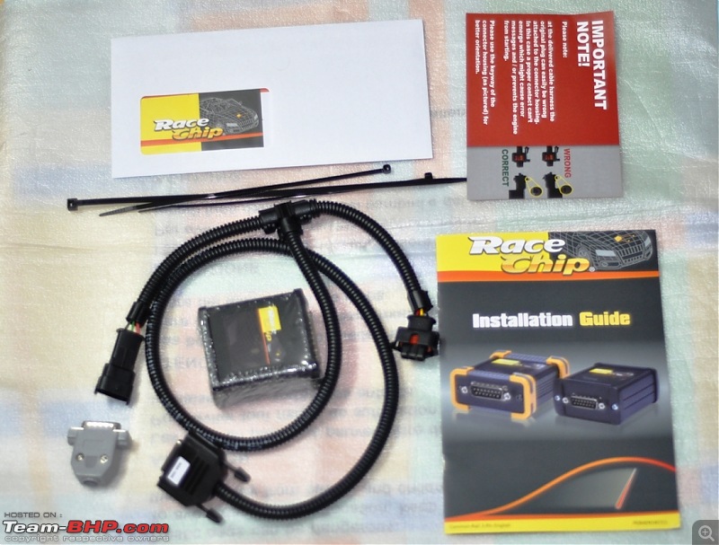
1. Race Chip
2. Common Rail T-Connector (specific to your car)
3. Check Plug
4. Cable Ties
5. Generic Instruction Manual
6. Leaflet specific to your car's rail connector
7. Receipt and Warranty
Tools required :
1. Socket wrench (to open the engine cover)
Many cars have engine covers that can be just pulled out.
No tools required in that case!
Level of complexity :
Dummy friendly. (You really have to be hell bent on making a mistake to get this wrong). It's very easy to do and someone with no DIY experience can do it easily.
Time taken :
15 minutes (from bonnet open to close), although you may go as per your own pace.
Procedure :
1. Switch off the ignition of the car, remove the key out. Pop open the bonnet of the car and then close all doors before you start the assembly
so that there is no residual current flowing.
(
If you are not sure how to do this, well, do not proceed - call your trusted mechanic and show him the rest of this post - tell him to follow these instructions !)
2-a. It is a good idea to disconnect the
positive terminal of the battery for now. This provides safety, and at the same time also resets the dynamic memory of your ECU.
You may skip this step and proceed ahead
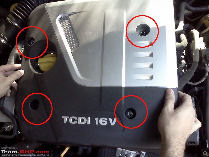
2-b. You will see a cover over the engine block. In this car, you need to open the 4 nuts/bolts (marked in red) and remove the cover. This varies from car to car and in some cars, it is a simple pull-out type.
3. What you see is the engine block. In this you need to locate the position of the
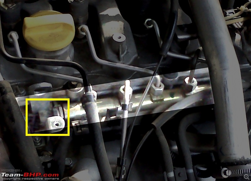
Common Rail (The thing that CRDi, CRDe, DiCOR etc take their name from). The Common Rail is a
solid looking metal pipe characterized by
3-4 (or more depending on the number of cylinders)
steel pipes coming out of it from nuts and going in towards the engine cylinders.
See the pics below for the whole view and the highlighted view of the rail.


The rail has a
wire and connector going into it at one end (marked in yellow). In this car, this connector is a 3 pin connector +12V, Rail Signal, Ground. This is a male connector (has a protrusion).
(You may argue here based on the way the pins are exposed as to which is male and which is female, but here, lets assume it as I say -
male is the protruding one, female is the receptor)
Here is a closer shot of the rail.

4. You need to grab a hold of the connector, release the locking clip by pressing it and gently ease out the connector.
The connector with the clip to be pressed

The connector removed

5. Now take the T-connector cable out of the Race Chip box and
plug in the male signal connector (removed in step 4)
into the female connector of the T-connector cable 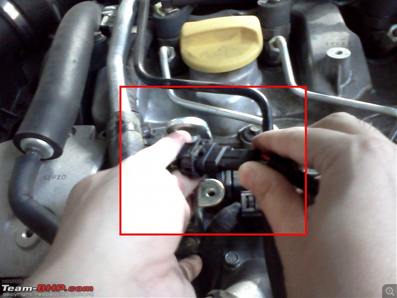
6.To complete the circuit,
plug in the male connector of the T-Connector cable into the female socket of the Common Rail (the socket from which you removed the connector in step 4)

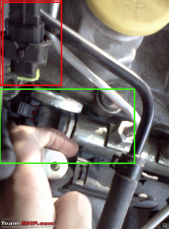
7-a. Now, if you had disconnected the +ve battery terminal in step 2a, connect it back.
7-b. Now, plug in the Check Plug into the serial connector of the T-Connector cable. Switch on the ignition (do not crank it). If everything is done correctly, the indicator LED in the check plug will glow.
If the LED does not glow, check the connections all over again to see that you have not put them in reverse or forced them in the wrong way.
If the LED still does not light up, remove the entire thing, restore the connections back to stock condition and write to the RaceChip team. Do not start your vehicle if the LED does not glow. 
See the connector placement above.
8. If everything works out fine, remove the plug. Route the cable in a convenient manner (see 2nd pic), keeping it away from movable parts, heat sources etc. Then connect the Race Chip to the serial connector and tuck it neatly into place where it will stay away from heat. Use the cable ties to bind the connector harness and the Race Chip in place.
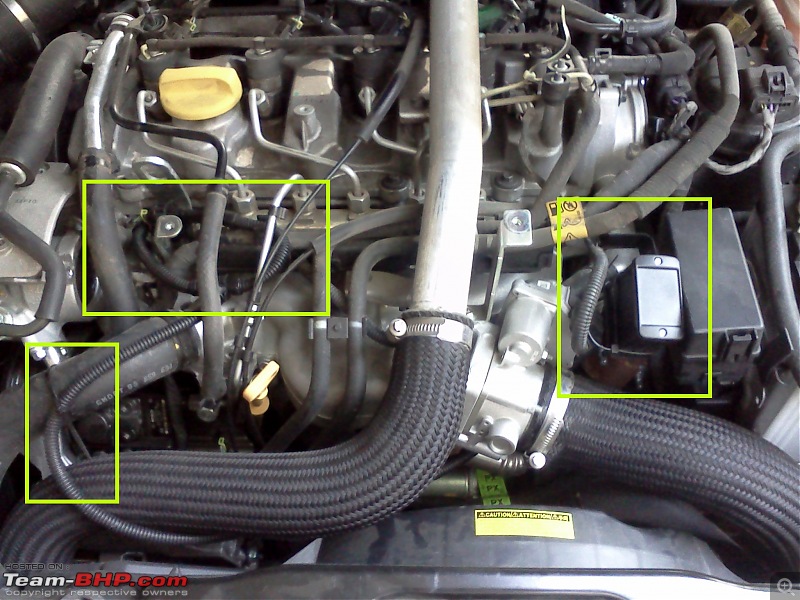

Note the way I have kept the flat end of the Race Chip accessible. That is so that I can easily open the cover (by opening the 2 screws) and make the necessary changes / adjustments to the 2 dials.

 (1)
Thanks
 (1)
Thanks
 (6)
Thanks
 (1)
Thanks


 ) - haven't heard of or faced any issues with the low beam.


 ). I was done in 15 minutes, and was washing my hands when the guys arrived.