Team-BHP > In-Car Entertainment
Register New Topics New Posts Top Thanked Team-BHP FAQ


Closed Thread
  Search this Thread
18,088 views
Old 2nd May 2006, 18:06   #1
Senior - BHPian
 
gunbir's Avatar
 
Join Date: Sep 2005
Location: New Delhi
Posts: 2,465
Thanked: 32 Times
How to determine what size Power Cables for ICE? Answers inside...

Folks, There have been a lot of questions around here lately on this subject so please refer this table when designing the cabling for your ICE system.


People please post your 'power' related queries in this thread...
gunbir is offline  
Old 2nd May 2006, 23:19   #2
Senior - BHPian
 
Join Date: Mar 2006
Location: Faridabad
Posts: 6,815
Thanked: 305 Times

For the current rating of a amp one could see the fuse on the amp, simply add the sum of all the fuses on the amp for the current rating. for eg in alpine MRD-1005 there are four fuses of 20 amps each so it sums to 80 amps.


Now that my amp is rated at 80 amps now I have check the length of the wire I am going to use. Suppose U r going to use a 4 mtr length then a 4 awg wire is sufficent for the purpose.

low_bass_makker is offline  
Old 3rd May 2006, 00:34   #3
Senior - BHPian
 
gunbir's Avatar
 
Join Date: Sep 2005
Location: New Delhi
Posts: 2,465
Thanked: 32 Times

Quote:
Originally Posted by low_bass_makker
For the current rating of a amp one could see the fuse on the amp, simply add the sum of all the fuses on the amp for the current rating. for eg in alpine MRD-1005 there are four fuses of 20 amps each so it sums to 80 amps. Now that my amp is rated at 80 amps now I have check the length of the wire I am going to use. Suppose U r going to use a 4 mtr length then a 4 awg wire is sufficent for the purpose.
LBM thanks... but you are completely WRONG. Fuse rating does NOT equal max current draw. I think you need to read up on fuses and how they work.

For your Alpine MRD-M1005 to output 1000w at 12v with only 80A consumtion it would have to be near 100% efficient. Which is nowhere near possible even for a Class D amp. at high SPL levels and with the bass boosts and EQ you use, your amps should consume over 120A each.

So... yet again... and once and for all... YOU NEED 2ga Cable. I dont know what its gonna take to get this though to you...

Last edited by gunbir : 3rd May 2006 at 00:36.
gunbir is offline  
Old 3rd May 2006, 01:45   #4
Senior - BHPian
 
Join Date: Mar 2006
Location: Faridabad
Posts: 6,815
Thanked: 305 Times

Quote:
Originally Posted by gunbir
LBM thanks... but you are completely WRONG. Fuse rating does NOT equal max current draw. I think you need to read up on fuses and how they work.

For your Alpine MRD-M1005 to output 1000w at 12v with only 80A consumtion it would have to be near 100% efficient. Which is nowhere near possible even for a Class D amp. at high SPL levels and with the bass boosts and EQ you use, your amps should consume over 120A each.

So... yet again... and once and for all... YOU NEED 2ga Cable. I dont know what its gonna take to get this though to you...
Sir Gun-bir dont get I was not talk about my install It was about your post for other people to share knowledge with people but as u have raised the topic I will clearify the doubts u have.


Firstly ->
http://www.crutchfield.com/S-odhJbM6...500MRDM105#Tab

from this above link U can see that the site recommends
Quote:
» 4-gauge power and ground leads and 80 amp fuse recommended — wiring and hardware not included with amplifier
Secondly ->
http://www.crutchfield.com/S-odhJbM6...500MRDM105#Tab

Quote:
V12 AccuClass-D Mono Amplifier: The V12 AccuClass-D amplifier design delivers massive power without correspondingly huge current draw. This amplifier's true digital design keeps the signal purer and makes the amp extremely efficient (approximately 80%). V12 AccuClass-D amps use digital signal processing to adjust input gain, crossover point, and Bass EQ, all controlled using the Alpine Digital Control Center located under the top-mounted access panel.
http://www.alpine-usa.com/en/product...&lang=en&tab=F

Quote:
CEA-2006 Power Rating
CEA-2006 Power Rating (40hm@14.4V = 1%THD+N), S/N 80dBA (Ref. 1W into 4Ohm): 700W x 1

RMS Power (at 12V,20Hz-200Hz)
Per channel into 2 ohms : 700W x 1
Per channel into 4 ohms : 500W x 1

RMS Power (at 14.4V,20Hz-200Hz)
Per channel into 2 ohms : 1000W x 1 (1% THD)
so from the formula u just given above in the post we can calulate the power requirements of the amp.

at 14.4 volts and 2 ohms the amp makes 1000 watts rms, as the amp is 80 % efficient we can drive to the result thats is

(1000 x 100/80) / 14.4 = 86 amps

that is nearly close to 80 amps.

but again we can calcuate for 12 volts and 2 ohms the amp makes 700 watts rms, as the amp is 80 % efficient we can drive to the result thats is

(700 x 100/80) / 12 = 73 amps

which is also near to 80 amps , Also when we play system to its full capacity a little voltage drop is there so the 14.4 will come near to 12 volts. so the average rate could be calulated as 80 amps.


Also I have removed all the bass warrior from my car

So I again ask u to please explain to me that how did u derived to 120 amps figure as I cannot understand. So acoording to my last post I think my calculation are correct for a 4 gauge is correct for my amps.

correct me If I am wrong at some place
low_bass_makker is offline  
Old 3rd May 2006, 09:15   #5
Senior - BHPian
 
gunbir's Avatar
 
Join Date: Sep 2005
Location: New Delhi
Posts: 2,465
Thanked: 32 Times

Quote:
Originally Posted by low_bass_makker
at 14.4 volts and 2 ohms the amp makes 1000 watts rms, as the amp is 80 % efficient we can drive to the result thats is

(1000 x 100/80) / 14.4 = 86 amps

that is nearly close to 80 amps.
My dear friend. When something is called approximately 80% efficient, for calculation purpose (keeping on the safe side) I would consider it to be 76%. Now it may be 77% or 78% or 79% but I would like to play it safe. Most mainstream manufacturers tend to misquote this for marketing.

So Your formula of "(1000 x 100/80) / 14.4 = 86 amps" is a bit optimistic. Try (1000x100/76)/12v = 110A. In your case, your amp would have to consume close to 1316w @ 76% efficiency to be able to put out 1000w. Even at 80% it should consume 1250w. So based on the realistic efficiency of 76% 1316w/12v = 110A. Even 1250w/13v = 96A. Anyways you look at it, each amp pulls OVER 80A. Which clearly makes it a 2ga contender.

For all practical purpose and real life scenarios, 14.4v is rarely achieved in your car when the system is playing. Please keep a margin for error and try to 'overbuild' your system rather than 'barely there'. While 'barely there' will suffice for most small systems, for a high-watt system like yours (1300w+1300w+600w consumption) you need well over 4ga.

I would really recommend you a 1/0ga cable from your battery down to a multi-way distribution block somewhere in the boot, after which you could have short lengths of 4ga cable to your amps with separate fuses for each ourput.
gunbir is offline  
Old 3rd May 2006, 10:00   #6
Team-BHP Support
 
navin's Avatar
 
Join Date: Mar 2004
Location: Mumbai
Posts: 25,196
Thanked: 9,292 Times

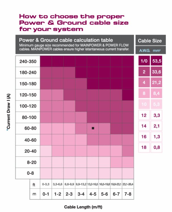
1300+1300+600 = 3200 / 0.8 = 4000 / 12 = 333A => 1/0 GA wire.

Rudra sent me a PM this morning that I am reproducing here...

the link at sounddomain given below does not open sometimes so I am repducing the contents tomake it easier for members on this forum...
http://forum.sounddomain.com/ubb/ult...c;f=5;t=007801


As many of you know, upgrading the "Big 3" wires in your engine compartment can lower the overall resistance of your entire electrical system. The effects of the lower resistance are typically:
1) Reduced dimming and smaller voltage drops
2) More stable voltage and better current flow
3) Less strain on your vehicle's charging system
So for those of you looking for a cheap and easy way to upgrade your system and help out your electrical system without adding a high output alternator or an aftermarket battery, this is the modification for you. If you have heavy dimming or are getting large voltage drops during loud bass hits, but you don't have the money to spend on a high output alternator or a battery, upgrading your vehicle's "Big 3" will usually help to reduce and sometimes even eliminate the problems. So without further ado, the "Big 3" wires are:
1) Battery negative to chassis
2) Alternator to battery positive
3) Chassis to engine
Now, I suppose it would help if I explained what each of these wires does, and to do that I would like to paraphrase an explanation by IMTfox from a while ago: Think of your vehicle's charging system as two different circuits, one consisting of your amplifier and your battery, and the other consisting of your alternator and your battery. The current in your electrical system flows from your positive battery terminal to your amp, from your amp's ground to the chassis, and then from the chassis back to the negative battery terminal. But how does it get to the positive terminal in the first place? That's where the alternator comes in. Current in the second circuit flows from your alternator's positive post to the battery's positive terminal, then from the battery's negative terminal to the chassis, and from the chassis back to the block, which happens to be the grounding point for your alternator.
So, from your battery, you have the power wire going to the power terminal on your amplifier and then your amplifier is grounded to the chassis of the vehicle. From here the current needs a way to get back to the negative battery terminal, and that way is through the first of the "Big 3," the battery negative to chassis wire. Upgrading this wire will "upgrade" the circuit between your battery and your amp by giving the current a larger path to flow through to get back to the battery.
Now, think of your alternator as the battery and your battery as the amp. From the positive post on your alternator, you have the second of the "Big 3," the alternator to battery positive wire supplying "power" to your battery. From there the battery, just like your amp, is grounded to the chassis through the wire mentioned in the previous paragraph. Again, the current needs a way to get from the chassis back to the alternator's "negative terminal" and that way is through the last of the "Big 3," the chassis to engine wire. Since your alternator is most likely mounted to your engine block using a metal or conductive mounting bracket, you can simply add your new wire from the chassis to one of the mounting posts for the alternator. Upgrading these two wires will "upgrade" the circuit between your alternator and your battery, again giving the current a larger path to flow through.
----------------------------------------------
Now that you understand exactly what the "Big 3" do, it's time to upgrade them to a larger gauge wire. You can use regular power wire from installing your car audio equipment, ring terminals, and crimping equipment just the same as you would for any other install. Let's start with the first of the "Big 3," the battery negative to chassis wire:
1) Disconnect your battery's negative terminal and get the stock wiring out of the way. You might have to cut it and crimp a new ring terminal onto it. I found it helpful to use aftermarket battery terminals with multiple ports on them also.
2) Scrape away the paint and drill the hole for your connection of the larger wire, or connect it to the stock grounding point. Either way you do it, make sure it is bare chassis metal, not covered by paint, and that the connection is as tight and secure as possible:


3) Secure the new wire to the chassis and reconnect the vehicle's stock chassis ground, but DON'T reconnect the vehicle's negative battery terminal yet! You may find it helpful to cover the negative battery terminal with a cloth or other non-conductive material and just lay the terminal on it until you're ready to reconnect it later.
Moving on to the next of the "Big 3," let's upgrade the alternator to battery positive wire:
4) Locate the vehicle's alternator and look for a terminal post connected to it. The post shouldn't be hard to find. It should have only one wire connected to it, and it should lead to the positive terminal on the battery, possibly through the fuse box.

5) Disconnect the stock alternator to battery positive wire from the positive post and connect it to the post again with the new wire added.
6) Run the wire either through your fuse box if applicable or through a fuse. The fuse should be sized to match the max ampacity of your wire, not the output capability of your alternator. As you can see I just went through the fuse box, so my upgrade is probably not making as much of a difference as it could if it were fused externally, but my alternator is capable of withstanding the draws anyway so I'm not particularly worried about it. If I ever begin to see a problem w/ current draws, I will probably fuse the wire externally with a 300A or so fuse...
7) From the fuse, connect the wire to the positive terminal on your battery, again, leaving the stock wiring connected when you're done. The picture below shows the alternator to battery positive wire run from the alternator through my fuse box to the positive battery terminal.

Last, let's move to the chassis to engine wire: (Again, because your alternator is grounded to the block, all you need to do is find a bolt somewhere on the block and connect it to the chassis. The alternator's mounting bracket is usually a good place to find these bolts).
8) Again, either drill a new hole or connect this wire to the stock chassis ground. From the chassis ground, run the wire back to one of the mounting posts for the alternator (or to a bolt on the engine block).

9) That's it! You're done. Reconnect the vehicle's negative battery terminal and check out the difference! Below is a shot of the "Big 3" upgraded in my car. The other wire you see coming out of the battery's positive terminal is obviously my amp's power wire.

----------------------------------------------
Helpful hints:
1) Leave the stock wiring attached after you're done. Don't replace the stock wiring, add onto it. Current will take the path of least resistance anyway, so replacing the stock wire will only make more work for yourself.
2) When fusing your alternator to battery positive wire, fuse it toward the battery end of the wire. As IMTfox points out later in this thread, the battery will explode if it's overloaded, while the alternator will only burn out its regulator which won't cause much damage except to the alternator itself. Exploding batteries are no fun!
3) When crimping large gauge terminals for 1/0awg and sometimes even 4awg, a vice works well. Crimp one side of the terminal at a time, creating an overlapping edge. Put the boot around this and then wrap it in electrical tape if you want. the most secure connections will occur in this way.


4) Lastly, prepare all your materials and tools BEFORE you are ready to upgrade. Know what you are doing before you start so you can be done as quick as possible. The majority of vehicles have computers that will reset after the battery is disconnected for a long time and they can cause older vehicles to do strange things if they reset.
Hopefully this clears up most of the questions you had about why we upgrade the "Big 3" and how it helps to stop dimming and other electrical problems.

Last edited by navin : 3rd May 2006 at 10:29.
navin is offline  
Old 3rd May 2006, 10:25   #7
Senior - BHPian
 
gunbir's Avatar
 
Join Date: Sep 2005
Location: New Delhi
Posts: 2,465
Thanked: 32 Times

Quote:
Originally Posted by navin
As many of you know, upgrading the "Big 3" wires
OhmiGod... things move really fast here. I sent the link for 'The BIG 3" to KB100, who must have sent it to Rudra Sir, who sent it to you. Navinji, this article is from another Car Audio forum and I think we are violating by pasting it here... at best I think we should just link to it.
gunbir is offline  
Old 3rd May 2006, 10:27   #8
Team-BHP Support
 
navin's Avatar
 
Join Date: Mar 2004
Location: Mumbai
Posts: 25,196
Thanked: 9,292 Times

Can you give me a link I can edit my post accordingly. thanks for the info.
navin is offline  
Old 3rd May 2006, 11:13   #9
Senior - BHPian
 
Join Date: Mar 2006
Location: Faridabad
Posts: 6,815
Thanked: 305 Times

Quote:
Originally Posted by gunbir
My dear friend. When something is called approximately 80% efficient, for calculation purpose (keeping on the safe side) I would consider it to be 76%. Now it may be 77% or 78% or 79% but I would like to play it safe. Most mainstream manufacturers tend to misquote this for marketing.

So Your formula of "(1000 x 100/80) / 14.4 = 86 amps" is a bit optimistic. Try (1000x100/76)/12v = 110A. In your case, your amp would have to consume close to 1316w @ 76% efficiency to be able to put out 1000w. Even at 80% it should consume 1250w. So based on the realistic efficiency of 76% 1316w/12v = 110A. Even 1250w/13v = 96A. Anyways you look at it, each amp pulls OVER 80A. Which clearly makes it a 2ga contender.

For all practical purpose and real life scenarios, 14.4v is rarely achieved in your car when the system is playing. Please keep a margin for error and try to 'overbuild' your system rather than 'barely there'. While 'barely there' will suffice for most small systems, for a high-watt system like yours (1300w+1300w+600w consumption) you need well over 4ga.

I would really recommend you a 1/0ga cable from your battery down to a multi-way distribution block somewhere in the boot, after which you could have short lengths of 4ga cable to your amps with separate fuses for each ourput.
Bro I think U r be pushed of some cliff, hang on I am not doing it.

I think u dont read completely what I said earlier the site self recommends a "4 gauge wire kit with a 80 amps fuse " so according to U they are fool.

Then again acording to ur formula again I am going to calculate the amperage of mrd 1005 so that u clearly get the picture.Watch closely

(1000 x 100/76) / 14.4 = 91.3 amps
(700 x 100/76) / 12 = 76.7 amps

Quote:
Originally Posted by gunbir
(1000x100/76)/12v = 110A
the above statments u quoted is wrong because at 12 volts the amp makes 700 watts not 1000 watts.

Also some of the experts of this forum calculated the load of this amp as

http://www.team-bhp.com/forum/186755-post19.html
http://www.team-bhp.com/forum/186768-post20.html
http://www.team-bhp.com/forum/186843-post22.html
http://www.team-bhp.com/forum/187287-post24.html

from the above link U can see the calculation done by the other knowledgable people on this thread. they have also quoted the rating close to 80 amps (Correct them all also)


Also I think the company has put some fuses on the amp also they are 20 amps x 4 a total of 80 amps. So according to ur calculations the amp is pulling 120 amps of power. The fuse on the amp would have blown away the very first day it self.

So man I think I am correct But u can correct me if i am wrong again , Even if u have some doubts u can ask me.

Last edited by low_bass_makker : 3rd May 2006 at 11:16.
low_bass_makker is offline  
Old 3rd May 2006, 11:30   #10
Senior - BHPian
 
gunbir's Avatar
 
Join Date: Sep 2005
Location: New Delhi
Posts: 2,465
Thanked: 32 Times

Quote:
Originally Posted by low_bass_makker
Bro I think U r be pushed of some cliff, hang on I am not doing it.
You dont have to... I'm gonna jump off myself...

LBM, I give up. You have ALL the answers. Your lights dim, vour volts dip, your amps clip, your fuses blow, your fuseholders melt. You indeed know it all.

So goodbye my friend. I have to go... The cliff beckons...
gunbir is offline  
Old 3rd May 2006, 12:11   #11
Team-BHP Support
 
navin's Avatar
 
Join Date: Mar 2004
Location: Mumbai
Posts: 25,196
Thanked: 9,292 Times

Quote:
Originally Posted by low_bass_makker
http://www.team-bhp.com/forum/187287-post24.html

from the above link U can see the calculation done by the other knowledgable people on this thread. they have also quoted the rating close to 80 amps (Correct them all also).
We made those statements assuming a 100% effiicieny. And in any case I am open to correction. I am almost sure JB and B&T are too (if proven wrong).

1000W @ 2 ohms = 22A
1000W @ 12V = 83A

we did not factor in efficiency as this topic was discussing the current at different parts of the amplifier.

if you take 83A and divide it by 0.8 you get 104A. Any good engineer would factor in some tolerance so round it off to 110-120A.
navin is offline  
Old 3rd May 2006, 13:07   #12
Senior - BHPian
 
Join Date: Mar 2006
Location: Faridabad
Posts: 6,815
Thanked: 305 Times

Man u r the expert I am getting back. When I joined this forum my first thread was about HO alternater people on this forum told me to change the wiring the voltage drop will go away and what not ,but even after changing the wiring the same problem is there.

http://forum.sounddomain.com/ubb/ult...c;f=3;t=031203

in the above link the expert clearly said that the fuse was not of good quality and the plastic of the fuse holder was also of bad quality. rest people here are quite intelligent to under stand what to use or not.
low_bass_makker is offline  
Old 3rd May 2006, 16:49   #13
Senior - BHPian
 
kb100's Avatar
 
Join Date: Feb 2006
Location: Bangy Boy!
Posts: 1,555
Thanked: 21 Times

Quote:
Originally Posted by navin
Can you give me a link I can edit my post accordingly. thanks for the info.
http://forum.sounddomain.com/ubb/ult...c;f=5;t=007801..

Courtsey GUNMAN! .... Lol ... things do get around all right!!
kb100 is offline  
Old 3rd May 2006, 16:54   #14
Senior - BHPian
 
Join Date: Mar 2006
Location: Faridabad
Posts: 6,815
Thanked: 305 Times

the link is incomplete use the link below

http://forum.sounddomain.com/ubb/ult...c;f=5;t=007801

Last edited by low_bass_makker : 3rd May 2006 at 16:55.
low_bass_makker is offline  
Old 3rd May 2006, 17:51   #15
Senior - BHPian
 
kb100's Avatar
 
Join Date: Feb 2006
Location: Bangy Boy!
Posts: 1,555
Thanked: 21 Times

LBM...

try telling those folks on sound domain that its an Audison kit.... and then see their reaction.... Am sure they will immediately tell you that the quality of the plastic /fuse etc cannot be the problem... that your problem lies elsewhere..

I am no fan of Audison... Hell I am not even a customer of theirs!... but I see them being regarded very highly in most of the forums I have visited lately...Audison's are respected world over!!

Seems to me you dont like the kit - why dont you get yourself a 4G kit from any other manufacturer.. and if that runs okay you have your post!!

Last edited by kb100 : 3rd May 2006 at 17:57.
kb100 is offline  
Closed Thread

Most Viewed


Copyright ©2000 - 2024, Team-BHP.com
Proudly powered by E2E Networks