Team-BHP > Technical Stuff > DIY - Do it yourself
Register New Topics New Posts Top Thanked Team-BHP FAQ


Reply
  Search this Thread
110,141 views
Old 21st December 2008, 23:33   #61
Senior - BHPian
 
Jaguar's Avatar
 
Join Date: May 2006
Location: Bangalore
Posts: 1,208
Thanked: 2,547 Times

Inspired by the thread I have bought the LEDs (white and blue), Resistors and PCB. Have to search for the soldering iron lying somewhere

Quote:
Originally Posted by vid6639 View Post
What's the wattage on the LED's. 3.5V is the voltage but what is the current they should be getting.

The stock bulb is generally 12V/8W = 1.5A current. Based on that I plan to add the LED's solder all these on a small PCB.
One electronics shop wala told me to use 2 white LEDs with 100 ohms resistor in series or 3 blue LEDs and the 100 ohms resistor.
Jaguar is offline  
Old 22nd December 2008, 23:36   #62
Team-BHP Support
 
benbsb29's Avatar
 
Join Date: Nov 2006
Location: Brisbane
Posts: 9,969
Thanked: 13,231 Times

Quote:
Originally Posted by vid6639 View Post
What's the wattage on the LED's. 3.5V is the voltage but what is the current they should be getting.

The stock bulb is generally 12V/8W = 1.5A current. Based on that I plan to add the LED's solder all these on a small PCB.
The holder mentions the power rating for the cabin light at 10W.
I am not sure about the specific current rating for the LEDs i am using but i believe they have a rating of about 15-20mA.

Vid, what color LEDs do you plan on using?

Quote:
Originally Posted by Jaguar View Post
Inspired by the thread I have bought the LEDs (white and blue), Resistors and PCB. Have to search for the soldering iron lying somewhere
For such a simple set-up, i dont think any soldering is even required. But then since you plan on using the PCB, you could as well do it neatly.
Let us know of your progress, Ramesh.
benbsb29 is offline  
Old 17th January 2009, 18:03   #63
Senior - BHPian
 
greenhorn's Avatar
 
Join Date: Apr 2007
Location: KL-01
Posts: 7,745
Thanked: 4,402 Times

Light Emitting Diodes

should help folks thinking about trying out this.
I tried out an initial test with some LED's and twisted wire, and it doesnt look half bad . will take some pix of them in the dark and post

planning to get some more and do a proper PCB setup
greenhorn is offline  
Old 17th January 2009, 22:52   #64
Team-BHP Support
 
benbsb29's Avatar
 
Join Date: Nov 2006
Location: Brisbane
Posts: 9,969
Thanked: 13,231 Times

Greenhorn, thanks for the link.

Here is the circuit diagram of the setup which i had usd for the LED setup. The resistors used are for 3 blue LEDs in series on each parallel arm of the circuit.

Am posting this mainly as sanju.sreekumar tried the setup and got the series and parallel arrangement wrong.

Benny's first DIY : LEDs on an Ikon-copy-led_diag1.jpg

Did anyone else have any success?
benbsb29 is offline  
Old 17th January 2009, 23:34   #65
Senior - BHPian
 
greenhorn's Avatar
 
Join Date: Apr 2007
Location: KL-01
Posts: 7,745
Thanked: 4,402 Times

bought an LM317, and was thinking of a setup with a fade in effect while turning on, as well as constant voltage to ensure the brighness remains the same...
but the quick and dirty setup works just fine , so thinking about sticking with this , probably 3x3 LED's and increasing the resistors value from 56 to something higher to reduce the max current to about 20 mA or so
greenhorn is offline  
Old 18th January 2009, 00:12   #66
Senior - BHPian
 
greenhorn's Avatar
 
Join Date: Apr 2007
Location: KL-01
Posts: 7,745
Thanked: 4,402 Times

Benny's first DIY : LEDs on an Ikon-img_2765.jpg
the spot lamps alone , to get an idea about the whiteness
Benny's first DIY : LEDs on an Ikon-img_2768.jpg
with the LED's on
Benny's first DIY : LEDs on an Ikon-img_2769.jpg
the view from below
Benny's first DIY : LEDs on an Ikon-img_2770.jpg
and from the side
Benny's first DIY : LEDs on an Ikon-img_2771.jpg
with the plastic cover removed
Benny's first DIY : LEDs on an Ikon-img_2772.jpg
the wiring - i used a lot of plastic tape to reduce the chance of a short, and uset plastic tape since it was transparent - insulation tape wouldnt have looked as nice

sorry, I couldnt take any shots of the cabin ( or rather my cam couldnt), but its a lot brighter than it was with the bulb
greenhorn is offline  
Old 18th January 2009, 00:12   #67
Team-BHP Support
 
benbsb29's Avatar
 
Join Date: Nov 2006
Location: Brisbane
Posts: 9,969
Thanked: 13,231 Times

Quote:
Originally Posted by greenhorn View Post
bought an LM317, and was thinking of a setup with a fade in effect while turning on, as well as constant voltage to ensure the brighness remains the same...
but the quick and dirty setup works just fine , so thinking about sticking with this , probably 3x3 LED's and increasing the resistors value from 56 to something higher to reduce the max current to about 20 mA or so
Greenhorn, what color LEDs are you using? If you are using the white ones with three in series then use a 82ohms resistor, and if blue, use a 47 ohms resistor in series with 3 LEDs.

Between, how exactly can we acheive the fading effect when the switch is turned off? I believe the Swift has such a fade-out effect. I would be quite interested in implementing something like that.

EDIT : Just saw the pics you'd put up. Good job!

Last edited by benbsb29 : 18th January 2009 at 00:14.
benbsb29 is offline  
Old 18th January 2009, 00:21   #68
Senior - BHPian
 
greenhorn's Avatar
 
Join Date: Apr 2007
Location: KL-01
Posts: 7,745
Thanked: 4,402 Times

white
according to the article, the LED's should be 3.6V ( dont have a multimeter with me now :( ) , so 3X 3.6 = 10.8, then the remaining 1.2V divided by 25mA gives 50ohm
I used 56 Ohms
but at 14.4, i guess it should be running 3x the current. but I'm not planning to use them a lot with the engine on, and either way, am planning to replace this with a PCB setup , possibly next week. Fade out would be hard. fade in is easy, but you'll need a circuit for that - it was given in the LM317's datasheet
greenhorn is offline  
Old 18th January 2009, 16:16   #69
Team-BHP Support
 
benbsb29's Avatar
 
Join Date: Nov 2006
Location: Brisbane
Posts: 9,969
Thanked: 13,231 Times
Fade-in and fade-out effect

Will adding a capacitor in parallel to the LEDs help realize the fade-in and fade-out effect? If so, what would be the capacitor rating i would require?
benbsb29 is offline  
Old 18th January 2009, 17:02   #70
BHPian
 
_abhay_'s Avatar
 
Join Date: Nov 2007
Location: mumbai
Posts: 38
Thanked: 4 Times

courtesy light or theater effect

Dimmer's Ive got some links really helpful. I havent tried those as my cr is still under warranty and dont was to mess up thing . circuits tested fine on a simulator on my pc.

Voltage regulation can be effectively and economically archived using ZENER Diode. threy are like voltage regulators

check these links let me know if they work . i'll be at lamington road the next day
CircuitDB | Dome light dimmer (with delay)
Dome Light dimmer A useful operation for the cars is delayed extinguishing internal lighting cabin of passengers after close some door car Dimmer
_abhay_ is offline  
Old 18th January 2009, 19:22   #71
Senior - BHPian
 
greenhorn's Avatar
 
Join Date: Apr 2007
Location: KL-01
Posts: 7,745
Thanked: 4,402 Times

with just a capacitor, you'll need a big value ( several thousand microfarads) if you want a fade in time of ~1s, for just one string of 3 LED's , and in addition, it will overload the circuit which turns this light on for the first second while the capacitor charges.

and to add to that , the dimmer works well only on bulbs. LED's light:voltage curve isnt very linear, so it will not glow at all, then suddenly turn on. You'll need something like PWM to get them to fade in and out correctly.( even with a simple IC controlled circuit like the one abhay posted works nicely only on bulbs )
greenhorn is offline  
Old 1st February 2009, 15:51   #72
Senior - BHPian
 
greenhorn's Avatar
 
Join Date: Apr 2007
Location: KL-01
Posts: 7,745
Thanked: 4,402 Times

benny was right. 56k aint enough. one of the LED's burnt out.
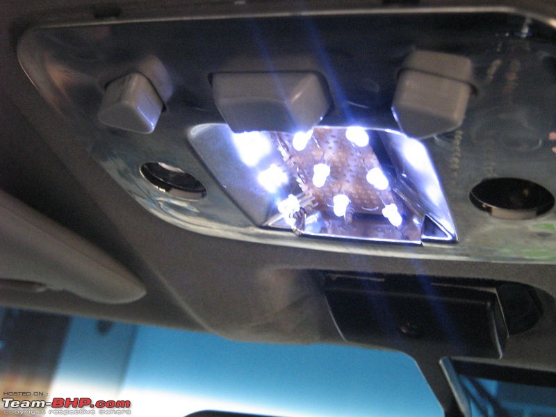
got a different colour LED this time. these look a violetish white, sort of like 10000k or more. got a Proper PCB setup made

the best part is that these LED's consume just .43W with the engine off, and 1.3W with the engine on. the bulb uses 10/14.4W correspondingly !

Benny's first DIY : LEDs on an Ikon-off.jpg

Benny's first DIY : LEDs on an Ikon-.jpg

theres more

Last edited by greenhorn : 1st February 2009 at 15:58.
greenhorn is offline  
Old 3rd February 2009, 10:20   #73
Senior - BHPian
 
greenhorn's Avatar
 
Join Date: Apr 2007
Location: KL-01
Posts: 7,745
Thanked: 4,402 Times

meh, the current ones arent bright enough. I cant find any high brightness LED's here in TVM. Will have to scout all the local shops and have a competition
greenhorn is offline  
Old 3rd February 2009, 10:40   #74
Team-BHP Support
 
benbsb29's Avatar
 
Join Date: Nov 2006
Location: Brisbane
Posts: 9,969
Thanked: 13,231 Times

Greenhorn, the PCB setup looks neat. Are these 5mm LEDs? Why dont you try the 8mm ones?
benbsb29 is offline  
Old 9th February 2009, 23:50   #75
Team-BHP Support
 
benbsb29's Avatar
 
Join Date: Nov 2006
Location: Brisbane
Posts: 9,969
Thanked: 13,231 Times

Buoyed by the success of the cabin light setup, i am now working on the bootlight. Am trying to fit in three series connections in there, but the space constraint is an issue.
benbsb29 is offline  
Reply

Most Viewed


Copyright ©2000 - 2024, Team-BHP.com
Proudly powered by E2E Networks