News
DIY: Custom instrument cluster MFD display for Skoda Laura

Owning an older generation German car is a delightful experience in a lot of ways only a petrol head can understand. However, there is a very dark side of that ownership experience which is pretty much a nightmare - unavailability of parts most of the times & ridiculous pricing if they're available at the ASC.
BHPian vsaravind007 recently shared this with other enthusiasts.
Owning an older generation German car is a delightful experience in a lot of ways only a petrol head can understand. However, there is a very dark side of that ownership experience which is pretty much a nightmare - unavailability of parts most of the times & ridiculous pricing if they're available at the ASC. This is in my opinion why most enthusiastic people change their cars as they age even though they don't want to do it whole heartedly, parts become too hard to obtain even if money isn't a problem. For most people, the time & effort is simply not worth the hassle. Reason why this DIY was attempted is because of such a reason - Super rarity of an instrument cluster LCD & the eye watering cost of replacing it at an ASC. Main reason why this DIY happened is the free time I got due to the COVID-19 triple lockdowns here in Kerala.
The Problem
There is a peculiar issue with the first batch of Skoda Laura CBU cars that came to India. Not just on Lauras, this is there in other VAG cars of the same time. The LCD MFD in the instrument cluster on the top variant, L&K goes dim on one side as the car ages. The reason for this is simple, the LCD module is actually two physical LCD modules glued together, both halves have independent electrical connectors, if the LCD driver on one side goes bad that side goes totally off or becomes less bright - This is not an issue with the backlight LEDs, LCD module itself is the issue. VAG quickly identified the problem & from next model year onwards, they revised the design & introduced an LCD panel that isn't prone to this issue. The problem started on my car about 1.5 years back, just before the COVID-19 first wave. I was able to procure a used one from a parts car for swapping it out & learnt that its not possible. It has been bugging me ever since, even though I wasn't able to use the car like I used to thanks to COVID-19, it was still bugging me every time I sit in the car, could be my OCD, but it was really bothering me every single time! Remember that the car is about 15 years old now!


Potential Solutions
There are two mainstream solutions to this issue:
1. Replace the LCD module with a new one - This is the cheapest option if it can be sourced, this type of LCD was in production for only a very short period of time, probability of getting a working used one is very less. Module is available in Aliexpress for around 6k INR, but since we cannot buy from Ali anymore, thats out of the question. Also, thinking about the cost of the unit, its pretty expensive. There is one risk to this approach, if something on the cluster board is broken, replacing the LCD won't fix it, no way to conclude the problem module without swapping out the LCD module as well.
2. Replace the cluster as a whole - This is ASC approach, it is possible to get a new cluster & swap out the old one from ASC. Unfortunately its not possible to get an old cluster from a parts car and replace it, unlike other manufacturers, VAG cars have a very complex immobilizer system and cluster is one module having immobilizer information. It is possilble to swap the EEPROM module, but the model numbers must match 1:1, the cluster on my car is not swappable with the model with the updated LCD, connectors are same, but there are a lot of differences, how do i know? I bought a used one from the same year thinking its swappable, on swapping the EEPROM, came to know that its not at all compatible - the car started without issues, but there were a bunch of dancing lights on the dash. I'm not mentioning the cost of replacing this at the ASC, just know that you can buy a used car for the same price .
My Solution
I was trying to get a replacement LCD through my FNG. Due to COVID-19, that went nowhere. During that time, I came across a video by the Humble Mechanic about an aftermarket MFD display called ColorMFA.
This gave me the idea to go by the DIY route. The ColorMFA is a cluster upgrade made by a Russian guy. It costs a lot, but it looks cool & very functional. Unfortunately, its not available or compatible with the Laura (Octavia Mk2). There was an unfinished project that I started a while back, an app for my car - The idea of the app was to control the windows, lights and a few other things through a mobile app via bluetooth. That project never got finished due to the sheer amount of time needed to decode the CAN messages. Now due to the COVID-19 lockdown, I had plenty of time in hand and decided to tackle this on my own.
Below are the requirements i've set for myself:
- It must look & feel like the OEM display
- Must have all the functionalities that I use on the original screen
- It must not drain the battery if the car isn't driven for some time
- Must show all the errors/warnings that the OEM screen shows
- It must not create any catastrophic failures - Power train CAN Bus was't tapped due to this specific reason.
- Must be easy to go back to stock if i decide to sell the car in future
- Add some additional features such as battery monitor, boost gauge & a few others
For this to workout, I needed to get the following done:
- Source an LCD display that can fit inside the cluster & easily drivable through a microcontroller
- Develop a controller board with CAN Bus interface that can communicate with the car's convenience bus.
- Decode/reverse engineer the CAN Bus data packets to get all the information I needed
- Control the powering up/down of LCD and other modules based on car unlock/lock status - This is very important as this could lead to battery drains.
The OEM LCD is slightly smaller in the cluster cavity, which is noticable if you look close enough. I had a 3.5 inch LCD screen which I bought for a different project did fit perfectly, this module can be driven by a parallel interface using a microcontroller. I started out with an STM32 microcontroller, did the CAN Bus implementation on it & all was going well. After a day or two, I killed the module by accidentally supplying 12V - I had no spares for the burnt board & COVID-19 lockdowns were in effect. That forced me go with what I had laying around - An Arduino Nano, this is a very restrictive microcontroller but was enough to get the job done. I have quite a few number of these low cost microcontrollers in my parts bin. The LCD I chose initially was really hard to program on, everything had to be doe by hand - if you want to show a text on screen that is right aligned, you've to find the character dimension of the font, multiply that by the number of characters in the text you want to display and subtract it from the width of the screen and use that value as the origin of the text! This was pretty tedious obviously & showing images was super tough, it was really hard to implement the UI on it.
Decided to hold the UI development and started concentrating on the CAN Bus decoding part of the project. This was easier this time as I attempted something similar a while back.
The Laura has 3 independent CAN Buses:
- Drivetrain CAN Bus - High speed bus that is critical, used by engine, brakes, airbag & power steering. Any errors in this bus will shut down the engine
- Convenience CAN Bus - Low speed bus, instrument cluster, door electronics, interior functions are driven by this bus
- Infotainment CAN Bus - Low speed bus, radio, amplifier, steering control etc are driven by this bus
Decided not to mess around with the drivetrain CAN bus, its a critical system & I didn't want to mess with the reliability aspect of the car. Convenience bus was the bus of choice. It can be easily accessed from behind the stereo head unit, I tapped the bus at the connector and extended the bus with a long wire routed via the glove box. Used the free software CanHacker along with an Arduino based hardware interface to intercept the CAN messages flying through the bus. Identifying and decoding messages are a really time consuming job. You've to look at messages that are changing when you do an action and decode what you want based on what you see as change on screen. Below is a screenshot of the CANHacker application sniffing the CAN Bus.

Obviously this was going to take a lot of time, luckily I'm not the first person sniffing around a VAG CAN Bus! I found a Google Sheet where someone has decoded a lot of CAN Messages of a Golf MKV GTI Convenience Bus. About 60% of CAN Bus messages were the same on both cars (thanks to VW), some required modifications to how they're interpreted though. Most of my time was spent on decoding the door open/close status. Some didn't work at all, for example the coolant temperature - it never returned the correct value.
By this time, I had a proof of concept running, I was able to get the following details from the CAN Bus:
- Odo meter reading
- Door status
- Seat belt status
- Outside temperature
- Parking brake status
- Windshield washer fluid status
- Reserve fuel / Low fuel status
- Oil level low status
- Coolant level status
- Battery voltage
- Engine RPM
- Vehicle speed
- Cluster light level knob value - This knob controls the light intensity of buttons, cluster and switches inside the cabin. This is an important feature that I use on long night drives
- Steering stalk buttons - Up/Down & OK buttons, currently these are being used for page navigation just like the OEM MFD.
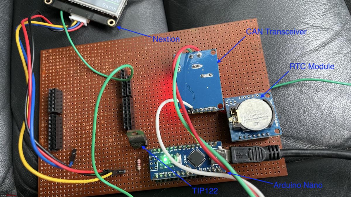
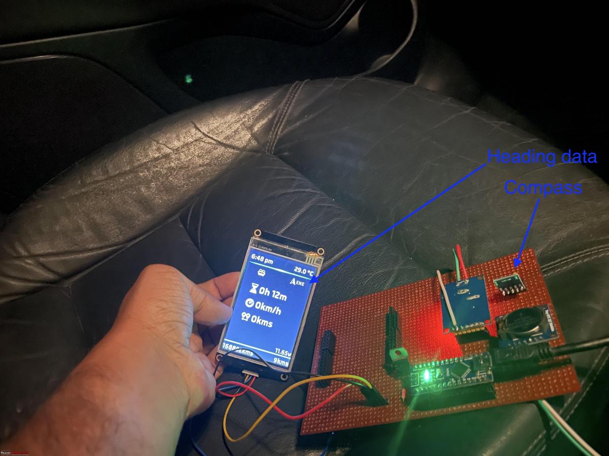
I wasn't able to decode the time from CAN Bus data correctly, hence I decided to go with a separate module for time keeping. As an additional feature, I've added a digital compass module to my system which will show a compass on the MFD. I used a TIP122 darlington transistor to control the power to modules - this is important because if the modules are kept ON, they'll drain the battery within a few days, especially the LCD needed to be turned off when the car is not in use. For trip data, I'm using the EEPROM thats part of the RTC module.
By this time, I came to the conclusion that the LCD module that I'm using isn't going to cut it, it was too much work & the results were not that impressive - too much flickering and screen tearing on changing values. I had a Nextion Enhanced HMI module in my parts bin - This was again part of an unfinished project, I bought this module to build an LiFePO4 powerwall for my house, plan was to use the Nextion module as the interface to the powerwall. It never got finished (never actually started to be honest) because of reasons, but it did help me here! Developing UI on a Nextion HMI is easy, we can use Photoshop or any other drawing tool to create graphics & use Nextion provided controls such as buttons/text to render whatever we want. It also has a scripting language in place that can be used to write logic within pages. The main advantage of Nextion is that, graphics rendering work is offloaded from the microcontroller, it uses a simple serial interface to change values on screen and for changing pages. Nextion has a GUI application that can be used to design pages through drag & drop. Main advantage here is that, it has a built in simulator. You can validate the functionality before burning the code to hardware, pretty neat!
Nextion Editor:

On a high level, this is how the whole system looks like:

The real time clock module & the compass module communicate over I2C bus with the Arduino while the CAN Bus transceiver communicates over SPI bus. Simple Serial communication is used to send data to the LCD module. Below logic flow diagram shows how the power rail & comms is controlled:

Results
Mess of files!

Prototype board:
Please excuse the mess!

Video
In the video, you'll be able to see almost all of the functionalities, including the dimming of LCD backlight. You can also see that the unit turns itself off after about 20 seconds of locking the car.
Things That Work
Below are the features that work correctly without issues as of now:
- Odo reading
- Trip reading - resetting works
- Battery voltage reading
- Time
- Outside temperature
- Compass / heading
- Door status - All 6 doors
- Parking brake warning
- Seat belt warning
- Trip data - Time since start, distance since start
- Vehicle speed
- RPM vs Speed Graph - This was a tryout, not sure how this will be useful, added for fun!
Pending Items / Issues
As of now, the MFD works fine, however its not without problems. Below are the issues that needs to be sorted:
- Convert the prototype to an actual PCB - I've already created the PCB design & placed an order with a PCB manufacturer for this. Final PCB with all modules will be 1/4th the size of the current prototype.
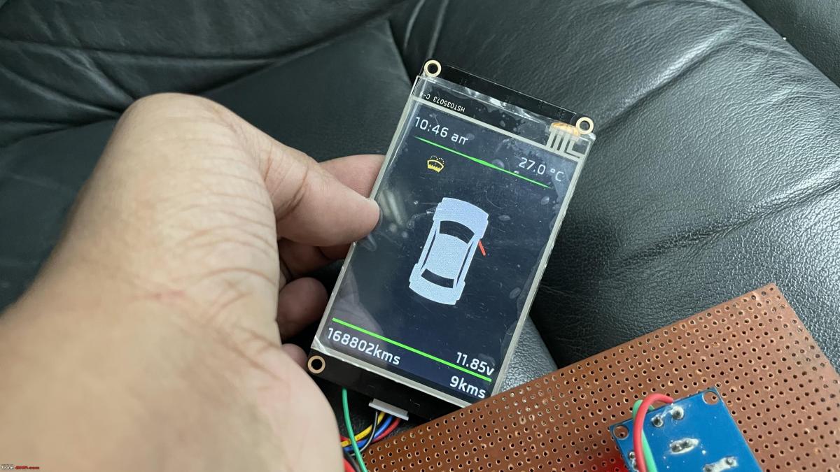
- Some UI elements needs refinement, on the above screenshot, the "m" of "am" is clipped, This is because the width of that text box is slightly shorter, there are a few such issues across pages.
- Currently trip data doesn't show decimal values - This is an issue, original MFD shows decimal values, however mine doesn't! This is because I'm calcuating the trip data by saving the odo reading to memory at the time of reset & taking the difference of current reading and the reading when trip was reset. The odo reading available in the convenience CAN Bus doesn't have decimal values. This is an important feature that needs to be fixed.
- Settings menu is missing - On the orignal MFD, there is a settings menu for configuring the coming home & leaving home time, units & winter tyres - Need to implement this
- Implement range/distance to empty, average speed of trip
- Implement way to reset trip data on the fly
- Implement bulb blown messages - If there is a blown bulb, the original MFD will show throw an error with details of blown bulb. This data is available in the bus, need to decode & code that in.
- Implement boost gauge, intake air temp, EGT & coolant temperature - This will need KLine reading, for future as KLine interfacing ICs are experiencing shortage as part of the global auto chip shortage.
I'm currently running the setup along side the original MFD in an attempt to identify & fix any issues, will be fixing the screen inside the cluster shortly, will keep the thread updated.
As for the sources, I'm planning on releasing the Arduino code, schematics & the Nextion HMI file as an open source project via Github. I'm currently in the process of polishing the edges to make it presentable to a wider audience.
- Tags:
- Indian
- Skoda
- Member Content
- DIY
- Laura
Find Car News
Just News


About Us