DIY - Fixing a Messy Wiring For XenonPlanet Micros
XenonPlanet has an authorized installer in Bangalore at Evo, from whom a few of us have installed their Micro Bi-Xenon fog lamps. We have had a few issues such as bad bulbs and poor bulb seating leading to streaks and incorrect output. To see more of this, please see Dr. Naren's ownership thread and how we subsequently fixed them.
Link
One issue that has always remained worry some for us and more importantly, dangerous, is how the wiring was done by Evo.
Not only is it below safe wiring standards, it's also dangerous in some cases. The worst hit being in Dr. Naren's car. As of this writing, we are trying to rectify it.
My case wasn't great either. For the location where the fog lamps are placed, it is essential and extremely important to ensure a water tight connection because that area receives the heaviest and strongest water splashes. Evo did a poor job (in our opinion) here because they did a strip and join wire connection secured with electrical tapes. We believe, these have the following issues.
- High possibility of corrosion in the long run due to electrical tapes being used to seal the joint. The connection is as good as how long the tapes last. In Dr. Naren's case, they have already come off.
- Not an industry standard way of creating reliable, good wire connections.
- Tall claims of high quality install is far from true with such an approach.
- Wipes out electrical warranty completely. Maruti does mark after market additions in their services, but poor wiring is something that they clearly call out and make note of in their database.
- Wires were let as it is in the base of the bumper and not secured properly. Given that this area gets water splashes and lot of vibrations, securing the wires is important.
- The solenoid wires are thin and it is recommended to have additional protection for long life. XP gives two year warranty on Micros
After making multiple visits to Evo by BHP-ians Dr. Naren, myself and lovetorque and not satisfied with the overall quality of install, we decided to take up the matter with XP and also try and fix the issues by ourselves where possible. I decided to improve the wiring myself yesterday and this DIY post is a documentation of my efforts.
IMPORTANT NOTE: I have very little experience in car electrical wiring. With help from many BHPians I attempted to improve this wiring. I, in no way, claim to have done a perfect job, but we do know from our discussions that this effort is far better than what experienced installers do and call as a high quality install. If anyone notices issues with this install, feel free to post it up so that we can improve it further
The changes done are simple. Use proper water proof connectors to secure the wiring joint. Secure the fragile wires using tubes and secure the wiring harness as appropriate.
Connectors used - Thanks to BHPian audioholic for giving it for free. Thanks audioholic! - It was great meeting you and discussing lighting. Your knowledge just blew me away. I wish we had more time to talk, but there's always a next time, isn't it?
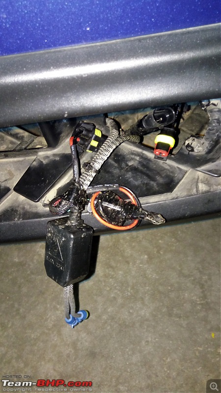
 Now, for the dirty laundry
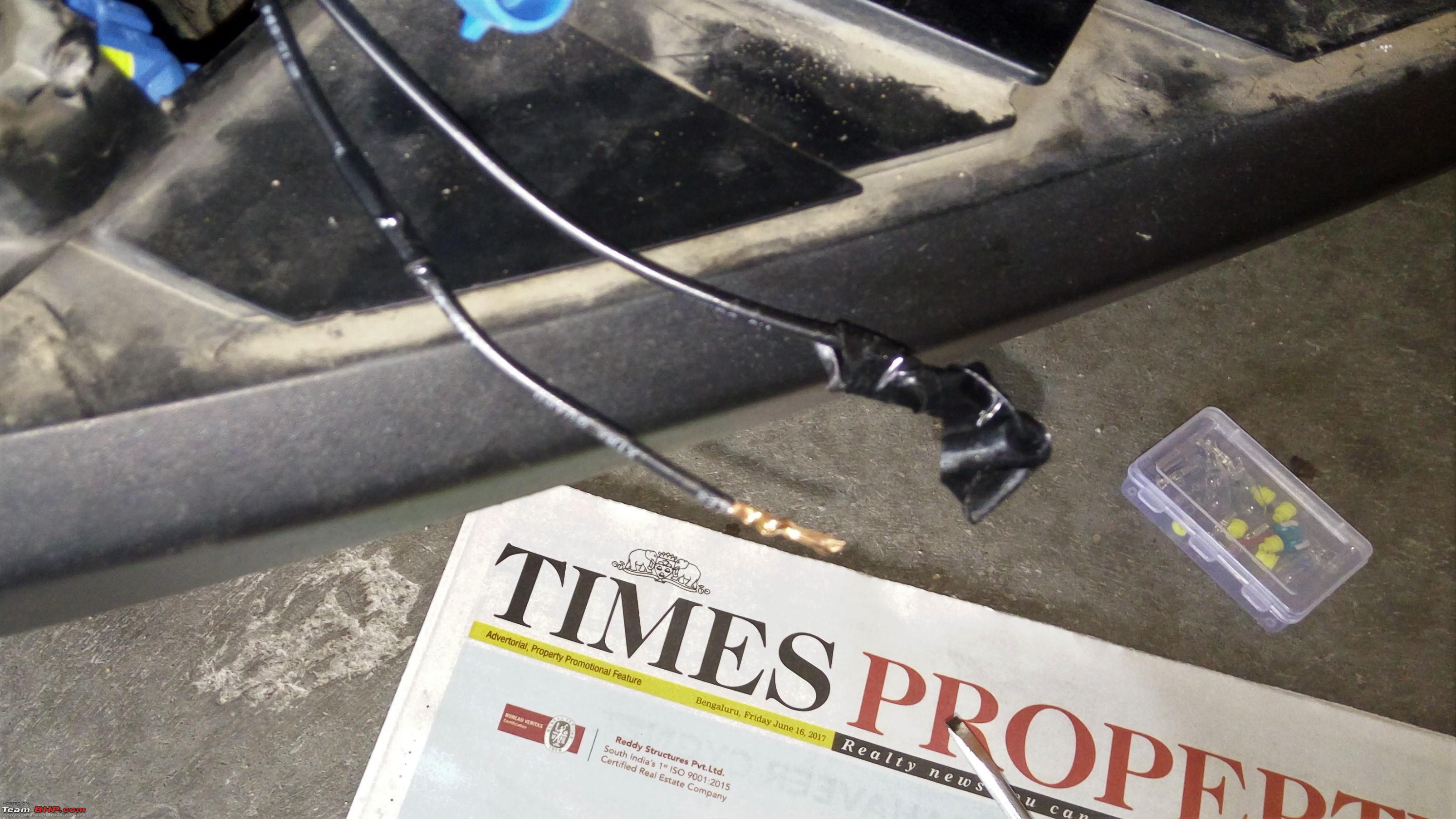
In the next picture notice the wiring harness used to tap power from the stock fog lamp connector. It's the worst I have seen! The reason for this approach from Evo was because the bulbs that came with the projectors were older bulbs (with a plastic base and open pins for connection to stock as opposed to a proper male connector; see previous update post on this, left most bulb). The newer ones have this corrected and it's plug and play. During the install, the additional harness used also had two separate pins but had better connection. Those pins were pushed into the stock connector. It was pushed
So tight that it had almost broken the connector inside (although very tight connection). It took me a full five minutes to pull them out during this DIY, not to mention all the glue that had stuck to the wiring.

Additional wiring used - You can see the gauge of wires used. In my case, this is good, but in Dr. Naren and BHPIan lovetorque's case, they used speaker wires!!

I wanted to call out Distinguished BHPian a4anurag's words here during a discussion on these issues -
Do it right, the right way, else don't do it. Don't think that needs any explanation.
Preparing the connectors and adding the new wiring
Tools

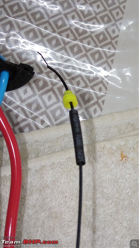
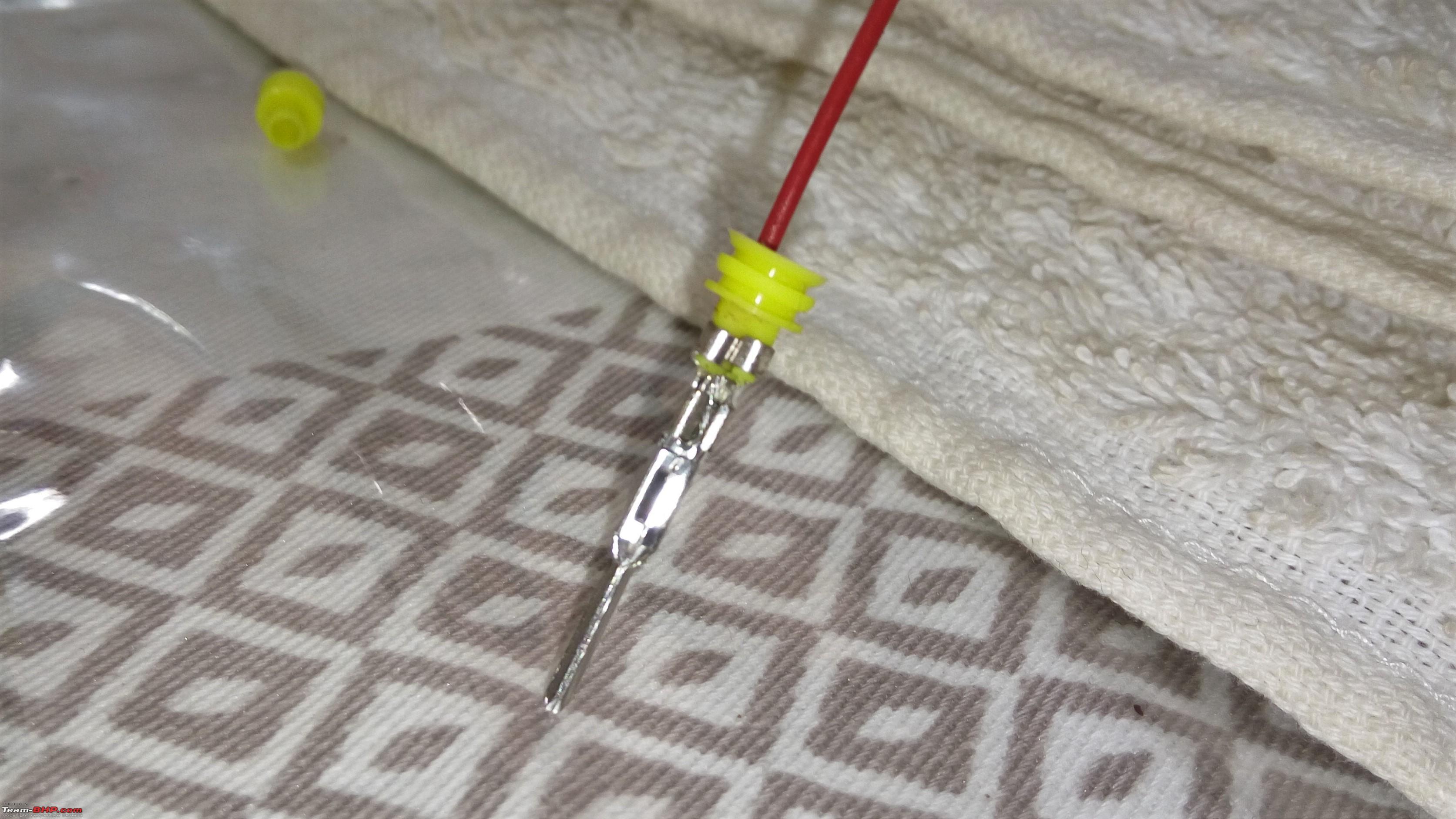
Slide the water proof seal and, if required, a heat shrink tube into the wire
Crimp the wires using a good wire crimper.


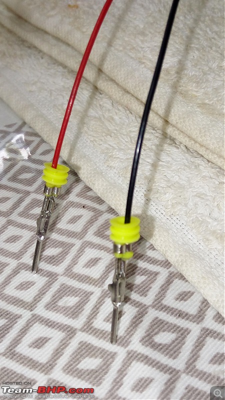
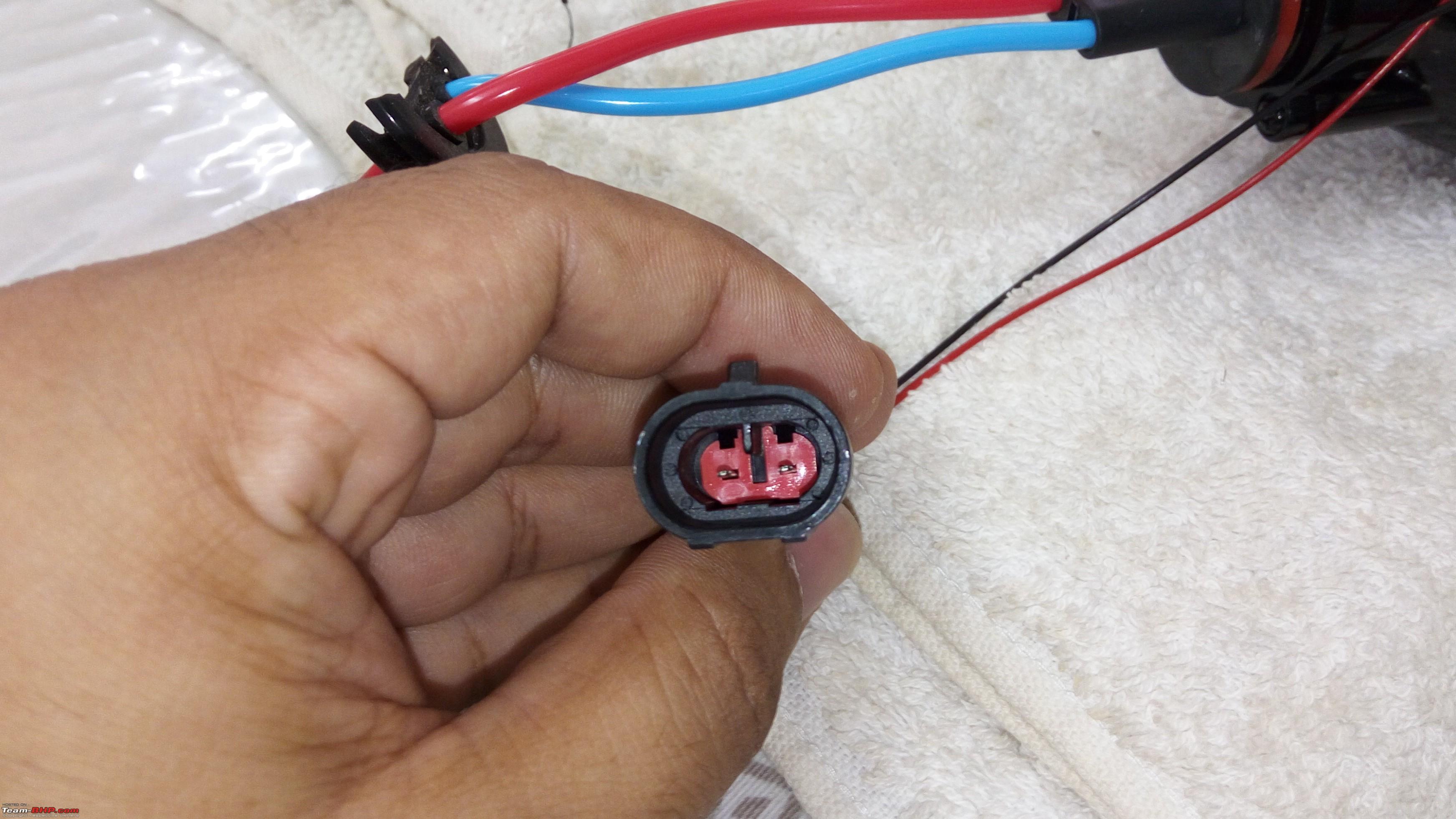
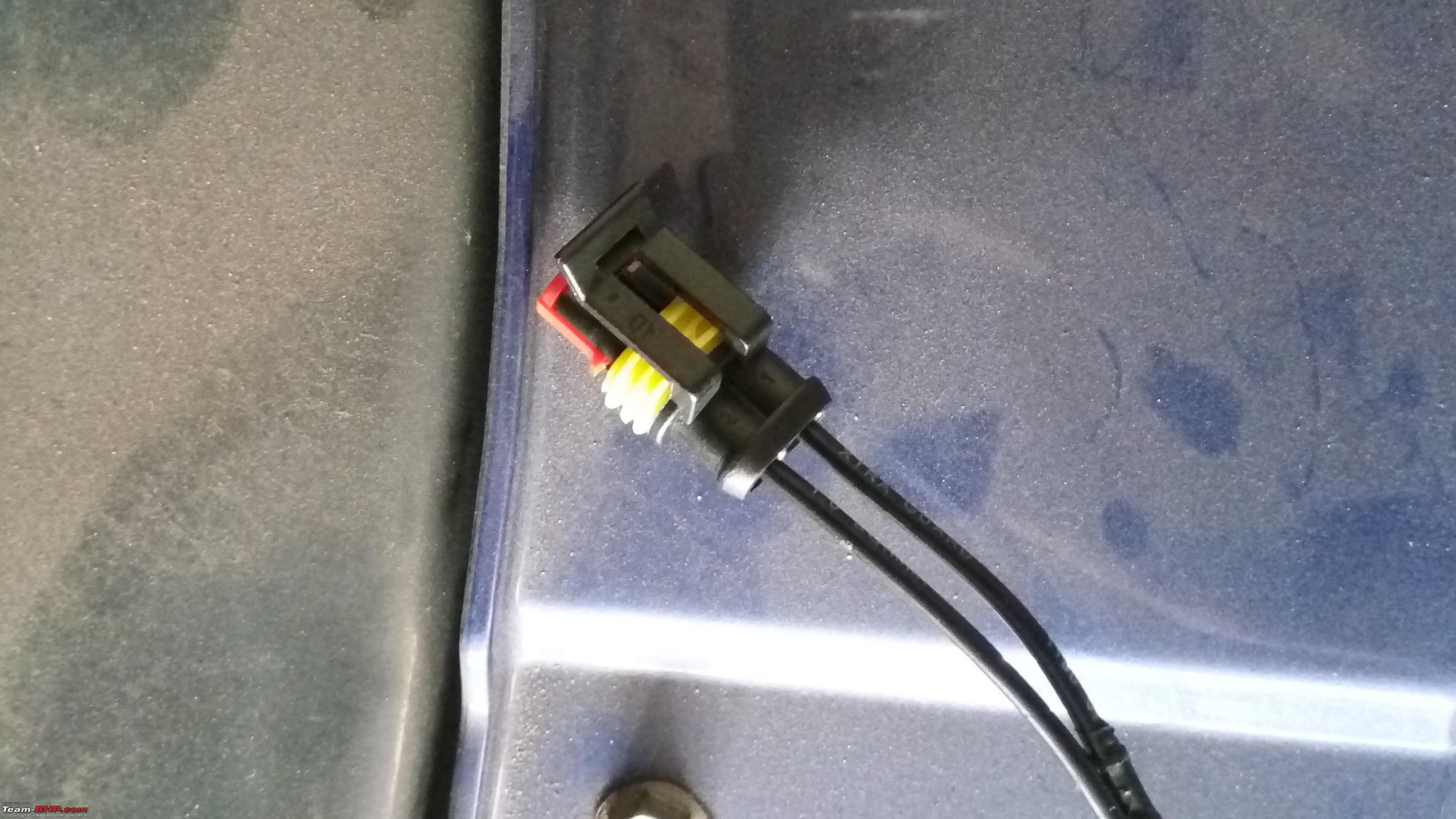
Insert the pins into the female connector with the locking pins facing down. Also to note that the connector has a number marking for wire pairing. In my case 1 is for ground and 2 is for positive.
Ensure they match on both male and female connectors, or else you will short circuit the line Trivia: After I finished this project, I found out that the connectors should have been interchanged, i.e the male connector should be attached to the projector wires and female connector to the wire for the high beam signal. That seems to be the norm, but it doesn't matter in this case.


Repeat the process with the male connector
H]
Connect it up

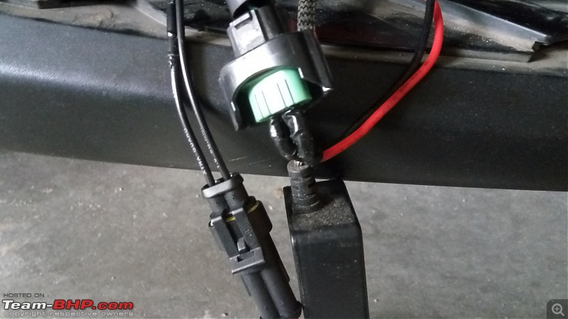
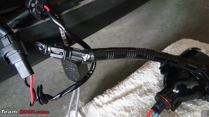
Complete connection - In this picture, to the left and middle, you can see the connections made using the supplied wiring harness by XenonPlanet. It's literally plug and play. To the extreme right is the new connector we applied.

The blue connectors are the output from ballasts to the bulb and to the left is the connection I created for the high beam's solenoid operation.
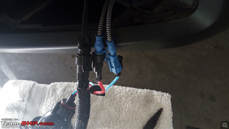
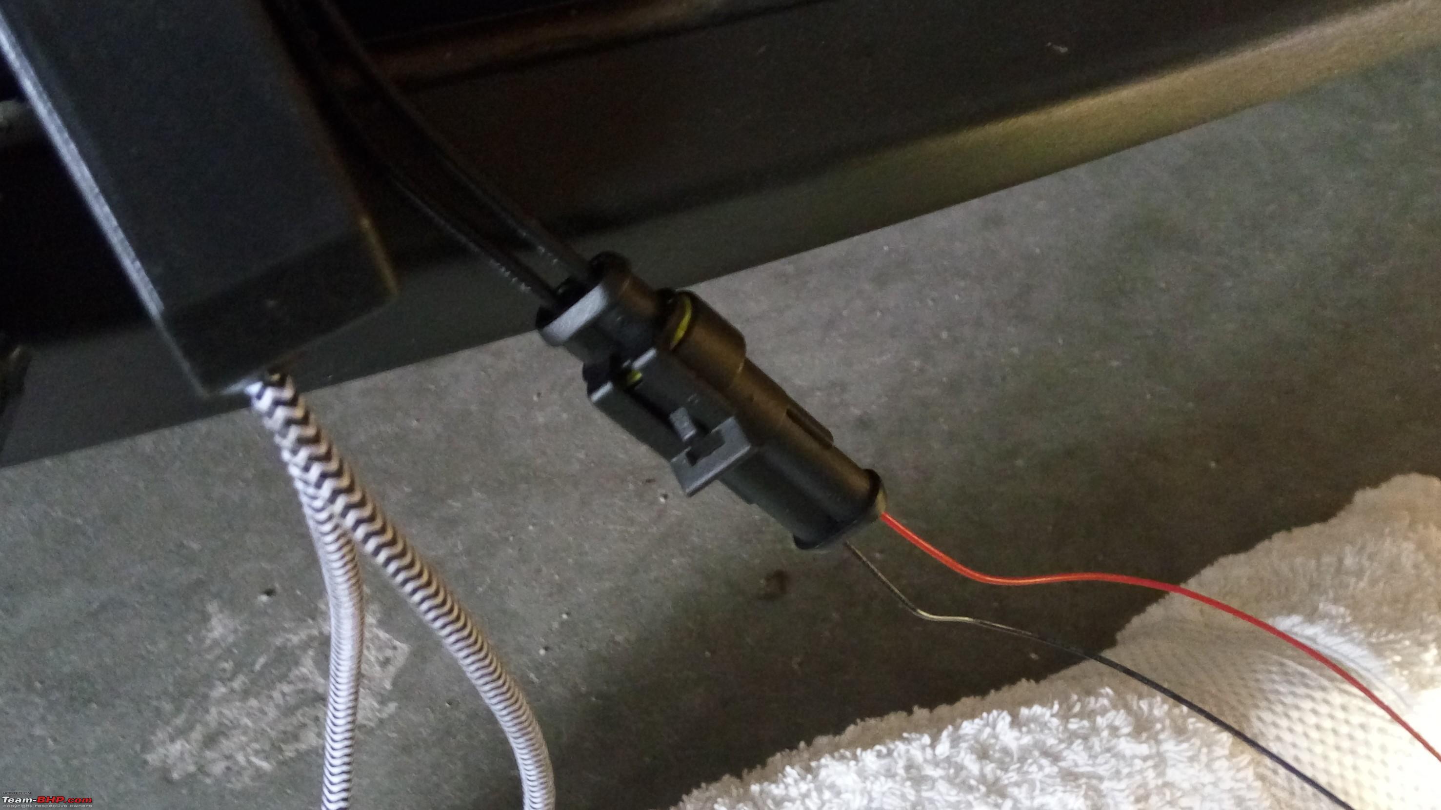
All connections complete.
- Extreme left - Power from stock connector using supplied wiring harness going into middle connector which is to ballast
- To the extreme right is the connection from this DIY
- To the bottom is are the blue connectors which is output from ballast to the bulb. Notice the black box in the middle, which is the igniter, I believe
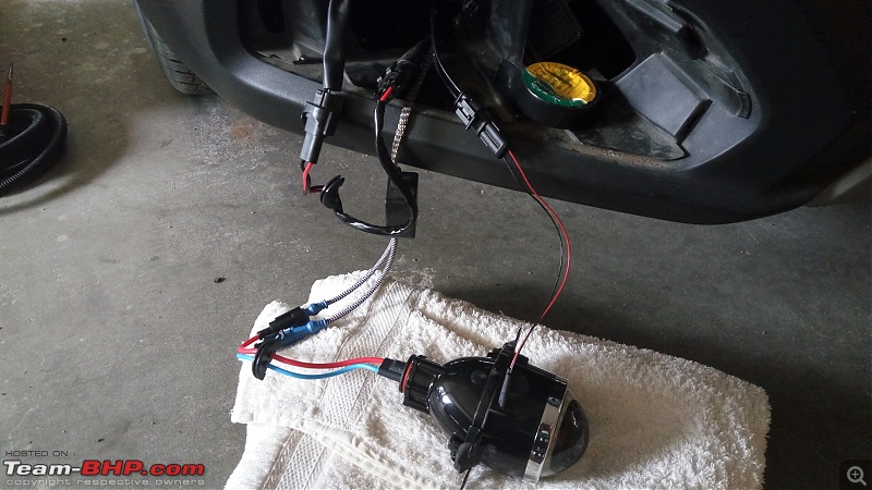
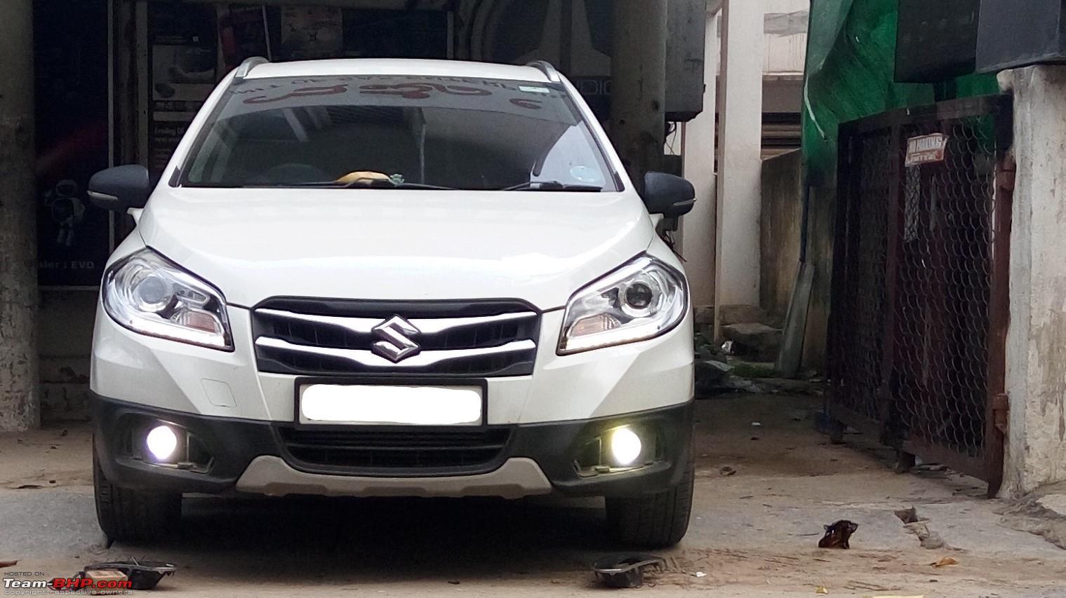
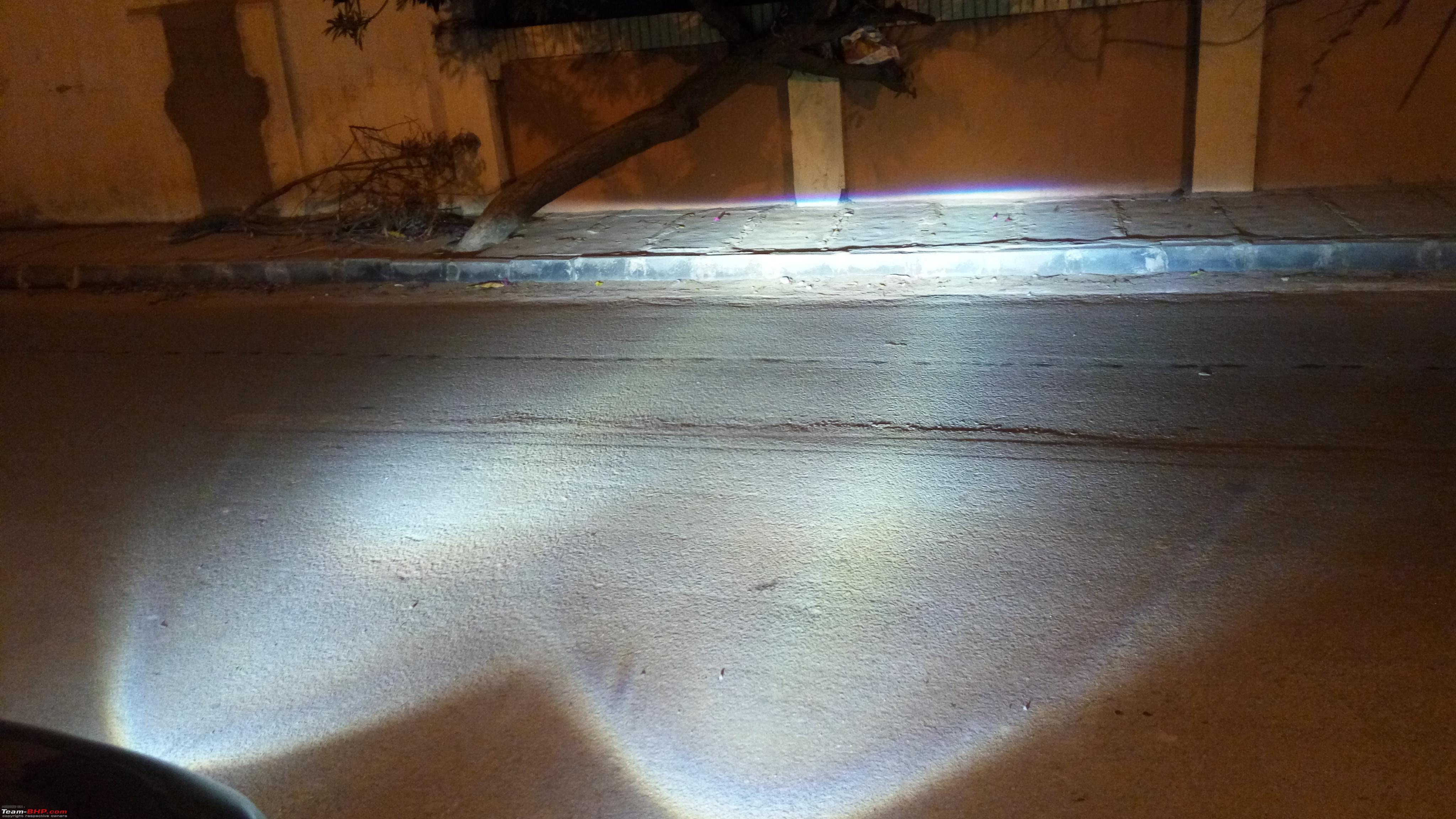
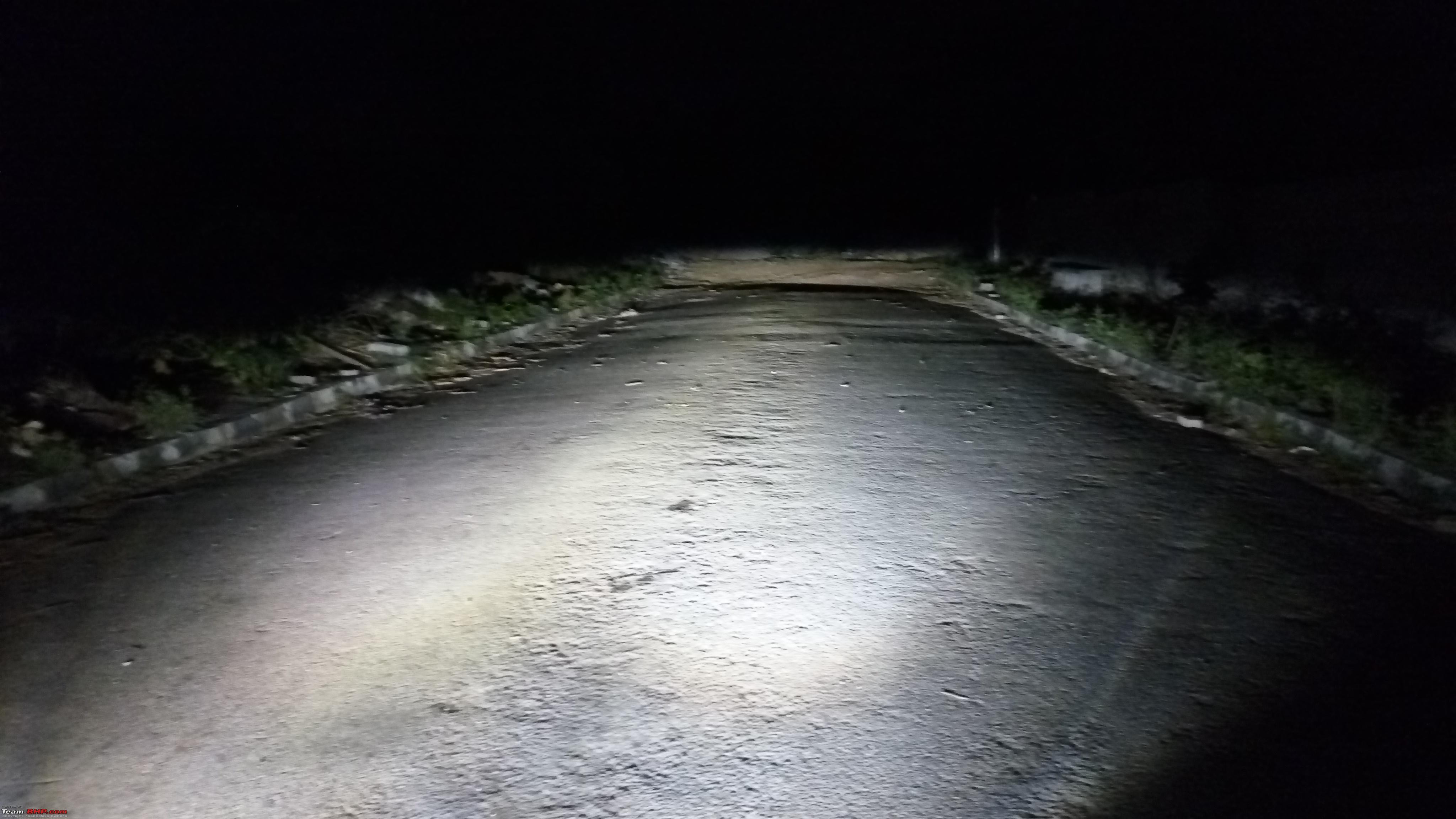
Fired Up - Let there be better light!

As an additional precaution for the wiring, I applied water proof tubing over the solenoid wiring to make it more secure. Comments, anyone?
 Next DIY: Fixing the high beam tap
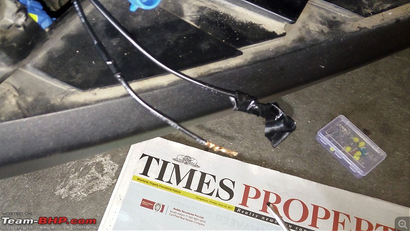
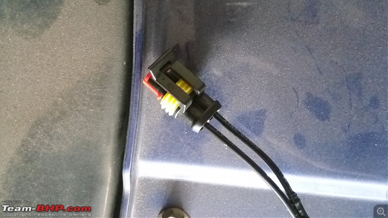
The high beam signal has been tapped using a splice connector, which we all know are not water proof or even recommended. Considering the engine bay gets washed, it is important to secure this tap. Possible solutions include using a heat shrink tubing or using a silicone sealant such as AnaBond 666 to secure the sides of the splice connector (Don't push the sealant in where the contact points are, just where the wires enter the connector). XenonPlanet is working to get heat shrink tubing over the connector, but I have no idea how they can do it without removing the wiring first. Removing it will be a very bad idea. On the other hand, Anabond is an industrial sealant that can work in high temperature conditions, resists moisture and also used in electrical wiring. I am going to wait and watch how XP goes about this.
Another S-Cross owner Rakesh's (From Pune) case is the worst where the high beam signal has been tapped from the fuse box in engine compartment. It's a fragile connection. The S-Cross has a separate fuse for low and high beam. The installer removed the high beam fuse, plugged in the wire and inserted the fuse back in. Anyone with common sense will know how long this connection may last and it will
NEVER make the fuse box water tight with the wire coming out. Really bad!
S-Cross head lamp fuses in engine compartment 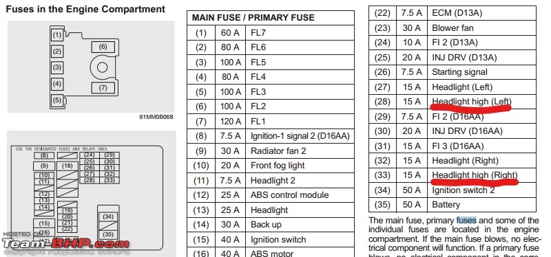 Setbacks faced during the install
- After wiring up the complete setup, the left fog lamp failed to power on. A little bit of troubleshooting proved that the wiring harness supplied by XenonPlanet to connect the stock fog lamp connector to the ballast was not functioning. Changing it resolved the problem.
- Frequent removal and fixing the fog lamps have caused them to have vibrations when going over potholes or mild patches that span across the road, much like the stock headlamp complaint that many have raised. It's due to a couple of screws not sitting tight. This still needs some solution
- When inserting the wire into male connector, I over pushed it which caused it to pop put over the connection side and wouldn't lock. A quick google search provided the solution on how to remove the wires from the connector. Essentially, there is a pin on the top that secures it. Using a small flat blade screw driver, lift it up and the wire comes out easily!
Credits- Dr. Naren - For continuous, unbiased feedback (good & bad). It helps improve a lot of things in our car
- Distinguished BHPIan: a4anurag - for all the helpful advice and smart solutions
- audioholic - For providing me with free connectors and free advice during the DIY.
- Rajat from XenonPlanet - For being a listening post to our issues, acknowledging problems, help trying to sort out issues and being active with communications
IMPORTANT NOTE & DISCLAIMER
I, in no way, in this post intend to disgrace or defame any institution or individuals. I am merely sharing my observations based on my understanding in how secure wiring should be applied to ensure continued electrical safety and warranty in the best possible manner. This DIY is a direct result of concerns & problems some of us have faced, in talking to subject matter experts on wiring car electricals. It is my need to ensure safety and trouble free ownership of my beautiful S-Cross. I like to keep my cars as perfect as possible - I should be able to drive it at any given point in time without having fear or have reliability concerns due to these aftermarket solutions on a journey (unless of course due to some unforseen circumstances).
Hopefully this information is useful to the community here. Thanks for reading


 11th June 2017, 22:04

 (5)
Thanks
(5)
Thanks


 . I couldn't believe that I paid 2500 Rs for the dirty unsafe installation job done at EVO. It's high time Xenon Planet find a better installer to offer at least safe wiring for Bangalore customers.

