Quote:
Originally Posted by Mpower  Sweet, I'm not able to see the plenum or the intake pipe in your picture.
IIRC the CBR954 uses an airbox and not a plenum. Whats the dia of the CBR's TBs and how does it compare to the stock ones. |
There is no plenum, nor am I planning to put one. Velocity stacks and 4 air filters will complete the setup. The TBs are 42mm at the butterfly. They taper from 45mm to 41mm ID.
Quote:
Originally Posted by ported_head DIY projects are always super! Congrats on taking up something like this. |
Thank you!
Quote:
|
The biggest problem as I see it is the location of the fuel injectors. The angle and nature of spray is important to the quality of combustion. In the stock motorcycle ITBs, the injectors spray at the back of the valve. Also, often individual ports are not circular, but oval. So type of injector spray would be important, I think.
|
Unlike the usual 4 hole injectors, these are 12 hole injectors. Therefore, the drops of fuel are smaller than what you have with the usual injectors. This means that the fuel atomises better even at lower air velocities. The ports are circular btw, and the 42mm ports can make a maximum of around 50-55 bhp per cylinder.
Quote:
|
Does the 954 use dual-stage injection? In your current setup, it would be difficult to achieve accurate tuning or reasonably steady state conditions. The fuel mixtures would vary considerably from one cycle to another, since the injectors look like they are spraying directly at the manifold walls. It would only get worse at higher rpms.
|
The 954 has single-stage injection. I cannot say this from experience, but I do not believe the injector locations to be a problem. People have done it successfully and made daily-driven racecars making around 180-220whp (cams included) with exactly the same setup.
Quote:
|
Why don't you change the location of the fuel rail to bring it closer to the ports?
|
This setup is the first step and by no means the final version. The next version is going to incorporate a few more fun things

Quote:
|
Though when I tried to make my own manifold, I had maximum trouble trying to get the injector angle accurate. You will probably have to drill some eccentric holes and make tapered bungs.
|
Already planned on how do that in the next version, though a little differently.
Quote:
|
But you seem to have access to some good labour and machinery so shouldn't be too tough.
|
Machinery, perhaps. Just the standard CNC machine, a computer, a pair of hands and a few tools. Labour? Let's just say there have been times when I've felt like kidnapping the labourers' kids to make them work. The project was to be finished on the 20th of last month, as a few people know already. The festivities and laziness pushed it much farther. And I'm only talking about stuff like welding, drilling holes or procuring raw material which either required a machine which I didn't have or some special skill. Everything that didn't need a machine was done by me; removing the manifold, measuring, cutting, putting together certain equipment, procuring equipment from customs, drawing the stuff on the computer, etc.
Quote:
|
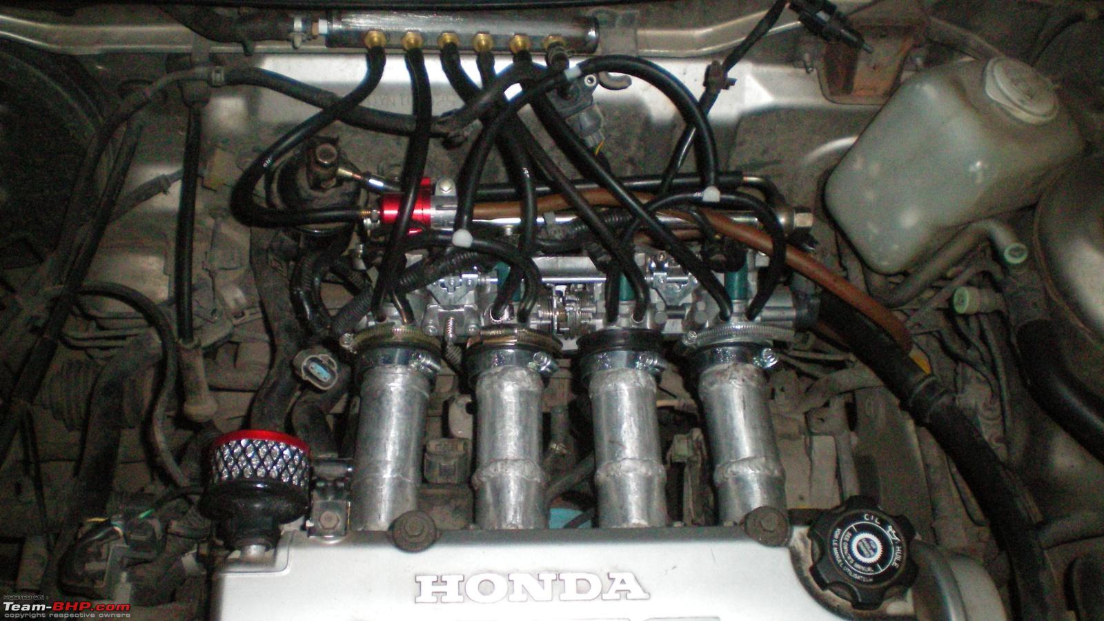
Also, why are the manifolds welded midway?
|
The manifold is in 3 parts. The flange is a 1:1 copy of the stock D16y7 intake manifold flange that the OHC has. The second/middle step are 4 "adapter" pieces which convert the D-shaped intake ports into circular ports which can then be mated to the ITBs. However, the distance between the intake ports on the flange and each throttle body is not the same. Hence the need to taper the pipes at a specific degree to meet the ITBs at a perfect angle.
Quote:
Originally Posted by Mpower Good observation Ported. I missed it completely. Although I think the low rpms will be the issue. if its a sequential system you might even end up running lean. |
The ECU is a Honda OEM, so it's batch injection.
Quote:
|
Easier option if the take the stock mani and slice it just upstream of the injector bungs and build your runners from there. That way you retain the stock flange and injector location.
|
That was another option. However, sacrificing the stock manifold was not possible, neither was buying another one.
Quote:
Originally Posted by nitrous What air filters are you going to use? |
Pipercross bike filters, 4 of them.
Quote:
Originally Posted by ported_head Crome provides for sequential injection, I think. Because Nitroxx's city was also running Crome. |
Crome doesn't. Neither does any other offering for OBD1 Honda ECUs as far as I know. Doesn't it depend on the ECU though?
Quote:
|
My concern at higher rpms is that volumetric efficiency maybe affected quite a bit.
|
Like I said above, the 42mm ITBs can make upto 55bhp per cylinder. That's pretty much the limit on an N/A D15 engine anyways.
Quote:
|
I know that the 600RR ITBs have a 2-3 degree taper over their length. And the port geometries are pretty complex.
|
So do these. They taper from 45mm to 41mm.
Quote:
|
Do you think that because the motorcycles run a fixed length intake, they compensate using injectors with different spray patterns?
|
Barring a few OBD1 Hondas with variable length intake, how is this different from motorcycles?
Quote:
|
In the 600RR, the distance from the back of the valve to the point of attachment of ITBs was about 2.5 inches (sloppy measuring though). The injectors are aimed to spray directly at the back of the valve.
|
The distance between the valve head to various things like injectors, butterfly, velocity stacks determine the optimum powerband, which I guess you already know. However, mounting them ITBs directly to the engine, or that close to the engine would mean that the engine would have to run at insane RPMs to make all that power. And we're talking about a D15 engine which would pretty much run out of breath at around 8.5k, valvetrain upgrades included.
Apologies if I've missed any questions.


 30th October 2009, 10:46