| | #31 |
| BHPian Join Date: Jul 2015 Location: Bangalore-Kochi
Posts: 625
Thanked: 3,233 Times
| |
| |
| |
| | #32 |
| Senior - BHPian Join Date: May 2011 Location: Meerut, India
Posts: 3,570
Thanked: 9,341 Times
Infractions: 0/1 (5) | |
| |  (6)
Thanks (6)
Thanks
|
| | #33 |
| Senior - BHPian Join Date: Nov 2009 Location: Bombay
Posts: 1,898
Thanked: 4,537 Times
| |
| |  (1)
Thanks (1)
Thanks
|
| | #34 |
| Senior - BHPian Join Date: May 2011 Location: Meerut, India
Posts: 3,570
Thanked: 9,341 Times
Infractions: 0/1 (5) | |
| |  (1)
Thanks (1)
Thanks
|
| | #35 |
| Senior - BHPian | |
| |
| | #36 |
| Senior - BHPian Join Date: May 2011 Location: Meerut, India
Posts: 3,570
Thanked: 9,341 Times
Infractions: 0/1 (5) | |
| |  (1)
Thanks (1)
Thanks
|
| | #37 |
| Newbie Join Date: Apr 2016 Location: Hyderabad
Posts: 24
Thanked: 21 Times
| |
| |  (1)
Thanks (1)
Thanks
|
| | #38 |
| Senior - BHPian Join Date: May 2011 Location: Meerut, India
Posts: 3,570
Thanked: 9,341 Times
Infractions: 0/1 (5) | |
| |  (1)
Thanks (1)
Thanks
|
| | #39 |
| Senior - BHPian Join Date: May 2011 Location: Meerut, India
Posts: 3,570
Thanked: 9,341 Times
Infractions: 0/1 (5) | |
| |  (15)
Thanks (15)
Thanks
|
| | #40 |
| BANNED Join Date: Aug 2008 Location: coorg/bangalore
Posts: 459
Thanked: 606 Times
Infractions: 0/1 (10) | |
| |
| | #41 |
| Senior - BHPian Join Date: May 2011 Location: Meerut, India
Posts: 3,570
Thanked: 9,341 Times
Infractions: 0/1 (5) | |
| |  (1)
Thanks (1)
Thanks
|
| |
| | #42 |
| Senior - BHPian Join Date: May 2011 Location: Meerut, India
Posts: 3,570
Thanked: 9,341 Times
Infractions: 0/1 (5) | |
| |  (5)
Thanks (5)
Thanks
|
| | #43 |
| BHPian Join Date: Feb 2015 Location: Mumbai
Posts: 29
Thanked: 33 Times
| |
| |
| | #44 |
| Senior - BHPian Join Date: May 2011 Location: Meerut, India
Posts: 3,570
Thanked: 9,341 Times
Infractions: 0/1 (5) | |
| |  (1)
Thanks (1)
Thanks
|
| | #45 |
| Senior - BHPian Join Date: Jul 2005 Location: Dehradun
Posts: 2,299
Thanked: 3,371 Times
| |
| |  (1)
Thanks (1)
Thanks
|
 |
Most Viewed


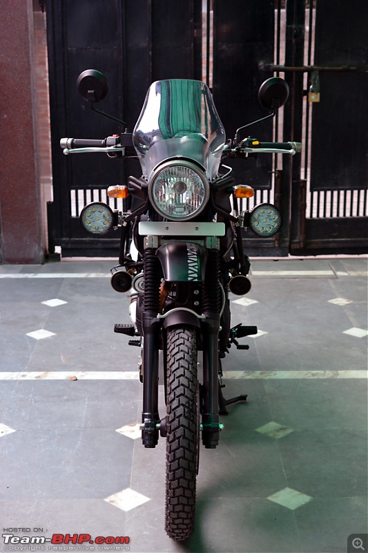
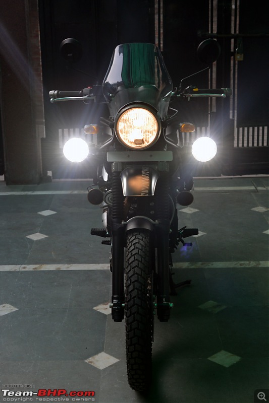
 . However, in an event the bike falls, the 1st thing to go will be those lamps sirjee. Why don`t you try placing the lamps close or in line to the main HL. This should give you much better lighting on the road and a bit of safety on damage of the aux lamps. Just my 2 cents.