Quote:
Originally Posted by myavu  But this time let us all buy it from Kits'n'Spares (easy troubleshooting) and as a brand Omron looks durable and last car's life. Will order 2 buttons.
My only concern is how to open the plastic cover of console safely (without breaking any clips or body) and solder the button without detaching the console PCB (soldering by just sitting on the driver's seat  )
Kindly demonstrate how to open the plastic cover of console without opening or unscrew any other parts related to dash or steering.
Cheers!
Vinu |
Omron is a good quality OEM product.
B3AL switch Potential applications include automotive instrument panel, medical equipment, and gaming equipment. So definitely it will be more reliable.
Regarding opening of plastic cover, don't worry much about the breakage of clips - it is just an additional locking, there are 2 screws for mounting the cover. Posting some pictures of the cover for better understanding:
There are 3 clips on the bottom cover - 2 on RH side and 1 on LH side.
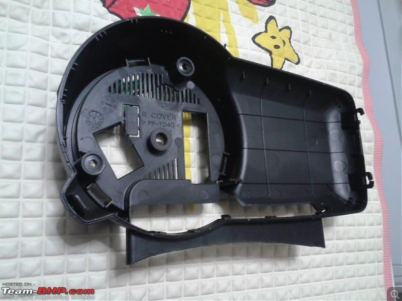
There are 6 clips on the top cover - This is easy to remove since the clips are visible once the rear cover is removed. Also note the extra long leg of the dummy switch button.
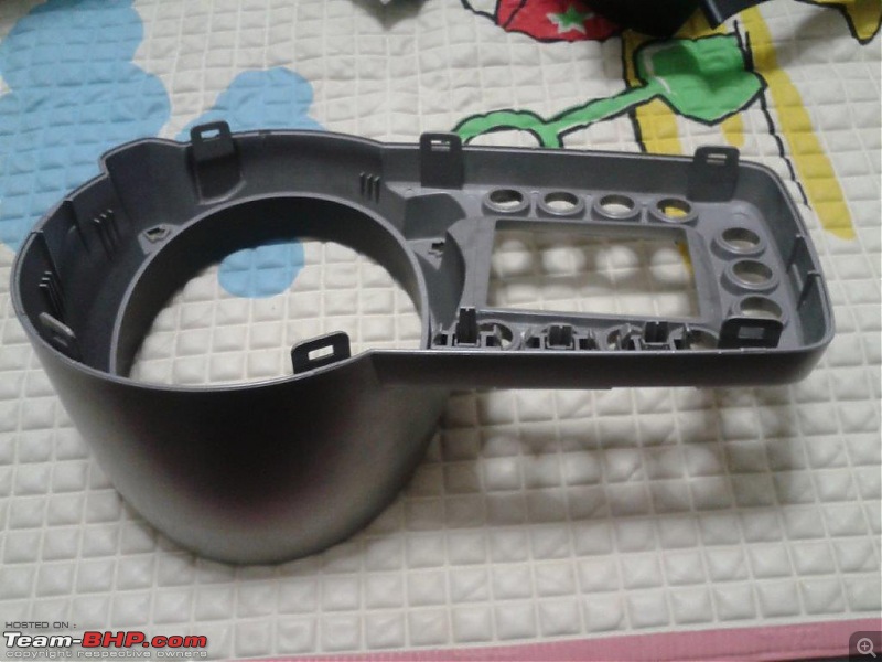
Dummy switch button long leg - we get a reference length by comparing with other buttons.
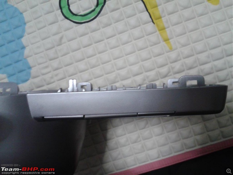
Note the 2 Philips screw holes - so don't worry about breaking clips

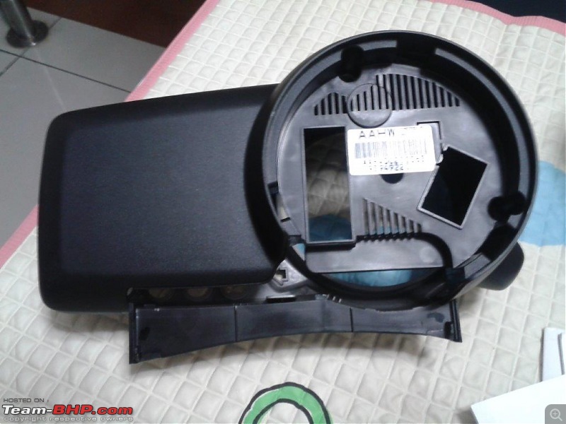 SOP / The steps for removal:
1. Remove one screw near the bonnet open lever and pull the cover outwards with reasonably good force. Tool: Philips head screw driver.
2. Remove steering column bottom cover - 3 screws to be removed: 1 near the steering tilt lever and 2 from top(you will find it if seen from the driver seat, rotate the steering). Tool: Philips head screw driver.
3. Flip open the plastic round nut cover from top of the instrument cluster. Try with finger nail or else use a flat head screw driver. 10mmA/F nut will be visible from top.
4. Use a 10mm box spanner and remove the nut completely.
5. The second nut is from bottom - you need to disconnect the wiring harness connector to the wiper stack/combination switch. can be done by hand, pull by holding the connector - not wires.
6. Now second nut from bottom will be visible. Use 10mm box spanner and remove the nut completely.
7. Take-out the instrument cluster by releasing the mounting bracket from the 2 mounting bolts.
8. There is a plastic cap behind the round portion of the console - this is just press fitted. Use a sharp knife / flat head screw driver to remove cover.
9. Now the wiring harness connectors will be visible - One green connector & another black connector. There will be a latch lock for the connector. To release the latch, use a flat screw driver and press the locking slot and pull the latch outwards slowly. The connectors are self release type - it will come out as you pull the latch outwards. Similarly, remove the other connector also.
10. take out the instrument console to a comfortable place and remove 2 philips screws from rear side. Using a flat head screw driver or any other flat pointed tool, split open the 2 plastic covers, first the rear cover(black) followed by front cover(silver for LT/black for base variants)
11. Now the tact switch can be soldered to the PCB.
12. Cut the extra long leg of the dummy button. Check for free movement of the dummy switch. If tight, then clear any fouling projections using a knife.
13. Close the covers and assemble the items in the reverse sequence.
14. Over!

Hope the above steps will be helpful to you. You may contact me in case of any doubts during the DIY.
 (1)
Thanks
 (1)
Thanks
 (1)
Thanks
 (6)
Thanks
 (1)
Thanks
 (1)
Thanks
 (2)
Thanks


 .
.



 .
.


 When are you coming to Kochi next time. Me too will plan accordingly.